Table of Contents
Advertisement
EN
24V
SWING GATES
PORTAIL
24V
À BATTANT
V1
TEHA CONNECT
CONNECTED MOTOR
DRIVE KIT
With actuators – For two-panel swing gates
Ref. 114174
L
1.75 M PER
150 KG PER PANEL
1,75M
150KG
PANEL
PAR BATTANT
PAR BATTANT
KG
COMPATIBLE WITH ALL
COMPATIBLE TOUS
TYPES OF OPENWORK
TYPES DE PORTAILS
GATES
BACKUP BATTERY
COMPATIBLE WITH
OPTION
OPTION COMPATIBLE
OPTION
AVIDSEN HOME
BATTERIE DE SECOURS
SMARTPHONE
www.avidsen.com
TECHNICAL
SUPPORT
3
WARRANTY
Advertisement
Table of Contents

Related Manuals for Avidsen TEHA CONNECT


Summary of Contents for Avidsen TEHA CONNECT
-
Page 1: Menu
TECHNICAL SUPPORT WARRANTY TEHA CONNECT CONNECTED MOTOR DRIVE KIT With actuators – For two-panel swing gates Ref. 114174 SWING GATES 1.75 M PER 150 KG PER PANEL COMPATIBLE WITH ALL BACKUP BATTERY COMPATIBLE WITH PORTAIL 1,75M 150KG COMPATIBLE TOUS OPTION... -
Page 2: Table Of Contents
CONNECTED MOTOR DRIVE KIT WITH ACTUATORS CONTENTS A - SAFETY INSTRUCTIONS D - BEGINNING OPERATION 1 - OPERATING PRECAUTIONS 1 - SETTINGS INTERFACE 2 - INSTALLATION PRECAUTIONS 2 - QUICK SETTINGS 3 - MAINTENANCE AND CLEANING 2.1 - Self-learning 2.2 - Adding remote controls 4 - RECYCLING 2.2.1 - Programming with the card B - PRODUCT DESCRIPTION... - Page 3 E - USE F - MAINTENANCE AND UPKEEP 1 - WARNINGS 2 - OPENING/CLOSING 1 - MAINTENANCE WORK 2 - OPERATING INDICATORS 2.1 - Type of command 2.2 - Operating modes 2.1 - Event log and error codes 2.2 - Manual control 2.2.1 - “Semi-automatic closing”...
-
Page 4: A - Safety Instructions
• Do not manually activate the gate when the indicated in these instructions. motor drive is not disengaged from the gate. Avidsen cannot be held liable for any use that does... -
Page 5: Maintenance And Cleaning
CONNECTED MOTOR DRIVE KIT WITH ACTUATORS A - SAFETY INSTRUCTIONS 3 - MAINTENANCE AND CLEANING 4 - RECYCLING • Read all the instructions given in this manual Disposing of used batteries in household before carrying out maintenance on the waste is strictly forbidden. Batteries/ motorised gate. -
Page 6: B - Product Description
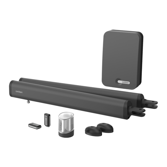
CONNECTED MOTOR DRIVE KIT WITH ACTUATORS B - PRODUCT DESCRIPTION 1 - CONTENTS OF THE KIT Actuator Remote control Switchgear Photocells Flashing light Gate mounting bracket Post mounting bracket 2 - EQUIPMENT REQUIRED (NOT INCLUDED) The tools and screws required for the installation must be in good condition and compliant with applicable safety standards. -
Page 7: C - Installation
CONNECTED MOTOR DRIVE KIT WITH ACTUATORS C - INSTALLATION HAZARD ANALYSIS These maximum dimensions and weights are for an openwork-type gate and for use in an area that is not very windy. For use in an area with REGULATION significant wind speed, it is necessary to reduce the maximum values indicated above for the gate Installation of a motorised gate or a motor drive to be motorised. -
Page 8: Eliminating Hazards
CONNECTED MOTOR DRIVE KIT WITH ACTUATORS C - INSTALLATION SAFETY RULES The actual opening of a gate may create dangerous situations for people, goods and vehicles in the vicinity that by nature, cannot always be avoided by design. The possible hazards depend on the state of the gate, the manner in which it is used and the installation site. -
Page 9: Installing Actuators
CONNECTED MOTOR DRIVE KIT WITH ACTUATORS C - INSTALLATION Between the panels and the fixed parts close to each other Depending on the configuration of the site where the motorised gate is installed, there may be confinement areas between the panels in open position and the fixed parts close to them. To remove these areas, it is mandatory to leave a safe distance of 500mm between the fixed part and the moving parts of the motorised gate. hazard solution post post confinement area 500 mm minimum view from above PREVENTING OTHER HAZARDS The body of a switch with no lock must be located in direct view of the driven part but away from moving parts. -
Page 10: Maximum Opening Angle
CONNECTED MOTOR DRIVE KIT WITH ACTUATORS C - INSTALLATION 2.1 - MAXIMUM OPENING ANGLE The installation of the actuators depends on the desired opening angle which depends on distance D (the distance between the axis of the hinge and the inner side of the post). Normal case •... - Page 11 CONNECTED MOTOR DRIVE KIT WITH ACTUATORS C - INSTALLATION Switchgear Flashing light photocells actuators Mandatory central stop (not included) Mandatory side stops (not included) Inner side of the property Attaching the post mounting bracket Mount the actuators to a rigid and reinforced part of the gate (e.g. the frame or the crossbar). Mount them as low as possible for aesthetic and technical reasons.
- Page 12 CONNECTED MOTOR DRIVE KIT WITH ACTUATORS C - INSTALLATION • The height of the centre of the mounting bracket must be the same as the centre of the gate frame on which the actuator is mounted. post 31mm D (mm) B (mm) max angle (°) 120°...
- Page 13 CONNECTED MOTOR DRIVE KIT WITH ACTUATORS C - INSTALLATION Battery con- Rod movement direction 48mm nection 5 mm black carriage stop black free space Assemble the actuator rotation axis with the post mounting bracket Using a butterfly screw, assemble the gate mounting bracket with the actuator. STEP 1: Use the 9 V battery to move the “carriage” to the end of the actuator, then back 0.5 to 1 cm inwards STEP 2: Close the gate by pressing it securely against its central stop, then rotate the...
-
Page 14: Installing The Switchgear
CONNECTED MOTOR DRIVE KIT WITH ACTUATORS C - INSTALLATION STEP 4: Keep only the mount and fix it to the gate using the appropriate fasteners STEP 5: Use the butterfly screw to reattach the actuator on the mount 3 - INSTALLING THE SWITCHGEAR The switchgear must be mounted to the post where the 230Vac power comes from. -
Page 15: Installing The Flashing Light
CONNECTED MOTOR DRIVE KIT WITH ACTUATORS C - INSTALLATION 4 - INSTALLING THE FLASHING LIGHT The flashing light must be fastened at the top of the post on which the switchgear is attached and must be visible both inside and outside. Only use the light provided in the kit (24 V - 2 W). The flashing light may be fastened on the wall with or without support. • With a screwdriver, remove the transparent part of the flashing light by unscrewing the 2 screws that hold the upper part of the flashing light. • Continuing to use a screwdriver, remove the flashing light bracket by unscrewing the 2 screws inside the light. -
Page 16: Installing The Set Of Photocells
CONNECTED MOTOR DRIVE KIT WITH ACTUATORS C - INSTALLATION 5 - ATTACHING THE SET OF PHOTOCELLS 1 set of photocells • Install the reception photocell (RX indicated at the back) of the same side of the gate as the switchgear. The surface of the posts must be perfectly flat in order to properly align the infrared beam of the photocells. - Page 17 CONNECTED MOTOR DRIVE KIT WITH ACTUATORS C - INSTALLATION 20mm Outer side of the property 2 set of photocells For use when the gate is not visible. You must install a second set of photocells to prevent the gate from opening when an item (car, person, etc.) is behind the gate.
-
Page 18: Connections
CONNECTED MOTOR DRIVE KIT WITH ACTUATORS C - INSTALLATION 6 - CONNECTIONS • The cable run between must comply with applicable standards (NFC 15-100). • Either the cable is 80 cm deep with red warning mesh, or the cable is run through a sheath. 230V vers Safety instructions... -
Page 19: Actuators
CONNECTED MOTOR DRIVE KIT WITH ACTUATORS C - INSTALLATION Neutral Phase 6.2 - ACTUATORS For actuator wiring, use a 2x1.5 mm section cable and waterproof junction boxes. For each motor, the cable length must not exceed 8 m. • Opening inwards: black black * actuator installed on the panel that opens first... -
Page 20: Photocells
CONNECTED MOTOR DRIVE KIT WITH ACTUATORS BAT TRANS PROG C - INSTALLATION 6.4 - PHOTOCELLS BAT TRANS • Disconnect the removable terminal block, connect the photocell wires to the terminal block as shown in the diagram below and then reconnect the terminal block. 1 set of photocells Photocell RX1 Photocell TX1... -
Page 21: Control Parts (Optional)
CONNECTED MOTOR DRIVE KIT WITH ACTUATORS C - INSTALLATION BAT TRANS 6.5 - CONTROL PARTS (OPTIONAL) Note: These control parts must be normally open dry contacts. push button, intercom output. 6.6 - HOMEGATE CONNECTED MODULE BAT TRANS 230V AC Install the magnet enabling gate state feedback from the app. •... -
Page 22: Backup Battery (Optional Ref. 580293)
CONNECTED MOTOR DRIVE KIT WITH ACTUATORS C - INSTALLATION Electronic card Contactor Pre-wired Passive magnet magnet Grommet 6.7 - BACKUP BATTERY (OPTIONAL ref. 580293) The backup battery is useful in case the power is cut and it enables you to operate the motor drive for several days. -
Page 23: D - Beginning Operation
CONNECTED MOTOR DRIVE KIT WITH ACTUATORS D - BEGINNING OPERATION Warning: Operation must be begun and 2. QUICK SETTINGS adjustments made by a person qualified to 2.1. SELF-LEARNING work on this equipment because the active parts are accessible. Self-learning enables the card to learn how far the gate moves. -
Page 24: Adding Remote Controls
CONNECTED MOTOR DRIVE KIT WITH ACTUATORS D - BEGINNING OPERATION In phase 1, motor M1 was To diagnose any problems, here is the list of codes not detected (contact and their meaning: L3 L4 failure, electronic card : LED off problem?). -
Page 25: Programming With The Card
CONNECTED MOTOR DRIVE KIT WITH ACTUATORS D - BEGINNING OPERATION 2.2.1. PROGRAMMING WITH THE CARD 2.3. DELETING ALL REMOTE CONTROLS Programming a button for the COMPLETE To deprogram all the remote control buttons OPENING command: learnt, follow the procedure below •... - Page 26 CONNECTED MOTOR DRIVE KIT WITH ACTUATORS D - BEGINNING OPERATION After each new force, speed and acceleration adjustment, it is necessary to start a new self- learning procedure MENU 1 MENU 2 MENU 3 simple rules simple rules simple rules PROG 3s PROG 3s PROG 3s...
- Page 27 CONNECTED MOTOR DRIVE KIT WITH ACTUATORS D - BEGINNING OPERATION...
-
Page 28: Operating Mode (Automatic Closing Or Semi-Automatic Closing)
CONNECTED MOTOR DRIVE KIT WITH ACTUATORS D - BEGINNING OPERATION To choose the operating mode, follow this 3.1.1. OPERATING MODE (AUTOMATIC CLOSING OR SEMI-AUTOMATIC procedure: CLOSING) • Press on PROG 2 or 3 times and the green LED should be switched on (only the green LED) This automatic gate opening mechanism has 3 •... -
Page 29: Motor Force
CONNECTED MOTOR DRIVE KIT WITH ACTUATORS D - BEGINNING OPERATION This time is adjustable from 15 seconds to 90 3.1.4. MOTOR SPEED seconds by 15 second interval as defined in the table below (set to 30 seconds by default). You can adjust the speed by a value of 0 to 4. The default speed is 3. -
Page 30: Acceleration/Deceleration At End Of Travel
CONNECTED MOTOR DRIVE KIT WITH ACTUATORS D - BEGINNING OPERATION Acceleration – Photocell mode Type of gate Stop tolerance – – PROG PROG PROG PROG Acceleration settings Photocell mode Type of gate Adjustable tolerance + : increases acceleration + : increases tolerance –and + to set the value –and + to set the value –... -
Page 31: Type Of Gate
CONNECTED MOTOR DRIVE KIT WITH ACTUATORS D - BEGINNING OPERATION 3.2.3. TYPE OF GATE and L1 will turn on. • Press PROG for 3 seconds. L0 will flash twice. • Press “+” 3 times and L4 will switch on instead To operate the electronic card on a single-panel of L1. -
Page 32: Menu 0
CONNECTED MOTOR DRIVE KIT WITH ACTUATORS D - BEGINNING OPERATION 3.3. - MENU 3 2.5 s (par défaut) Closing time interval – Pre-flashing time 3.5 s PROG PROG 4.5 s Time settings Pre-flashing time Note: During opening, there is also a time + : increase time –and + to set the value –... -
Page 33: E - Use
2.1 - TYPE OF COMMAND situations. Avidsen cannot be held liable for any installation or There are two types of command to manoeuvre use that does not comply with the instructions and the gate: causes damage. -
Page 34: Automatic Closing" Mode
CONNECTED MOTOR DRIVE KIT WITH ACTUATORS E - USE To close the gate • You cannot stop the gate from opening, either • Activate the gate control. with the gate or pedestrian opening command. • The flashing light will flash (1 flash per second). • If you activate the gate command during the •... -
Page 35: Manual Movement
CONNECTED MOTOR DRIVE KIT WITH ACTUATORS E - USE 2.5 - MANUAL MOVEMENT Warning: When the actuators are disengaged from the gate, the gate may be set in motion by the wind or an external push. It is therefore im- portant to be careful or block the gate to avoid any risk of injury. -
Page 36: Installing The Mobile App And Creating An Account
CREATING AN ACCOUNT Once the contactor is connected, follow the instructions below to pair it. Download the Avidsen Home app from the Android Play Store or Apple App Store. Launch the app and log in if you already have an account. -
Page 37: Connecting The Contactor
CONNECTED MOTOR DRIVE KIT WITH ACTUATORS E - USE Make sure the contactor is connected and its indicator light is flashing. If not, press and hold the reset button for 5s so that the indicator starts flashing. Select your 2.4 GHz WiFi network (note: your smartphone must be connected to the WiFi network to which the plug will be connected), enter your network password and press suivant (next). -
Page 38: Use Via The App
(closed or not closed). Your contactor is now operational and will appear in your app. You can now control your Avidsen contactor from your smartphone. You can rename it by clicking on the small pencil to the right of the device name (garage by default). -
Page 39: Using The Product With Google Home
E - USE 5 - USING THE PRODUCT WITH GOOGLE HOME Gate position status (display when in NOTE: the name you give your Avidsen Home devices is the one that will be recognised by operation) in relation to the magnets Google Assistant. -
Page 40: Alexa
- In the Amazon Alexa app, press the menu at the top left and select Skills et Jeux (Skills and Games). - Search for Avidsen Home in the list of skills or use Recherche (Search) at the top right. - Select the Avidsen Home Skill and activate for use. -
Page 41: Scenario And Automation
7.1 SCENARIO Name your scenario, then click on to set the The scenario system in the Avidsen Home app actions to be executed: allows you to group actions that will be triggered on demand, by clicking on a single button on your smartphone. -
Page 42: Creating An Automation
Selection of actions to be executed The automation system in the Avidsen Home app Selection of the automation validity time allows you to group devices and actions which will be slot (e.g. only at night) triggered automatically by the action of another device or a condition (temperature, time, etc.) . - Page 43 CONNECTED MOTOR DRIVE KIT WITH ACTUATORS E - USE • Quand toutes les conditions sont réunies Set a temperature weather condition* (When all the conditions are met) corresponds Set a humidity weather condition* to an “ET” (“AND”) function: Set a weather condition* - If Temperature = x ET (AND) time = y ET (AND) device = n then…...
-
Page 44: Programming The "Gate Opening" Automation
CONNECTED MOTOR DRIVE KIT WITH ACTUATORS E - USE 7.2.1 PROGRAMMING THE “GATE OPENING” Allows you to use a previously defined AUTOMATION Scenario (set of actions). Allows you to use a previously defined The automatic action in this example will allow the automation (automatic action) user to open their gate at a given time, only if the Allows you to send a notification to the gate is initially closed. - Page 45 CONNECTED MOTOR DRIVE KIT WITH ACTUATORS E - USE Select the opening time. Slide your finger up or down the time column in the minute column. The time configured will appear between the two parallel lines. You can ask for a repeat of the scenario on different days of the week. To configure this, click on Repeat.
- Page 46 CONNECTED MOTOR DRIVE KIT WITH ACTUATORS E - USE Rename your scenario at your convenience (in our example: “OUVERTURE PORTAIL [GATE OPENING”]) Once all parameters have been set, click on Save. If you wish to access the details or delete it, click on the “...”...
-
Page 47: Optional Accessories
CONNECTED MOTOR DRIVE KIT WITH ACTUATORS E - USE 8 - OPTIONAL ACCESSORIES Backup battery Photocells Gate video intercom system Connected module Additional remote Solar kit controls Coded keypad... -
Page 48: F - Maintenance And Upkeep
CONNECTED MOTOR DRIVE KIT WITH ACTUATORS F - MAINTENANCE AND UPKEEP 1 - MAINTENANCE WORK Maintenance work must be carried out by the installer or a qualified individual to guarantee the installation’s operation and safety. number maintenance upkeep operations must be proportional to the frequency the motorised gate is used. For use of about 10 cycles per day, it is necessary to provide: •... -
Page 49: Event Log And Error Codes
CONNECTED MOTOR DRIVE KIT WITH ACTUATORS F - MAINTENANCE AND UPKEEP 2.1 - EVENT LOG AND ERROR CODES The maximum operating time has been reached (a • During operation, events may occur that may be L3 L4 motor is idle and the malfunctions of the motor drive or consequences stop has not been of user actions. -
Page 50: Manual Control
CONNECTED MOTOR DRIVE KIT WITH ACTUATORS F - MAINTENANCE AND UPKEEP • PROG and “+” can be pressed simultaneously, 2.2 - MANUAL CONTROL for example, to open both panels at the same time. The panels can be manoeuvred without any •... -
Page 51: Replacing The Remote Control Battery
CONNECTED MOTOR DRIVE KIT WITH ACTUATORS F - MAINTENANCE AND UPKEEP Information on environmental protection The consumer is required by law to recycle used batteries accumulators. Disposing of them in household waste is strictly forbidden. Batteries/accumulators containing harmful substances are marked with symbols (shown opposite) which indicate that it is forbidden to discard them in the household waste. -
Page 52: G - Technical And Legal Information
The technical characteristics are provided as an indication only and for a temperature of +20°C. The company Avidsen reserves the right to modify these characteristics at any time, while under all circumstances guaranteeing these products’ smooth operation and the type of use intended, in an aim to improve these products. - Page 53 CONNECTED MOTOR DRIVE KIT WITH ACTUATORS G - TECHNICAL AND LEGAL INFORMATION Number of remote control 15 with 1 gate command button and 1 pedestrian command buttons that can be memorised button Protection fuses Time-delay fuse in transformer 1A terminal block Operating temperature -20°C/+60°C Protection rating...
-
Page 54: Warranty
In addition to damaging your device, the fumes are also hazardous to your health and Avidsen undertakes to keep a stock of spare are explosive. Do not use any tool that can parts for this product throughout the contractual conduct voltage (wire brush, sharp tool, etc.) -
Page 55: Declaration Of Conformity
EN 301489-1 V2.2.3 EN 301489-3 V2.1.1 Avidsen declares, under its sole responsibility, that the remote control included in the 114174 kit complies with the applicable Union harmonisation legislation. Its conformity has been assessed pursuant to the applicable standards in force: - Directive RED 2014/53/EU EN 300220-1 V3.1.1... - Page 56 Avidsen 19 avenue Marcel Dassault - ZAC des Deux Lions 37200 Tours - France...
Need help?
Do you have a question about the TEHA CONNECT and is the answer not in the manual?
Questions and answers