TCM FD35C9 Workshop Manual

TCM FD35C9 Workshop Manual

Forklift truck

Advertisement

川 二
N o .  M E F ‑ 4 3 A A E  
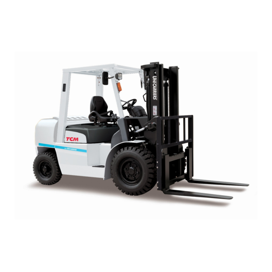
TCM~
. . . .  
W O R K S H O P   M A N U A L  
F O R K L I F T   TRUCK 
︿
︿
O
刃 ス
ω
O
Z
C
ト 一 一
F D 3 5 T 9  
F D 4 0 T 9  
F D 4 5 T 9  
F D 5 0 T 9  
F D 3 5 c 9  
F D 4 0 C 9  
F D 4 5 c 9  
F G 3 5 T 9  
F G 4 0 T 9  
H
U
U
2
u
a
H
O
ω
0
4
d
TCM  C O R P O R A T I O N  
Z
0 ・
m
明 ム
‑ ω
m
TCMc
O R A T I O

Advertisement

Table of Contents
loading

Summary of Contents for TCM FD35C9

  • Page 3 IMPORTANT For detailed procedures about operating the lift truck, see the lift truck “OPERATION AND MAINTENANCE MANUAL.” Improper operation of the lift truck might cause serious bodily injury or death to you or fellow workers. The decals on your lift truck indicate the level of hazard, such as “ CAUTION,”...
  • Page 4 (Empty page)
  • Page 5 INTRODUCTION INDEX TCM offers a wide variety of lift trucks which have 1. GENERAL been enthusiastically welcomed by users all over the world. The lift trucks covered in this Workshop Manual DESCRIPTION have also been developed through years of research and experience, and they feature high quality designs and 2.
  • Page 6 (Empty page)
  • Page 7: Table Of Contents

    1. GENERAL DESCRIPTION SAFETY INSTRUCTIONS ................1-1 BASIC SERVICING KNOWLEDGE ............1-17 LIST OF LUBRICANTS ................1-26 PRE-OPERATION INSPECTION ..............1-27 PERIODIC INSPECTIONS ................1-29...
  • Page 9: Safety Instructions

    1.1 SAFETY INSTRUCTIONS 1.1.1 Introduction ■ Lift trucks should only be operated by qualified operators (1) A qualified operator must have training and possess any required licenses to operate this truck. (2) The operation of a crane or performing any welding must be only attempted by qualified personnel.
  • Page 10 (4) Clear away any obstructions or hazards from the work area. (5) Do not stack unstable objects. Take any necessary measures to prevent any stacks of objects from collapsing. (6) Keep the areas around the switchboard, fire extinguisher, stairs, and emergency exits clear of obstacles.
  • Page 11 1.1.5 Maintenance precautions (while working) (1) Follow the specified work procedure. (2) Do not remove any covers or components other than those necessary to do the job. (3) Do not allow people other than service personnel to enter the work area.
  • Page 12 (6) Make certain all the switches on the electrical equipment you used have been turned off. (7) Use only TCM approved replacement parts and lubricants. (8) After servicing, make sure the truck operates properly. 1.1.7 Modifications to the truck might void your warranty Do not try to modify your truck.
  • Page 13 1.1.10 Safety rules for maintenance <Before starting maintenance> Before starting maintenance service, make sure: (1) The travel and load handling control levers are in neutral. (2) The parking brake is securely applied. (3) The wheels are blocked. (4) Put a sign stating “Do not operate” on the truck or mark the off-limits area around the truck with traffic cones or chains to keep people away from the work area.
  • Page 14 (4) Use jack stands, supporting blocks or a bench suitable for supporting Rectangular the truck: cross section · Do not use square timbers as supporting blocks. · Use only specified jack stands, supporting blocks or platform. · Use jack stands, supporting blocks and a bench that have enough strength for the purpose.
  • Page 15 (4) Chain blocks · Do not toss or drag a chain block. If a block becomes wet, wipe Do not drag! away the moisture and lubricate it properly. An elongated or Do not toss! deformed hook should not be used. ·...
  • Page 16 <Removing and reinstalling tires and rims> (1) Deflate the tire before loosening the bolts connecting the rims (for the split rim type) or before removing the side ring or lock ring (for the side ring type). (2) It is particularly dangerous if you try to remove an inflated tire from the truck with the split-rim having a loose or missing rim connecting bolt.
  • Page 17 <Precautions to take when overhauling cylinders> (1) Do not try to overhaul cylinders while they are mounted on the truck. Remove the cylinder assembly and overhaul it in a workshop. (2) When removing a cylinder from the truck, secure it to a mast connecting member with rope, to prevent it from falling.
  • Page 18 PLATE WING NUT stoppers. (8) Apply genuine TCM Chain Coat chain lubricant to the lift chains from the front of the mast with the forks lowered to the ground. (You can LEVER use engine oil for this purpose. Do not use grease.) <Opening the radiator cap>...
  • Page 19 <Electrical system> (1) Precautions when recharging batteries · Make sure the power cable is securely connected before turning on the battery charger. Do not disconnect or reconnect the power cable while the battery charger is on. · Loosen the cap on each cell in the battery. ·...
  • Page 20 <Welding> (1) Observe the following conditions when welding: · When welding near a tire, note that there is a danger of the tire exploding if it is heated excessively. · Do not try to weld or gas cut any container or pipe containing fuel or oil.
  • Page 21 <Grinding> (1) Put the specified safety cover on the grinding wheel. (2) The clearance between the workrest and the grinding wheel should be COVER SHIELD 3 mm [0.118 in.] less than 3 mm. WORKREST (3) Install a shield to prevent grinding powder from flying off. (4) Make a dry run on the grinding wheel for at least 1 minute before each use or for more than 3 minutes whenever the grinding wheel is replaced with a new one.
  • Page 22 <Transporting> (1) When a group is carrying a heavy load, make sure everyone understands the meaning of any hand signals and the communication methods that will be used. (Refer to “1.1.9. When working in a group”.) (2) Prevent back injuries. Use a diagonal foot position and get as close to the load as possible.
  • Page 23 (11) If a fire breaks out, observe the following precautions: · If a fire breaks out, give a loud warning to fellow workers immediately. · If an electrical device catches fire, turn off the power switch before trying to fight fire. ·...
  • Page 24 (15) The drive shaft and planet carrier should be installed by turning them. Do not push them or hit them. Be careful not to get your fingers pinched. (16) If it is hard to remove the HST motor sprocket in a Bobcat loader, BEARING PULLER do not hit the puller with force.
  • Page 25: Basic Servicing Knowledge

    1.2 BASIC SERVICING KNOWLEDGE 1. Installing bearings When installing a bearing onto a shaft, tap its inner race with a mallet as shown in Figure 1.1. When installing a bearing into a case, tap its outer race. When removing, use the same procedure as for installing.
  • Page 26 ③ When installing an oil seal onto a shaft, apply lubricating oil or grease to its seal lip and the mounting surface of the shaft. For a double-lip type, fill grease by 1/3 to 1/2 of the space between the lips. When inserting an oil seal into a case, use care to damage the seal lip.
  • Page 27 5. CLEANING ■ General metallic parts ① Clean parts thoroughly using cleaning fluid. It is recommended that parts be immersed in cleaning fluid and moved up and down slowly until all old lubricant and foreign material is dissolved and parts are thoroughly cleaned.
  • Page 28 6. STANDARD BOLT TIGHTENING TORQUE See the bolt torque charts on page 1-22 to 1-25 for the torques of standard bolts when they are used for general applications. Refer to the Shop Manual and Service Manual of your truck model when: 1) Special nuts are used.
  • Page 29 Division Surface Name Shape Thread size Material Part number by strength treatment Nominal symbol 01101- SS400 Black SS400 01100- “ M4 - M8 coarse and S45C 01103- “ Normal M10 - M39 fine Yellow SCM435, Boron steel 01106- “ chromate SCM435, Boron steel 10.9 01107-...
  • Page 30 1-22...
  • Page 31 1-23...
  • Page 32 1-24...
  • Page 33 1-25...
  • Page 34: List Of Lubricants

    Lubricant Prevailing ambient Location Grade of viscosity to be used temperature TCM Lube Life C-1 -25°C to 35°C [ -13°F to 95°F] Engine crankcase Engine oil TCM Lube Life S-3 0°C & above [32°F & above] TCM Lube Life X-3 0°C to -25°C [32°F to -13°F]...
  • Page 35: Pre-Operation Inspection

    1.4 PRE-OPERATION INSPECTION Component Item to be checked Checking procedure Engine ① Oil level. (A) Remove dipstick and wipe its end with clean cloth. Reinstall and keep it for about 1 minute. Remove it to check oil level. (B) Check for contamination of oil on the dipstick. ②...
  • Page 36 Component Item to be checked Checking procedure Steering wheel ① Wander, pull, hard (A) Run the truck at slow speed to check whether the steering. truck wanders or pulls to one side or has hard steering. Power steering ① Operation and oil leakage. (A) Run the truck at slow speed and turn steering wheel to the right and left to check power steering for operation and oil leakage from piping.
  • Page 37: Periodic Inspections

    Safety and Sanitation Regulations”) The items that must be inspected and serviced, and the procedures for doing so, are described in the TCM Inspection Service Notes. This requirement should be made clear to the customer when the forklift truck is delivered.
  • Page 38 Periodic inspection items and intervals 1000 1100 1200 Interval Hour Symbol: Item Month Procedure W: Disassemble Engine oil Oil level X X X X X X X X X X X X : Check Engine oil Contamination A A A A...
  • Page 39 1000 1100 1200 Interval Hour Symbol: Item Month Procedure C W: Disassemble Fuel pump -- strainer (diesel trucks) Contamination Starter motor brush -- : Check Wear commutator surface A: Adjust Generator brush -- commutator surface Wear O: Remove Carburetor Fuel leakage C...
  • Page 40 1000 1100 1200 Interval Hour Symbol: Item Month Procedure W: Disassemble Brake back plate Deformation : Check Brake back plate Cracks A: Adjust Brake back plate Damage O: Remove Parking brake Braking effect A A A A X: Replace Parking brake lever Travel T: Tighten Parking brake lever...
  • Page 41 1000 1100 1200 Interval Hour Item Symbol: Month Procedure Lights Operation W: Disassemble Switches Operation : Check Warning lights Function A: Adjust Horn Function O: Remove Turn signal Function X: Replace Turn signal lever Operation T: Tighten Hydraulic oil Level C: Clean X...
  • Page 42 1000 1100 1200 Interval Hour Symbol: Item Month Procedure W: Disassemble Retaining roller mounting bolts Looseness : Check Lift cylinder Operation A: Adjust Lift cylinder Oil leakage O: Remove Lift cylinder rod Damage X: Replace Tilt cylinder Operation T: Tighten Tilt cylinder Oil leakage C: Clean...
  • Page 43 2. REMOVING/REINSTALLING ELECTRICAL PARTS ..................2-1 2.1.1 HEAD LAMP ....................2-1 2.1.2 FRONT COMBINATION LAMP ..............2-2 2.1.3 REAR COMBINATION LAMP ..............2-3 2.1.4 BATTERY .....................2-4 HOOD AND OVERHEAD GUARD ..............2-10 ENGINE HOOD ....................2-15 COUNTERWEIGHT ..................2-18 MUFFLER ......................2-20 RADIATOR .......................2-22 AIR CLEANER ....................2-25 FRONT GUARD ....................2-27 2.9A BRAKE PEDAL (automatic transmission trucks) ..........2-31 2.9B BRAKE PEDAL AND CLUTCH PEDAL (manual transmission trucks) ..2-34 2.10 ENGINE AND DRIVE UNIT ................2-37...
  • Page 45: Electrical Parts

    2.1 ELECTRICAL PARTS 2.1.1 HEAD LAMP ■ REMOVAL ① Disconnect the connector of the head lamp from the connector of the wire harness (1) on the overhead guard. Fig. 2.1 ② Remove the nut (1) and the washer (2). Remove the head lamp (4) from the overhead guard (3).
  • Page 46: Front Combination Lamp

    2.1.2 FRONT COMBINATION LAMP ■ REMOVAL ① Disconnect the connector of the front combination lamp from the connector of the wire harness (1) on the overhead guard. Fig. 2.5 ② Remove the two screws (1) and then remove the front combination lamp (3) from the overhead guard (2).
  • Page 47: Rear Combination Lamp

    2.1.3 REAR COMBINATION LAMP ■ REMOVAL ① Remove the screws (1) and then remove the rear combination lamp (2) from the overhead guard (3). Fig. 2.9 ② D i s c o n n e c t t h e c o n n e c t o r o f t h e r e a r combination lamp (2) from the connector of the wire harness (1) on the overhead guard.
  • Page 48: Battery

    2.1.4 BATTERY ■ REMOVAL (diesel trucks) ① Disconnect the negative (-) battery cable (3) from the negative (-) terminal (2) of the battery 2 (1). Make sure to disconnect the negative (-) battery cable first. Fig. 2.13 ② Disconnect the positive (+) battery cable (3) from the positive (+) terminal (2) of the battery 1 (1).
  • Page 49 ④ Remove the nut (2), spring washer (3) and washer (4) from the battery 1’s anchor bolt (1), and then remove the battery holder (5). Fig. 2.16 ⑤ Remove the nut (2), spring washer (3) and washer (4) from the battery 2’s anchor bolt (1), and then remove the battery holder (5).
  • Page 50 ■ REINSTALLATION (diesel trucks) ① Put the batteries 1 (1) and 2 (2) in place. Pay attention to the direction of the terminals. Fig. 2.19 ② Install the battery holder (2) and anchor bolt (3) on the battery 2 (1), and secure them using the nut (4), spring washer (5), and washer (6).
  • Page 51 ④ Connect the battery cable (3) to the battery 1’s negative (-) terminal (1) and the battery 2’s positive (+) terminal (2). Fig. 2.22 ⑤ Connect the positive (+) battery cable (2) to the battery 1’s positive (+) terminal (1). Make sure to connect the battery cable to the positive (+) terminal of the battery first.
  • Page 52 ■ REMOVAL (gasoline trucks) ① Disconnect the negative (-) battery cable (2) from the battery’s negative (-) terminal (1). Make sure to disconnect the negative (-) battery cable first. Fig. 2.25 ② Disconnect the positive (+) battery cable (2) from the battery’s positive (+) terminal (1). Fig.
  • Page 53 ■ REINSTALLATION (gasoline trucks) ① Put the battery (1) in place. Fig. 2.29 ② Install the battery holder (1) and anchor bolt (2), and secure them using the nut (3), spring washer (4), and washer (5). 2.9 - 4.8 N-m {0.3 - 0.5 kgf-m} [2.1 - 3.5 lbf-ft] Fig.
  • Page 54: Hood And Overhead Guard

    2.2 HOOD AND OVERHEAD GUARD The following procedure involves removing the fuel tank hose. Make sure to keep flammable materials away from the area. ■ REMOVAL ① Park the truck according to the specified procedure. (See “1.1.10 Safety rules for maintenance”, <Before starting maintenance>) ②...
  • Page 55 ⑥ Remove the connectors of the overhead guard wire harness (front) (1) from the connectors of the front guard wire harness. Fig. 2.36 ⑦ Remove the connectors of the overhead guard wire harness (rear) (1) from the connectors of the engine wire harness. Fig.
  • Page 56 ⑨ Remove the bolts (1) securing the overhead guard. Fig. 2.39 ⑨ Hoist the overhead guard (1) off from the frame with the wire ropes attached to sections 154 kg [340 lbs] Fig. 2.40 2-12...
  • Page 57 ■ REINSTALLATION ① Hoist the overhead guard (1) with the wire ropes attached to sections A. Then install the overhead guard (1) on the frame (2). 154 kg [340 lbs] Fig. 2.41 ② Secure the overhead guard (2) using the bolts (1).
  • Page 58 ④ Connect the connectors of the overhead guard wire harness (front) (1) to the connectors of the front guard wire harness (2). Fig. 2.44 ⑤ Install both side covers (1) on the front guard. 5 N-m {0.5 kgf-m} [3.7 lbt-ft] Fig.
  • Page 59: Engine Hood

    2.3 ENGINE HOOD ■ REMOVAL ① Remove the overhead guard. (See “2.2 HOOD AND OVERHEAD GUARD.”) ② Remove the clip (3) and washer (4) securing the gas spring (1) to the overhead guard (2). Fig. 2.46 ③ Raise the engine hood so that the gas spring (1) is fully stretched.
  • Page 60 ④ Unlock the engine hood (1) and then lower it carefully. Fig. 2.48 ⑤ Remove the bolts (2) securing the bracket (1) in place. Then, remove the bracket (1) and engine hood (3) together. Fig. 2.49 2-16...
  • Page 61 ■ REINSTALLATION ① Fit the bracket (1) to the overhead guard’s rear legs (2), and then secure them using the bolts (3). 21.2 N-m {2.16 kgf-m} [15.6 lbf-ft] Fig. 2.50 ② Raise the engine hood (1). Keep the engine hood raised by fastening it to the overhead guard (2) using a rope.
  • Page 62: Counterweight

    2.4 COUNTERWEIGHT ■ REMOVAL ① Pass a wire rope (2) through each hole in the counterweight (1) and then attach a ring to each end of the wire rope. Fig. 2.53 ② Remove the bolts (1), spring washers (2), and washers (3) securing the counterweight.
  • Page 63 ■ REINSTALLATION ① Hoist the counterweight (1) and place it in its mounting position at the rear section of the frame (2). Align section A of the frame with the recess of the counterweight. (kg [lbs]) 3.5 tons 2044 [4506] 4.0 tons 2474 [5454] 4.5 tons...
  • Page 64: Muffler

    2.5 MUFFLER ■ REMOVAL ① Remove the counterweight. (See “2.4 COUNTERWEIGHT.”) ② Remove the bolt (1) and nut (2) securing the muffler, and remove the washers (3) and cushions (4). Fig. 2.58 ③ Remove the nut (1) on the engine-side flange, and then remove the muffler (2). Fig. 2.59 2-20...
  • Page 65 ■ REINSTALLATION ① Install the muffler-side flange onto the stud of the exhaust manifold flange. ② Secure the muffler using the cushions (1), bolt (2), washers (3) and nut (4). Install the nut (5) on the engine-side flange. Nut (4): 11 N-m {1.1 kgf-m} [8.1 lbf-ft] Nut (5): 21.2 N-m {2.16 kgf-m} [15.6 lbf-ft] Fig. 2.60 ③ I n s t a l l t h e c o u n t e r w e i g h t . ( S e e “ 2 . 4 COUNTERWEIGHT.”) 2-21...
  • Page 66: Radiator

    2.6 RADIATOR ■ REMOVAL ① Remove the radiator cover (1). Fig. 2.61 ② Remove the counterweight. (See “2.4 COUNTERWEIGHT.”) ③ Drain the coolant. ④ Remove the radiator hoses (1). For an automatic transmission truck, remove the oil cooler hose as well. Tag all hoses for proper reinstallation.
  • Page 67 ⑥ Remove the fan shroud mounting bolts (1) and then separate the fan shroud (3) from the radiator (2). Bring the removed fan shroud near the engine. Fig. 2.64 ⑦ Remove the bolts (1), washers (2), rubber cushions (3), and nuts (4) that secure the radiator in place, and then remove the radiator (5).
  • Page 68 ③ Install the radiator (2) with the rubber cushions (1) and then secure it using the bolts (3), washers (4), and nuts (5). 7.8 - 11.7 N-m {0.8 - 1.2 kgf-m} [5.8 - 8.6 lbf-ft] Fig. 2.68 ④ Align the hook of the fan shroud (1) with the guide located at the center of the tank of the radiator (2).
  • Page 69: Air Cleaner

    2.7 AIR CLEANER ■ REMOVAL Do not start the engine with the air cleaner removed. ① Open the engine hood and then lock the gas spring securely. ② Remove one end of the hose (1) leading to the engine, from the air cleaner (2). Cover the opening end of the hose.
  • Page 70 ■ REINSTALLATION ① Install the air cleaner (1) on the bracket (2) using the bolts (3). 7.8 to 11.7 N-m {0.8 to 1.2 kgf-m} [5.8 - 8.6 lbf-ft] Fig. 2.75 ② Connect one end of the plastic duct (1) leading from the rear pipe, to the air cleaner (2).
  • Page 71: Front Guard

    2.8 FRONT GUARD ■ REMOVAL ① Remove the overhead guard. (See “2.2 HOOD AND OVERHEAD GUARD.”) ② Remove the steering wheel. (See “2.13 STEERING WHEEL.”) ③ Disconnect the connectors of the front guard wire harness (1) from the connectors of the engine wire harness (2).
  • Page 72 ⑧ Remove the wiring to the parking brake switch. ⑨ Remove the brake oil reservoir. Note: The reservoir should be removed with brake oil in it. ⑩ Remove the bolts (3) that secure the pipes (2) leading to the tilt cylinders (1), to the front guard.
  • Page 73 ■ REINSTALLATION ① Hoist the front guard (1) and place it in the mounting position in the front of the frame. 40 kg [88 lbs] ② Secure the front guard (1) using the four bolts (2), spring washers (3) and washers (4) at the right and left sides of the front guard.
  • Page 74 ⑦ Install the valve levers (1) on the front guard using the bolts (2). Fig. 2.86 ⑧ Connect the connectors of the front guard wire harness (1) to the connectors of the engine wire harness (2). Fig. 2.87 ⑨ Install the floorboard kit (1). Fig.
  • Page 75: A Brake Pedal (Automatic Transmission Trucks)

    2.9A BRAKE PEDAL (automatic transmission trucks) ■ REMOVAL ① Remove the floorboard kit. (See “2.8 FRONT GUARD.”) ② Remove the brake pipes (2) from the brake booster (1). Fig. 2.89 ③ Remove the high-pressure hose (2) from the brake booster (1). Remove the two return hoses (3) from the brake booster (1). Fig.
  • Page 76 ⑤ Remove the pedal assembly (2) from the transmission (1). Fig. 2.92 ■ REINSTALLATION ① Install the pedal assembly (1) on the transmission (2). 21.2 N-m {2.16 kgf-m} [15.6 lbf-ft] Fig. 2.93 ② Install the connecting rod (2) on the linkage (1).
  • Page 77 ③ Install the brake pipes (2) on the brake booster (1). Fig. 2.95 ④ Install the high-pressure hose (2) on the brake booster (1). Install the two return hoses (3) on the brake booster (1). Fig. 2.96 ⑤ Install the floorboard kit. (See “2.8 FRONT GUARD.”) 2-33...
  • Page 78: B Brake Pedal And Clutch Pedal (Manual Transmission Trucks)

    2.9B BRAKE PEDAL AND CLUTCH PEDAL (manual transmission trucks) ■ REMOVAL ① Remove the floorboard kit. (See “2.8 FRONT GUARD.”) ② Remove the split pin (1), washer (2) and pin (3), and then remove the clutch release cylinder (5) from the arm (4). Fig. 2.97 ③ Remove the brake pipes (2) from the brake booster (1).
  • Page 79 ⑤ Remove the return hoses (3) from the brake booster (1) and clutch booster (2). Fig. 2.100 ⑥ Remove the pedal assembly (2) from the transmission (1). Fig. 2.101 ■ REINSTALLATION ① Install the pedal assembly (1) on the transmission (2). 21.2 N-m {2.16 kgf-m} [15.6 lbf-ft] Fig.
  • Page 80 ② Connect the clutch release cylinder (1) and the arm (2) using the pin (3), and secure them using the washer (4) and split pin (5). Fig. 2.103 ③ Install the brake pipes (2) on the brake booster (1). Fig. 2.104 ④...
  • Page 81: Engine And Drive Unit

    2.10 ENGINE AND DRIVE UNIT ■ REMOVAL ① Park the truck. ② Remove the wheels. ③ Remove the mast assembly. (See “2.17 MAST ASSEMBLY.”) ④ Remove the overhead guard and hood. (See “2.2 HOOD AND OVERHEAD GUARD.”) ⑤ Remove the counterweight. (See “2.4 COUNTERWEIGHT.”) ⑥...
  • Page 82 ⑮ Remove the battery. (See “2.1.4 BATTERY.”) ⑯ Remove each wiring from the engine. ・Starter wiring STARTER WIRING STARTER WIRING ・Alternator wiring ALTERNATOR WIRING ALTERNATOR WIRING ・Oil pressure switch wiring OIL PRESSURE SWITCH WIRING OIL PRESSURE SWITCH WIRING ・Temperature sender wiring TEMPERATURE SENDER WIRING TEMPERATURE...
  • Page 83 ・Grounding ・Distributor wiring (for TB42 only) DISTRIBUTOR WIRING ・Fuel cut valve wiring FUEL CUT VALVE WIRING FUEL CUT VALVE WIRING ・Glow plug wiring (for S6S only) GLOW PLUG WIRING ・Sedimenter wiring (for S6S only) SEDIMENTER WIRING 2-39...
  • Page 84 <For an automatic transmission truck> ⑰ Disconnect the wiring from the solenoid valve in the transmission control valve assembly. ⑱ Disconnect the oil cooler hoses (1) from the transmission case (2). Fig. 2.108 <For a manual transmission truck> ⑲ Disconnect the oil cooler hoses (1) from the transmission case (2).
  • Page 85 Remove the mounting bolt (1), washers (2), cushions (3), and nut (4). Fig. 2.111 Remove the bolts (1) and washers (2). Then remove the axle support caps (3). Fig. 2.112 Slowly hoist the engine and drive unit assembly and remove it. Be careful not to damage other parts.
  • Page 86 ■ REINSTALLATION ① Lift the engine (1) and drive unit (2) over the frame together, and carefully lower them in the mounting position. 1100 kg [2425 lbs] Fig. 2.114 ② Secure the engine and drive unit using the cushions (1), mount bolt (2), washers (3), and nut (4).
  • Page 87 ③ Install the axle support caps (1) using the bolts (2) and washers (3). 175 N-m {17.8 kgf-m} [129.1 lbf-ft] Apply LOCTITE #572. Fig. 2.116 <For an automatic transmission truck> ④ C o n n e c t t h e w i r e h a r n e s s ( 2 ) t o t h e transmission solenoid valve (1).
  • Page 88 <For a manual transmission truck> ⑥ Connect the oil cooler hoses (1) to the transmission case (2). Fig. 2.119 ⑦ Connect the wire harness to the neutral switch (1) and the reverse switch (2). Fig. 2.120 2-44...
  • Page 89 ⑧ Connect the wire harness to each part of the engine. ・Starter wiring STARTER WIRING STARTER WIRING ・Alternator wiring ALTERNATOR WIRING ALTERNATOR WIRING ・Oil pressure switch wiring OIL PRESSURE SWITCH WIRING OIL PRESSURE SWITCH WIRING ・Temperature sender wiring TEMPERATURE SENDER WIRING TEMPERATURE SENDER WIRING 2-45...
  • Page 90 ・Grounding ・Distributor wiring (for TB42 only) DISTRIBUTOR WIRING ・Fuel cut valve wiring FUEL CUT VALVE WIRING FUEL CUT VALVE WIRING ・Glow plug wiring (for S6S only) GLOW PLUG WIRING ・Sedimenter wiring (for S6S only) SEDIMENTER WIRING 2-46...
  • Page 91 ⑨ Connect the suction hose (2) leading to the pump (1). Fig. 2.121 ⑩ Install the front plate on the frame. ⑪ Connect the fuel hose to the engine. ⑫ Install the propeller shafts on the engine. ⑬ Install the front guard and the floorboard kit. (See “2.8 FRONT GUARD.”) ⑭ Install the accelerator cable on the front plate.
  • Page 92: Drive Axle

    2.11 DRIVE AXLE ■ REMOVAL ① Jack up the front end of the truck and support the truck frame with a support stand (1). Place blocks (2) on each rear wheel. Fig. 2.122 ② Remove the wheels. ③ Remove the mast assembly. (See “2.17 MAST ASSEMBLY.”) ④...
  • Page 93 ⑦ Remove the axle shafts (1). Fig. 2.125 ⑧ Support the transmission and then remove the bolts (1) that connect the drive axle to the transmission. Fig. 2.126 ⑨ Support the drive axle with a crane and wire ropes. Fig. 2.127 ⑩...
  • Page 94 ■ REINSTALLATION ① Hold the drive axle (1) near the position of the frame where the drive axle is to be installed. ② Apply liquid gasket to the fitting surface of the drive axle (1), and then install the drive axle (1) on the transmission (2).
  • Page 95 ⑥ Connect the parking brake cables (1) to the brake lever (2). Fig. 2.133 ⑦ Add gear oil. ⑧ Install the mast assembly. (See “2.17 MAST ASSEMBLY.”) ⑨ Install the wheels. ⑩ Remove the support stand. 2-51...
  • Page 96: Steering Axle

    2.12 STEERING AXLE ■ REMOVAL ① Jack up the rear wheels and support the frame of the truck with a stand (1). Place blocks (2) on each front wheel. Fig. 2.134 ② Remove the counterweight. (See “2.4 COUNTERWEIGHT.”) ③ Remove the wheels. ④ Remove the ball joint (3) of the steering cylinder rod (2) from the center arm (1).
  • Page 97 ⑥ Support the underside of the steering axle (1) with a garage jack. Then remove the bolts (3) and spring washers (4) that secure the axle supports (2) in place. Fig. 2.137 ⑦ Gradually lower the garage jack and remove the steering axle (1) from the frame (2).
  • Page 98 ③ Secure the steering axle (4) in place by installing the front and back axle supports (1) on the frame using the bolts (2) and spring washers (3). 175 N-m {17.8 kgf-m} [129.1 lbf-ft] Apply LOCTITE #578. Fig. 2.140 ④ Install the ball joint (3) of the drag link (2) on the center arm (1).
  • Page 99: Steering Wheel

    2.13 STEERING WHEEL ■ REMOVAL ① Remove the bolts (1), and then remove the covers A (2) and B (3). Fig. 2.143 ② R e m o v e t h e b o l t s ( 1 ) a n d m o v e t h e combination meter assembly (2) toward the front guard side.
  • Page 100 ④ Remove the bolt (1) and washer (2). Then remove the steering wheel lock lever (3). Fig. 2.146 ⑤ Remove the lock bolt (1) and washer (2). Fig. 2.147 ⑥ Remove the bolts (1) and bushings (2). Then remove the steering wheel assembly (3). Fig.
  • Page 101 ■ REINSTALLATION ① Install the universal joint (1) on the spline shaft (2) in the steering gear box. Then, install the steering wheel assembly (5) on the front guard (6) and secure it using the bushings (3) and bolts (4). 21.2 N-m {2.16 kgf-m} [15.6 lbf-ft] Fig.
  • Page 102 ④ C o n n e c t t h e w i r e h a r n e s s ( 2 ) t o t h e combination switch (1). Fig. 2.152 ⑤ Install the combination meter (1) and cover C (2) on the steering wheel column (3) using the bolts (4).
  • Page 103: Tilt Cylinder

    2.14 TILT CYLINDER When disassembling or reassembling the tilt cylinder, make sure to support the outer channel of the mast using a crane and wire ropes. ■ REMOVAL ① Remove the plastic covers (1) and then remove the tilt cylinder covers (2). Fig.
  • Page 104 ④ Remove the bolts (1) and remove the connecting pins (2) from the frame. Then remove the tilt cylinders (3). Fig. 2.158 ■ REINSTALLATION ① Place each tilt cylinder (2) in the mounting position on the frame. Pay attention to the positions of the right and left hydraulic ports (1).
  • Page 105 ④ Connect the hydraulic hoses (2) to each tilt cylinder (1). Fig. 2.162 ⑤ Install the tilt cylinder covers (1) and plastic covers (2). Fig. 2.163 2-61...
  • Page 106: Main Pump

    2.15 MAIN PUMP ■ REMOVAL ① Drain the oil from the oil tank. ② Remove the counterweight. (See “2.4 COUNTERWEIGHT.”) ③ Disconnect the hose (1) from the main pump (2) that leads to the oil tank. Fig. 2.164 ④ Disconnect the hoses (1) from the main pump (2), one leading to the control valve and the other to the priority valve.
  • Page 107 ■ REINSTALLATION ① Install the main pump (1) on the mounting bracket (2) section and then secure it using the bolts (3), spring washers (4), washers (5) and nuts (6). 33.8 – 50.9 N-m {3.5 – 5.2 kgf-m} [24.9 – 37.5 lbf-ft] Fig.
  • Page 108: Control Valve

    2.16 CONTROL VALVE ■ REMOVAL ① Remove the pin (1), washer (2), and cotter pin (3). Then remove the rod (4) from each spool. Fig. 2.170 ② Disconnect the hoses (2) from the control valve (1). Temporarily secure each return hose with its end at a level that is higher than the oil level in the tank.
  • Page 109 ■ REINSTALLATION ① Install the control valve (1) on the front plate (2). Then secure it using the bolts (3) and nuts (4). 27.7 - 41.5 N-m {2.8 - 4.2 kgf-m} [20.4 - 30.6 lbf-ft] Apply LOCTITE #262 or SCOTCH GRIP 2352 to the threads of the bolts (3).
  • Page 110: Mast Assembly

    2.17 MAST ASSEMBLY ■ REMOVAL ① Slightly support the top cross-member of the outer channel of the mast assembly using a crane. ② Remove the bolts (1) and plate (2). Then remove the mast-side connecting pin (4) of the tilt cylinder (3). Fig.
  • Page 111 ⑤ Remove the mast assembly by lifting it with a crane. 3.5 tons, 4.0 tons 980 kg [2161 lbs] 4.5 tons 1120 kg [2469 lbs] 5.0 tons 1250 kg [2756 lbs] (For a standard mast assembly with a lifting height of 3 m) ■...
  • Page 112 ⑤ Connect the hoses (2) to the lift cylinders (1). Fig. 2.182 2-68...
  • Page 113 3. DISASSEMBLY AND REASSEMBLY 3.1 CLUTCH PEDAL AND BRAKE PEDAL ..............3-1 3.1.1 BRAKE PEDAL (automatic transmission trucks) ........... 3-1 3.1.2 CLUTCH PEDAL AND BRAKE PEDAL (manual transmission trucks) ....3-5 3.1.3 CLUTCH BOOSTER ....................3-9 3.1.4 BRAKE BOOSTER ....................3-15 3.2 DRIVE UNIT ........................
  • Page 115: Clutch Pedal And Brake Pedal

    3.1 CLUTCH PEDAL AND BRAKE PEDAL 3.1.1 BRAKE PEDAL (automatic transmission trucks) ■ DISASSEMBLY ① Remove the springs (3) from the brake pedal (1) and inching pedal (2). Fig. 3.1 ② Remove the split pins (1), washers (2), and pins (3). Then remove the joint (5) and inching rod (6) from the linkage (4).
  • Page 116 ④ Remove the linkage (2) from the pedal bracket (1). Fig. 3.4 ⑤ Remove the split pin (1), washer (2), and pin (3) from the brake booster (4). Fig. 3.5 ⑥ Remove the bolt (1) and remove the shaft (2). Then remove the brake pedal (4) and inching pedal (5) from the pedal bracket (3).
  • Page 117 ■ REASSEMBLY ① Install the brake booster (2) on the pedal bracket (1) using the bolts (3). 21.2 N-m {2.2 kgf-m} [15.6 lbf-ft] Fig. 3.8 ② Place the brake pedal (1) and inching pedal (2) in the pedal bracket (3) and then secure them using the shaft (4).
  • Page 118 ④ Place the linkage (1) and spacers (2) in the pedal bracket (3). Then secure them using the shaft (4). M8: 9.8 N-m {1.0 kgf-m} [7.2 lbf-ft] M6: 4.0 N-m {0.4 kgf-m} [3.0 lbf-ft] Fig. 3.11 ⑤ Install the joint (2) and inching rod (3) on the linkage (1) using the pins (4), washers (5), and split pins (6).
  • Page 119: Clutch Pedal And Brake Pedal (Manual Transmission Trucks)

    3.1.2 CLUTCH PEDAL AND BRAKE PEDAL (manual transmission trucks) ■ DISASSEMBLY ① Remove the pipe (3) connecting the clutch release cylinder (1) and the clutch booster (2). Fig. 3.14 ② Remove the bolts (1) and remove the clutch release cylinder (2). Fig.
  • Page 120 ④ Remove the split pins (3) from the clutch booster (1) and brake booster (2), and then remove the pins (4) and washers (5). Fig. 3.17 ⑤ Remove the bolts (1) and then remove the clutch booster (2) and brake booster (3). Fig.
  • Page 121 ■ REASSEMBLY ① Place the brake pedal (1) and clutch pedal (2) in the pedal bracket (3). Then secure them to the bracket using the shaft (4). 9.8 N-m {1.0 kgf-m} [7.2 lbf-ft] Fig. 3.20 ② Install the clutch booster (1) and brake booster (2) on the pedal bracket (4) using the bolts (3).
  • Page 122 ④ Install the springs (3) on the brake pedal (1) and clutch pedal (2). Fig. 3.23 ⑤ Install the clutch release cylinder (2) on the pedal bracket (1) using the bolts (3). 21.2 N-m {2.2 kgf-m} [15.6 lbf-ft] Fig. 3.24 ⑥...
  • Page 123: Clutch Booster

    3.1.3 CLUTCH BOOSTER Have a repair kit handy before starting the disassembly. Use the new parts from the kit during reassembly. ■ DISASSEMBLY ① Remove the push rod assembly (2) along with the boot (1). Fig. 3.26 ② Slightly push in the guide assembly (1) and remove the stopper ring (2).
  • Page 124 ④ Remove the bolt (1) and gasket (2). Fig. 3.29 ⑤ Slightly push in the master cylinder piston (1) and remove the pin (2). Then remove the master cylinder piston (1) and spring (3). Fig. 3.30 ⑥ Remove the snap ring (1) and remove the plug (2), spring (3), and spool (4).
  • Page 125 2) Remove the reaction piston 1 (2) from the power piston (1). Fig. 3.33 3) Remove the reaction piston 2 (1) and spring (2) from the power piston (3). Fig. 3.34 4) Remove the snap ring (1) and remove the plug (3), spring (4), and control valve (5) from the power piston (2).
  • Page 126 ■ REASSEMBLY ① Reassembling the reaction piston 1) Insert the control valve (1), spring (2), and plug (3) into the power piston (4). Then install the snap ring (5). Fig. 3.37 2) Install the spring (2) onto the reaction piston 1 (1).
  • Page 127 5) Install the guide assembly (2) on the reaction piston 1 (1). Fig. 3.41 ② Install the spring (1) and master cylinder piston (2) on the cylinder section. Pushing in the master cylinder piston (2), install the pin (3). Fig. 3.42 ③...
  • Page 128 ⑤ Install the spool (1), spring (2), and plug (3). Then install the snap ring (4). Fig. 3.45 ⑥ Install the push rod (1) along with the boot (2). Fig. 3.46 3-14...
  • Page 129: Brake Booster

    3.1.4 BRAKE BOOSTER Have a repair kit handy before starting the disassembly. Use the new parts from the kit during reassembly. ■ DISASSEMBLY ① Remove the push rod assembly (2) along with the boot (1). Fig. 3.47 ② Slightly push in the guide assembly (1) and remove the stopper ring (2).
  • Page 130 ④ Remove the bolt (1) and gasket (2). Fig. 3.50 ⑤ Slightly push in the master cylinder piston (1) and remove the pin (2). Then remove the master cylinder piston (1) and spring (3). Fig. 3.51 ⑥ Remove the snap ring (1) and remove the plug (2), spring (3), and spool (4).
  • Page 131 2) Remove the reaction piston 1 (2) from the power piston (1). Fig. 3.54 3) Remove the reaction piston 2 (1) and spring (2) from the power piston (3). Fig. 3.55 4) Remove the snap ring (1) and remove the plug (3), spring (4), and control valve (5) from the power piston (2).
  • Page 132 ■ REASSEMBLY ① Reassembling the reaction piston 1) Insert the control valve (1), spring (2), and plug (3) into the power piston (4). Then install the snap ring (5). Fig. 3.58 2) Install the spring (2) onto the reaction piston 1 (1).
  • Page 133 5) Install the guide assembly (2) on the reaction piston 1 (1). Fig. 3.62 ② Install the spring (1) and master cylinder piston (2) on the cylinder section. Pushing in the master cylinder piston (2), install the pin (3). Fig. 3.63 ③...
  • Page 134 ⑤ Install the spool (1), spring (2), and plug (3). Then install the snap ring (4). Fig. 3.66 ⑥ Install the push rod (1) along with the boot (2). Fig. 3.67 3-20...
  • Page 135: Drive Unit

    3.2 DRIVE UNIT 3.2.1 TORQUE CONVERTER TYPE TRANSMISSION ■ DISASSEMBLING THE UNIT ① Remove the torque converter assembly (1). Fig. 3.68 ② Remove the transmission control valve (1). Note: Remove the old gaskets from the mating surfaces. Use caution to prevent gasket scraps from entering the oil or screw holes.
  • Page 136 ④ Separate the transmission from the converter housing. Remove the output gear. Note: Remove the old gaskets from the mating surfaces. Use caution to prevent gasket scraps from entering the oil or screw holes. Fig. 3.71 ■ DISASSEMBLING CONVERTER HOUSING ① Remove the charging pump (1) from the converter housing.
  • Page 137 ■ REASSEMBLING TORQUE CONVERTER HOUSING ① With a gasket, install the charging pump (1) on the torque converter housing. Fig. 3.75 ② Install the strainer (1) on the converter housing. With an “O”-ring (2) and gasket (3), install the cover (4). Fig.
  • Page 138 ■ DISASSEMBLING TRANSMISSION ① Remove the forward/reverse clutch pack (1) and 2nd clutch pack (2) from the transmission case. Fig. 3.78 ② Remove the counter gear (1) from the transmission case. Fig. 3.79 ③ Remove the suction pipe (1) from the transmission case.
  • Page 139 ■ REASSEMBLING TRANSMISSION ① Install the suction pipe (1) on the transmission case. (for 43E-25 only) Note: The suction pipe (1) is not used with the 44E-25. Fig. 3.81 ② Install the counter gear (1) in the transmission case. Fig. 3.82 ③...
  • Page 140 ⑤ With a gasket, install the torque converter housing on the transmission case. Note: Pay attention to the engagement of the gears. There are three types of bolts with different lengths. For their respective locations, see Fig. 3.86. Fig. 3.85 A : 30 mm [1.18 in] long, 10 pcs.
  • Page 141 ■ DISASSEMBLING CLUTCH PACK The explanation given below is made using the forward/reverse clutch pack. The explanation about other clutch packs is omitted because they are similar in construction to the forward/reverse clutch pack. ① Remove the three seal rings (1) from the shaft. Fig.
  • Page 142 ④ Remove the end plate (1). Fig. 3.92 ⑤ Remove the clutch discs (friction plates (1) and separator plates (2)). Friction plates Separator plates Fig. 3.93 ⑥ Using a jig (1), compress the return spring Press and remove the snap ring from the groove. Release the compression slowly and remove the snap ring (2), retainer (3), and return spring (4).
  • Page 143 ⑦ Remove the piston (1) from the clutch drum. Fig. 3.96 ⑧ Remove the seal ring (1) from the piston. Fig. 3.97 ⑨ Remove the seal ring (1) from the shaft. Fig. 3.98 ⑩ Follow the same steps for disassembling the reverse clutch pack and the 2nd clutch pack.
  • Page 144 ■ REASSEMBLING CLUTCH PACK The explanation given below is made using the forward/reverse clutch pack. The explanation about other clutch packs is omitted because they are similar in construction to the forward/reverse clutch pack. ① Install the seal ring (1) on the outer diameter of the piston.
  • Page 145 Press Fig. 3.103 ⑤ Install the clutch discs (five separator plates (1) and five friction plates (2)) as follows: Install one separator plate first and then one friction plate. Keep installing pairs of plates in that order, ending with a separator plate. Friction plates Separator plates Fig. 3.104 ⑥ Install the end plate (1) and secure with the snap ring (2). Fig.
  • Page 146 ⑧ Install the thrust washer (1) and bearing (2). Fig. 3.107 ⑨ Install the seal rings (1). Fig. 3.108 ⑩ Follow the same steps for reassembling the reverse clutch pack and 2nd clutch pack. 3-32...
  • Page 147 ■ DISASSEMBLING CHARGING PUMP ① Remove the bolts assembling the charging pump. Fig. 3.109 ② Separate the case (1) from the stator support (2). Fig. 3.110 ③ Remove the drive gear (1) and driven gear (2) from the case. Fig. 3.111 ④...
  • Page 148 ■ REASSEMBLING CHARGING PUMP ① Install the seal ring (1) on the case. Fig. 3.113 ② Install the oil seal (2) on the case (1). Fig. 3.114 ③ Install the drive gear (1) and driven gear (2) on the case. Fig. 3.115 ④...
  • Page 149 ■ DISASSEMBLING CONTROL VALVE ① Remove the forward/reverse solenoid valve (1) and 2nd solenoid valve (2) from the valve body. Fig. 3.117 ② Remove the front cover (1). Fig. 3.118 ③ Remove the accumulator piston (1), three springs (2) and stopper (3). Fig.
  • Page 150 ⑤ Remove the inching valve piston (1) and spring (2). Fig. 3.121 ⑥ Remove the inching spool (1) along with the spring (2). Fig. 3.122 ⑦ Remove the speed range selector spool (2nd) (1) and spring (2) from the valve body. Fig.
  • Page 151 ■ REASSEMBLING CONTROL VALVE ① Install the selector spool (1) and the spring (2) in the valve body. Fig. 3.124 ② Install the accumulator springs (outer (1), middle (2), inner (3)) in that order, and then install the pin (4) and piston (5). Fig.
  • Page 152 ⑤ Install the piston (1) and spring (2) to the back of the inching spool. Fig. 3.128 ⑥ Install the front cover (2) with a gasket (1) into the valve body. Fig. 3.129 ⑦ Install the directional solenoid valve (1) onto the valve body.
  • Page 153 ■ DISASSEMBLING DIFFERENTIAL ① Remove the bearing cap stopper (1). Fig. 3.132 ② Remove the split pin (1) and nuts (2) and remove the bearing cap (3). Fig. 3.133 ③ Remove the cross case assembly. Fig. 3.134 ④ Remove the drive pinion assembly (1). Note: Record the type and number of shims.
  • Page 154 ⑤ Disassembling cross case 1) Remove the ring gear (1) from the cross case assembly. Fig. 3.136 2) Put the cross case upright with the flange half upward and remove the assembling bolts and nuts. Fig. 3.137 3) Separate the cross case into the flange half and the plain half. Remove the side gears (1) and pinion gears (2).
  • Page 155 ⑥ Disassembling drive pinion assembly 1) Extend the caulked part (1) of the lock nut outward. Fig. 3.139 2) Remove the lock nut. Fig. 3.140 3) Remove the drive pinion from the bearing Press cage. Fig. 3.141 3-41...
  • Page 156 4) Remove the shims (1) and spacer (2) from the drive pinion. Note: Record the type and number of shims. Fig. 3.142 5) Remove the outside bearing cup (1) and oil Press seal (2) from the bearing cage. Fig. 3.143 6) Remove the bearing cup (1) from inside the bearing cage.
  • Page 157 ■ REASSEMBLING DIFFERENTIAL ① Reassembling drive pinion 1) Install the oil seal (2) on the bearing cage (1). Note: Pay attention to the direction of the oil seal when installing it. Fig. 3.145 2) Install the inside and outside bearing cups (1) on the bearing cage.
  • Page 158 4) Install the “O”-ring (2) on the inner diameter of the spacer (1). Fig. 3.148 5) Install the spacer (1) and shims (2) on the drive pinion. Note: Install the same number and type of shims as removed. Fig. 3.149 6) Install the bearing cage on the drive pinion Press and install the outside bearing cone (1).
  • Page 159 7) Install the lock nut on the drive pinion and tighten to 392.3 to 441.3 N-m {40 to 45 kgf-m} [289 to 326 ft-lbs]. Measure the starting torque of the drive pinion. If the measurement is out of the standard value, adjust it by increasing or reducing the number of shims described in step 5).
  • Page 160 4) Measure the backlash between each of the side gears and each of the pinion gears. If the measurement is out of the standard value, adjust it by increasing or reducing the thickness of washer for the side gear. Backlash: 0.23 to 0.33 mm [0.009 to 0.013 in.] Washer thickness: 1.8, 1.9, 2.0, 2.2, 2.3, 2.6 mm...
  • Page 161 ③ Install the drive pinion assembly (1) on the housing along with two 0.5-mm [0.02 in.] shims (2). Tighten only two bolts which are located diagonally. CARRIER Fig. 3.159 ④ Install the cross case assembly on the housing and lightly tighten the cap fitting nuts. Install the two adjustment nuts. Fig.
  • Page 162 Table 3.1 Contact Adjustment Reduce the number of M o v e r i n g g e a r further away from bearing cage shims drive pinion Drive pinion far away from the rotational center of ring gear Increase the number M o v e r i n g g e a r of bearing cage shims c l o s e r t o d r i v e...
  • Page 163 ⑥ After adjusting the engagement of the gears, tighten the bolts securing the cap nut and bearing cage. Cap nut tightening torque: 217.7 to 325.6 N-m {2220 to 3320 kgf-cm} [161 to 240 ft-lbs] Note: Apply LOCTITE #270 on the threaded part.
  • Page 164: Synchromesh Type Transmission

    3.2.2 SYNCHROMESH TYPE TRANSMISSION ■ DISASSEMBLING CLUTCH HOUSING ① Remove the differential from the transmission. Fig. 3.163 ② Remove the snap ring (1) from the shaft of the clutch release arm. Fig. 3.164 ③ Holding the yoke by hand, pull out the clutch release arm (1) from the yoke, and then remove the yoke (2) and retainer (3).
  • Page 165 ⑤ Make sure the drive unit is placed on the workbench with the differential pointed upward, and then remove the clutch housing. Fig. 3.167 ⑥ Remove the cover (1) and remove the strainer. Fig. 3.168 3-51...
  • Page 166 ■ REASSEMBLING CLUTCH HOUSING ① Insert the arm assembly through the hole in the clutch housing and then install the snap ring (1) on the arm assembly. Install the snap ring (1) here. Fig. 3.169 ② Install the arm assembly on the boss of the clutch housing, aligning the splines of the arm assembly with the splines of the shift arm.
  • Page 167 ⑤ Install the nozzle (1). Fig. 3.173 ⑥ Install the strainer assembly (3) using the “O”-ring (1) and gasket (2). COVER Fig. 3.174 ⑦ Install the differential assembly on the transmission using a new gasket. Note: Always install the differential assembly parallel to the transmission, aligning the splines of the output gear with the splines of the output shaft.
  • Page 168 ■ DISASSEMBLING TRANSMISSION ① Remove the transmission case cover (1). Fig. 3.176 ② Remove the fwd/rev shift lever and 1st/2nd speed shift lever. Push in, turn about 45 degrees, and push in again. SNAP RING Fig. 3.177 ③ Remove the neutral switch (1) and reverse switch (2).
  • Page 169 ⑤ Remove the input shaft assembly (1). Fig. 3.180 ⑥ Remove the main shaft assembly (1). Fig. 3.181 ⑦ Remove the main shaft cover (1) and snap ring (2) from the clutch housing. Fig. 3.182 ⑧ Remove the output gear (1) from the clutch housing.
  • Page 170 ■ REASSEMBLING TRANSMISSION ① Install the input shaft (1) and main shaft (2) into the transmission case, engaging the gears on both shafts properly. Fig. 3.184 ② Install the output gear (1) on the clutch housing. Apply LOCTITE#270 to the threads of the bolts securing the stopper.
  • Page 171 ⑤ Install the thrust washer (1) and bearing (2) on the main shaft. Secure with the washer (3) and snap ring (4). Fig. 3.188 ⑥ Install the same number and thickness of shims (1) and spacers (2) that you recorded during removal, and secure with the snap ring (3).
  • Page 172 ■ DISASSEMBLING MAIN SHAFT The disassembly procedure for the fwd/rev side 1st/2nd speed side Fwd/rev side of the main shaft will be explained in this section. The fwd/rev and 1st/2nd speed sides of the main shaft are similar and therefore this disassembly procedure pertains to both.
  • Page 173 ④ Remove the block ring (1), collar (fwd/rev side only)(2), and gear (3). Fig. 3.196 ⑤ Disassembling synchronizer 1) Remove the synchronizer support springs (2). Remove the inserts (1) and sleeve (3) from the hub (4). 2) Disassemble the 1st/2nd speed side of the main shaft in the same manner.
  • Page 174 ■ REASSEMBLING MAIN SHAFT The reassembly procedure for the 1st/2nd speed 1st/2nd speed side Fwd/rev side side of the main shaft will be explained in this section. The fwd/rev and 1st/2nd speed sides of the main shaft are similar and therefore this reassembly procedure pertains to both.
  • Page 175 ④ Install the thrust washers (1) and press-fit the bearing (2). Then install the snap ring (3) using a spacer. Fig. 3.202 ⑤ Reassemble the fwd/rev side using the same steps, except that you don’t install the shaft- end bearing immediately after installing the forward gear.
  • Page 176 ■ DISASSEMBLING INPUT SHAFT ① Remove the snap ring (1). Fig. 3.203 ② Using a suitable jig, remove the thrust washer, bearing and counter gear. Press INSERT RUBBER PLATE Fig. 3.204 3-62...
  • Page 177 ■ REASSEMBLING INPUT SHAFT ① Install the needle bearings (2) and spacer (3) into the counter gear (1). Fig. 3.205 ② Install the thrust washer (1) and counter gear assembly (2) onto the input shaft. Fig. 3.206 ③ Install the thrust washer and press-fit the bearing (1) onto the input shaft.
  • Page 178 ■ DISASSEMBLING OUTPUT GEAR ① Remove the snap ring (1). Fig. 3.208 ② Using a puller (1) and insert (2), remove the bearings. Fig. 3.209 3-64...
  • Page 179 ■ REASSEMBLING OUTPUT GEAR ① Using a jig (1) and press, install the bearings (2). Fig. 3.210 ② Install the snap ring (1). Fig. 3.211 3-65...
  • Page 180 ■ REASSEMBLING SHIFT FORK ① Using a jig (1), install the spring (2) and ball (3) into the shift fork (4) and insert the shaft (5) into it. Note: Use caution not to have the wrong direction of the shaft. See the Figure 3.213. Fig.
  • Page 181: Drive Axle

    3.3 DRIVE AXLE ■ DISASSEMBLY ① Straighten the lock washer (1) tabs and remove the lock nut (2) and lock washer (1). Fig. 3.214 ② Remove the adjustment nut (1). Fig. 3.215 ③ Using a puller, remove the hub (3) together with the drum (1) and outer tapered roller bearing (2).
  • Page 182 ⑤ Remove the bolts (1) and remove the wheel brake assembly (2). Fig. 3.218 ⑥ Disassembling hub 1) Remove the bolts (1) and nuts (2), and remove the drum (3). 2) Remove the outer retainer (4) and oil seal (5). 3) Remove the outer tapered roller bearing (6).
  • Page 183 ■ REASSEMBLY ① Reassembling hub 1) Install the cup (1) on the inner tapered roller bearing. Note: Check the identification marks made during disassembly. 2) Install the outer tapered roller bearing (2). Note: Check the identification marks made during disassembly. 3) Install the outer oil seal (3) and retainer (4). 4) Install the drum (5) using the bolts (6) and nuts (7).
  • Page 184 ④ Install the hub assembly (1) on the drive axle, making sure that the identification mark (or number) on the inner tapered roller bearing cup in the hub assembly is the same as that on the inner tapered roller bearing cone at the drive axle side.
  • Page 185: Wheel Brake

    3.4 WHEEL BRAKE 3.4.1 (3.5- to 4.0-ton trucks) ■ DISASSEMBLY ① Remove the hold pins (3) and spring retainers (4) from each of the primary shoe (1) and secondary shoe (2). Fig. 3.226 ② Remove the two return springs (1). Fig.
  • Page 186 ⑤ Remove the washer (1), guide cable (2) and shoe guide plate (3). Fig. 3.230 ⑥ Remove the primary shoe (1) and secondary shoe (2), together with the adjuster (3) and adjuster spring (4). Fig. 3.231 ⑦ Remove the brake pipe from the wheel cylinder (1).
  • Page 187 ⑨ Remove the eight backing plate mounting bolts (1) and then remove the backing plate (3) from the drive axle (2). Fig. 3.234 ⑩ Remove the retainer (3) and washer (4) securing the brake lever (1) to the primary shoe (2). Remove the brake lever (1). Fig.
  • Page 188 ■ INSPECTION Inspect all the parts for wear or damage. Repair or replace any defective parts with new ones. ① Inspect the wheel cylinder’s inner surface and piston’s outer surface for sign of corrosion. Measure the clearance between the piston and cylinder.
  • Page 189 ■ REASSEMBLY ① Reassemble the wheel cylinder as follows: ● Apply brake fluid on the piston cup (1) and piston (2). ● Insert the piston cup (1) and piston (2) into the cylinder in that order. ● Install the dust cover (3) and push rod (4) to each side of the cylinder. Fig. 3.240 ② Install the wheel cylinder (1) to the backing plate (3) with two bolts (2). 27.3 - 49 N-m {2.8 - 5.0 kgf-m} [20.1 - 36.1 lbf-ft] Fig.
  • Page 190 ⑤ Install the parking brake cable (1) onto the backing plate (2) and secure with the retainer (3). Fig. 3.244 ⑥ Install the parking brake lever (1) to the primary shoe (2), and secure with the retainer (3) and washer (4). Fig.
  • Page 191 ⑨ Install the adjuster lever (1) and spring (2) to the backing plate. Make sure the adjuster lever end comes in contact with the adjuster teeth. Fig. 3.248 ⑩ Install the spring (2) onto the strut (1) and install the strut between the shoes. Fig.
  • Page 192 ⑭ Measure the inner diameter (a) of the brake drum and the outer diameter (b) of the shoe assembly. Adjust the adjuster (1) so that (a) - (b) equals 1.0 mm [0.04 in.]. Fig. 3.252 3-78...
  • Page 193 ■ OPERATION TEST OF AUTOMATIC CLEARANCE ADJUSTER (3.5- to 4.0-ton trucks) ① Adjust the brake shoe outer diameter nearly to the specified setting size. Push up the adjuster lever with the fingers to turn the adjuster teeth. When the adjuster lever is released, it returns to the original position. Note: The adjuster teeth may turn back slightly along with the adjuster lever when your fingers are removed, but the adjuster will operate normally when it is mounted back on the truck.
  • Page 194 ■ ADJUSITNG BRAKE PEDAL ① Shorten the pushrod of the master cylinder properly. ② Adjust the pedal height as shown in Figure 3.254, using the adjust bolt. ③ Press the brake pedal by the play, extend the pushrod so that its end comes in contact with the master cylinder piston.
  • Page 195: To 5.0-Ton Trucks)

    3.4.2 (4.5- to 5.0-ton trucks) ■ DISASSEMBLY ① Remove the hold pins (3) and spring retainers (4) from each of the primary shoe (1) and secondary shoe (2). Fig. 3.255 ② Remove the return spring (2) from the secondary shoe (1). Fig.
  • Page 196 ⑤ Remove the parking brake cable (3) from the parking lever (2) on the primary shoe (1). Fig. 3.259 ⑥ Remove the adjuster lever (1) and spring (2). Fig. 3.260 ⑦ Remove the linkages (1 and 2), lever (3), washer (4), and split pin (5). Fig.
  • Page 197 ⑨ Twist the primary shoe (1) and secondary shoe (2) in opposite directions, and remove the adjuster (3) and spring (4). Fig. 3.263 ⑩ Remove the brake pipe from the wheel cylinder (1). Remove the two wheel cylinder mounting bolts (2) and then remove the wheel cylinder (1) from the backing plate (3).
  • Page 198 ⑬ Disassemble the wheel cylinder as follows: ● Remove the push rod (1) and dust cover (2) from each side of the wheel cylinder. ● Press one piston (3) into one end of the cylinder to remove the piston (4), back-up ring (5), piston cup (6) and spring (7) from the other end of the cylinder.
  • Page 199 ■ INSPECTION Inspect all the parts for wear or damage. Repair or replace any defective parts with new ones. ① Inspect the wheel cylinder’s inner surface and piston’s outer surface for sign of corrosion. Measure the clearance between the piston and cylinder.
  • Page 200 ■ REASSEMBLY ① Reassemble the wheel cylinder as follows: ● Apply brake fluid on the piston cup (1) and piston (2). ● Insert the spring (3), piston cup (1), back-up ring (4), and piston (2) into the cylinder in that order. ● Install the dust cover (5) and push rod (6) to each side of the cylinder. Fig. 3.271 ② Install the backing plate (1) to the drive axle (3) with eight bolts (2).
  • Page 201 ⑤ Install the brake lever (2) to the primary shoe (1), and secure with the retainer (3) and washer (4). Fig. 3.275 ⑥ Install the adjuster (3) and spring (4) that connect between the primary shoe (1) and secondary shoe (2). Fig.
  • Page 202 ⑨ Install the adjuster lever (1) and spring (2) onto the backing plate. Fig. 3.279 ⑩ Connect the parking cable (3) to the parking lever (2) on the primary shoe (1). Fig. 3.280 ⑪ Install the strut (1). Fig. 3.281 ⑫...
  • Page 203 ⑬ Install the return spring (2) on the secondary shoe (1). Fig. 3.283 ⑭ Install the brake pipe to the wheel cylinder. ⑮ Secure the primary shoe (1) and the secondary shoe (2) in place with the hold pins (3) and the spring retainers (4).
  • Page 204 ■ OPERATION TEST OF AUTOMATIC CLEARANCE ADJUSTER (4.5- to 5.0-ton trucks) ① Adjust the brake shoe outer diameter nearly to the specified setting size. Push up the adjuster lever with the fingers to turn the adjuster teeth. When the adjuster lever is released, it returns to the original position. Note: The adjuster teeth may turn back slightly along with the adjuster lever when your fingers are removed, but the adjuster will operate normally when it is mounted back on the truck.
  • Page 205: Steering Axle

    3.5 STEERING AXLE ■ DISASSEMBLY ① Remove the wheel cap (2) from the hub (1). Fig. 3.287 ② Release the lock on the lock washer (1) and then remove the lock nut (2). Fig. 3.288 ③ Remove the bearing nut (1). Fig.
  • Page 206 ⑤ Using a puller, remove the tapered roller bearing cone (2) from the spindle of the knuckle (1). Fig. 3.291 ⑥ Remove the oil seal (1). Fig. 3.292 ⑦ Remove the nut (1) and split pin (2) and remove each tie rod (3). Fig.
  • Page 207 ⑨ Remove the king pin as follows: ● Remove the king pin (1). Fig. 3.295 ● Remove the knuckle (2), thrust bearing (3), needle bearings (4), shims (5), spacer (6), “O”-rings (7), and oil seals (8) from between the bosses of the steering axle (1). Note: Do not reuse the “O”-rings and oil seals that have been removed.
  • Page 208 ⑫ Remove the tapered roller bearing cup (2) from the hub (1). Fig. 3.299 3-94...
  • Page 209 ■ REASSEMBLY ① Install the center arm (2) on the steering axle (1) using the center arm pin (3). Fig. 3.300 ② Install the lock plate (2) on the center arm pin (1). 7.8 - 11.7 N-m {0.8 - 1.2 kgf-m} [5.8 - 8.6 lbf-ft] Fig.
  • Page 210 ⑤ Place the thrust bearing (1), knuckle (2), the shims (3) selected in step ③ , and spacer (4) between the steering axle bosses. Fig. 3.304 ⑥ Insert the king pin so that the notch (1) in the king pin is aligned with the lock pin hole (2) of the knuckle.
  • Page 211 ⑨ Install the needle bearings (2) to the top of the king pin (1). Fig. 3.308 ⑩ Install the dust seal (2) to the top (1) of the king pin. Fig. 3.309 ⑪ Install the tie rod (2) on the steering axle (1) using the nut (3) and split pin (4).
  • Page 212 ⑬ Install the oil seal (2) onto the spindle (1) of the knuckle. Note: Pay attention to the direction of the oil seal. Fig. 3.312 ⑭ Install the tapered roller bearing cone (1) onto the spindle of the knuckle. Install the hub (3) onto the spindle against the oil seal (2) installed in step ⑬...
  • Page 213: Steering Cylinder

    3.6 STEERING CYLINDER ■ DISASSEMBLY ① Hold the steering cylinder assembly (1) in a vise. Fig. 3.316 ② Loosen the nut (2) on the rod (1) and remove the ball joint assembly (3). Fig. 3.317 ③ Loosen the nut (2) on the rod (1) and remove the rod (1).
  • Page 214 ⑤ Remove the rod assembly (1) from the cylinder (2). Fig. 3.320 ⑥ Remove the nut (2) from the rod (1) and remove the piston (3). Fig. 3.321 ⑦ Remove the slipper seal (2) from the piston (1). Fig. 3.322 ⑧...
  • Page 215 ⑨ Remove the packing (2) from the cylinder cap (1). Fig. 3.324 ⑩ Loosen the nut (2) on the tail end (1) of the cylinder and remove the ball joint assembly (3). Fig. 3.325 3-101...
  • Page 216 ■ REASSEMBLY ① Install the ball joint assembly (2) on the tail- end (1) of the cylinder. 294 N-m {30 kgf-m} [216.8 lbf-ft] A p p l y L O C T I T E # 2 7 0 o n t h e threaded part.
  • Page 217 ⑤ Install the piston (1) on the rod (2) using the nut (3). 167 N-m {17 kgf-m} [123.2 lbf-ft] A p p l y L O C T I T E # 2 7 0 o n t h e threaded part.
  • Page 218: Steering Gear Box

    3.7 STEERING GEAR BOX ■ DISASSEMBLY ① Hold the steering gear box assembly in a vise. Fig. 3.334 ② Remove the cap nut and packing from the adjustment screw. Remove the bolts securing the side cover in place. Then remove the side cover by turning the adjustment screw clockwise.
  • Page 219 ⑤ Install the jig (Figure 3.339), as shown in Figure 3.338. Raise the staked portion of the lock nut using a screwdriver and remove the thrust race and thrust bearing. Fig. 3.338 Unit: mm [in.] 3 - 10.5Ø [0.118 - 0.413Ø] 110 [4.3] 54 [2.1] Thickness:...
  • Page 220 ⑧ Remove the ball nut assembly from the gear box carefully. Make sure to keep the ball nut assembly horizontally at all times. If it is turned vertically, the ball nut may fall off by itself and get damaged, which will prevent the ball nut assembly from operating properly.
  • Page 221 ■ REASSEMBLY ① Reassembling control valve 1) Install the spool into the valve housing, aligning the “P” mark on the valve housing with the end of the spool that has a smaller chamfer on the inner diameter. 2) Install the reaction pistons and centering springs in the valve body.
  • Page 222 ④ Install the top cover on the gear case as follows. Apply grease to the oil seal. Also apply a thin coat of grease to the “O”-ring in the gear case where the top cover will be installed. Gradually press the top cover against the gear case.
  • Page 223 ⑧ Install the lock nut as follows. With the worm shaft turned fully counterclockwise, finger-tighten the lock nut until there is no play in the thrust bearing. Mark the lock nut to identify the position of the groove in the worm shaft.
  • Page 224 ⑫ Install the sector shaft in the gear case. Install the adjustment screw and shims in the sector shaft groove. Install the “O”-ring in the groove in the side cover. Align the screw hole in the side cover with the adjustment screw. Then install the side cover by turning the adjustment screw.
  • Page 225: Tilt Cylinder

    3.8 TILT CYLINDER ■ DISASSEMBLY ① Hold the tail-side boss (1) of the tilt cylinder in a vise (2), and support the other side of the tilt cylinder with the block (3). ② Loosen the lock nut (4) and remove the joint (5) and collar (6) from the rod.
  • Page 226 ⑦ Remove the wear ring (1), packings (2), and back-up rings (3) from the outer diameter of the piston. ⑧ Remove the “O”-ring (4) from the piston groove. Fig. 3.362 ⑨ Remove the “O”-rings (1) from the outer diameter of the cylinder cap. ⑩...
  • Page 227 ⑤ Install the piston (2) on the rod (1). ⑥ Install the nut (3) on the rod (1). Stake the nut at three places around the edge. 735±74 N-m {75±7.5 kgf-m} [542.1±54.6 lbf-ft] Fig. 3.366 ⑦ Install the rod assembly (1) into the cylinder (2).
  • Page 228: Main Pump

    3.9 MAIN PUMP ■ DISASSEMBLY ① Hold the front cover (2) in a vise with the input shaft (1) side downward. Note: 1. T h e b o l t s w i l l b e l o o s e n e d d u r i n g disassembly.
  • Page 229 ⑤ Remove the pump body half 2 (1). If the gaskets remain inside the pump body half 2 (1), move them toward the adapter (2) side. Fig. 3.374 ⑥ Put the mark “RV2” on the rear cover side plate (1) at the drive gear (2) side before removing the side plate (1).
  • Page 230 ⑨ Put the mark “FV2” on the adapter side plate (1) at the drive gear side, and remove the side plate (1). Fig. 3.378 ⑩ Remove the adapter (2) by tapping the side face of the pump body half 1 (1) with a plastic mallet.
  • Page 231 ⑬ Put the mark “R1” on the driven gear (1) shaft end and remove the driven gear (1). Fig. 3.382 ⑭ Holding the front side plate (1), remove the drive gear (2). Fig. 3.383 ⑮ Turn over the front cover (1) and hold it again in the vise.
  • Page 232 ■ Inspection CAUTION Inspections are carried out to locate the cause of troubles and to determine whether parts are reusable or not. Inspections must be carried out only by personnel with a certain amount of knowledge and experience in hydraulic equipment. The “useful limit”...
  • Page 233 Name of component Items to be checked Remarks (cause and others) (continued from (c) Check for discoloration, undue Contaminants in oil, too high oil previous page) wear, or roughness on the gears. temperature (248°F or 120°C or higher), too frequently idle operations Useful limit 0.1 mm [0.0040 in.] or less (d) Check gear teeth for roughness or...
  • Page 234 ■ PUMP REASSEMBLY ① As shown in Fig. 3.385, hold the front cover (1) in a vise. Fig. 3.385 ② Install a new gasket (2) in the groove in the front cover (1). Note: Use caution not to twist the gasket. Fig.
  • Page 235 ④ Install the pump body half 1 (1) on the front cover (2), referring to Fig. 3.390. Fig. 3.389 Counterclockwise Counterclockwise Drive side rotation: rotation: Rear side Front side Clockwise rotation: Clockwise rotation: Front side Rear side Suction port (larger radius) Discharge port (smaller radius) Projection (to be always...
  • Page 236 ⑥ Install the drive gear (1) in the pump body half 1 (2), with its splines pointed downward. Fig. 3.393 ⑦ Install the driven gear (1) in the pump body half 1 (2), as shown in Fig. 3.395. Fig. 3.394 CAUTION The sketch shows the engagement of an L-shaped pump.
  • Page 237 ⑧ Install the adapter side plate (1) in the pump body half 1 (2), as shown in Fig. 3.392. Fig. 3.396 ⑨ Apply grease on a new gasket (2) in some points and install the gasket (2) in the adapter (1) groove.
  • Page 238 ⑪ Install the adapter (1) in the pump body half 1 (2) with its gasket pointed downward. Fig. 3.400 ⑫ Install a new gasket (2) in the groove in the adapter (1). Note: Use caution not to twist the gasket. Fig.
  • Page 239 ⑭ Install the pump body half 2 (1) on the adapter (2), referring to Fig. 3.405. Fig. 3.404 Counterclockwise Counterclockwise rotation: Drive side rotation: Rear side Front side Clockwise rotation: Clockwise rotation: Front side Rear side Suction port (larger radius) Discharge port (smaller radius) Projection (to be always...
  • Page 240 ⑯ Install the drive gear (1) in the pump body half 2 (2), with its splines pointed downward. Fig. 3.408 ⑰ Install the driven gear (1) in the pump body half 2 (2), as shown in Fig. 3.410. Fig. 3.409 CAUTION The sketch shows the engagement of an L-shaped pump.
  • Page 241 ⑱ Install the rear side plate (1) in the pump body half 2 (2), as shown in Fig. 3.407. Fig. 3.411 ⑲ Apply grease on a new gasket (2) in some points and install the gasket (2) in the rear cover (1) groove.
  • Page 242 Install the rear cover (1) in the pump body half 2 (2) with its gasket pointed downward. Fig. 3.415 Install the four bolts (1) and spring washers (2), and tighten them to the specified torque: 88 - 98 N-m {9 - 10 kgf-m} [65.1 - 72.3 lbs-ft] Fig.
  • Page 243 Secure the oil seal with a snap ring (1) and remove the oil seal guide. Cross section of (Front “C” lock ring cover) Side at which corner is chamfered seal Fig. 3.421 Fig. 3.420 ø4 [0.16] ø17 [0.069] Unit: mm [in.] ø4 [0.16] [0.08]...
  • Page 244 Trial run Trial runs should be performed to run in an assembled pump and to ensure that it delivers the specified performance. Trial runs are preferably carried on a special test stand, but may be carried out with the pump on the machine using the following manner: (If the pump were disassembled because of a seized pump or an abnormally worn internal component, be sure to change the hydraulic oil and replace the filters with new ones before trying to make a trial run.) (a) Install the pump on the truck.
  • Page 245: Control Valve

    3.10 CONTROL VALVE ■ DISASSEMBLY Note: 1. Before disassembly, clean the exterior of the control valve to prevent the possibility of dirt and foreign matter entering the mechanism. 2. Replace all disassembled seals (“O”-rings, back-up rings, and wipers) with new ones. (1) Disassembling valve assembly ①...
  • Page 246 (2) Disassembling tilt spool section ① Remove the “O”-ring (1), poppet (2), and spring (3) from the mating surfaces. Note: Tag the spring and poppet for proper reassembly. Fig. 3.425 ② Loosen the socket head bolt (1) and then remove the cap (2). Remove the spool (3) as a sub-assembly, with the seal plate (4), wiper (5) and “O”-ring (6) of the cap side installed on the spool (3).
  • Page 247 ④ Hold the sub-assembly of the spool (1) that has been removed in step ② in a vise equipped with soft jaws (pieces of hard wood) shown in Figure 3.428, with care not to damage its exterior. L o o s e n t h e c a p s c r e w ( 2 ) , a n d t h e n (6) (5) disassemble the spring seat (3) and spring (4).
  • Page 248 (3) Disassembling lift spool section ① Loosen the socket head bolt (1) and remove the cap (2). Remove the spool (3) from the valve housing as a sub-assembly, with the seal plate (4), wiper (5) and “O”-ring (6) of the cap side installed on the spool (3).
  • Page 249 (4) Disassembling main relief valve Note: The relief valve should be replaced as an assembly. Do not disassemble the relief valve unless necessary. ① Remove the plug (1) from the cap (2). Loosen and remove the adjuster kit (3). Fig. 3.433 ②...
  • Page 250 (5) Disassemble port relief valve Note: If the port relief valve has a higher pressure setting than the main relief valve, do not try to adjust the port relief valve. Replace the port relief valve with a new one whose pressure setting is factory set.
  • Page 251 ■ AFTER DISASSEMBLY (1) Cleaning Clean all the disassembled parts thoroughly in clean mineral oil and dry with compressed air. Place them on a clean sheet of paper or cloth for inspection. (2) Inspection Inspect all the disassembled parts for burrs, scratches, scores or other defect. ● Any dent or nicks on the load check seat of the valve housing may be repaired by lapping. Use caution not to leave behind the lapping agent inside the valve.
  • Page 252 (1) Reassembling port relief valve ① Install the poppet (4) (with “O”-ring (2) and back-up ring (3) attached) into the sleeve (1). Install the piston (5) and spring (6) into the poppet (4). This is called the assembly “A”. Fig. 3.440 ②...
  • Page 253 (2) Reassembling main relief valve ① Insert the main poppet (1) and spring (2) into the sleeve (3). Install the sleeve onto the pilot seat (6) (with “O”-ring (4) and back-up ring (5) attached). Fig. 3.444 ② Install “O”-rings (3) onto the cap (1) and plug (2).
  • Page 254 (3) Reassembling lift spool section ① Hold the spool (1) in a vise with soft jaws (pieces of hard wood) shown in Figure 3.448, with care not to damage its exterior. Install the “O”-ring (2), wiper (3) and seal plate (4) to the spool (1). Unit: mm [in.] Fig.
  • Page 255 ④ Insert the spool (2) into the valve housing (1). Install the cap (3) and then tighten the socket head bolts (4). 9 - 11 N-m {0.9 - 1.1 kgf-m} [6.6 - 8.1 lbf-ft] Threads: Hydraulic oil Fig. 3.451 (4) Reassembling tilt spool section ①...
  • Page 256 ③ Install the spring seats (2) and spring (3) to the spool (1). Tighten the cap screw (4). 12 - 14 N-m {1.2 - 1.4 kgf-m} [8.9 - 10.3 lbf-ft] Threads: Hydraulic oil Fig. 3.454 ④ Install the “O”-ring (2), wiper (3) and seal plate (4) to the valve housing (1).
  • Page 257 (5) Reassembling valve assembly ① Install the poppet (1), spring (2) and “O”- ring (3) between the mating surfaces of each section. Fig. 3.457 ② Insert the stud bolts (1) in the inlet section (2). Threads: Hydraulic oil Fig. 3.458 ③...
  • Page 258 ■ ADJUSTING RELIEF VALVE (1) Adjusting main relief valve ① Install a pressure gauge at the inlet of the circuit. ② Operate the pump at the rated speed. ③ Switch over the control valve spools and read the pressure gauge at which the cylinder rod has reached the end of its stroke.
  • Page 259: Mast

    3.11 MAST 3.11.1 VM MAST ■ DISASSEMBLY (1) Remove the carriage and forks along with the load backrest as a complete assembly. ① Lower the carriage and fork assembly on the pallet and loosen the chains. Fig. 3.461 ② Remove the split pins from the joint linkage and remove the chains from the outer mast.
  • Page 260 (2) Adjusting or replacing rollers of the mast: ① Put the front tires on stands 300 mm [12 in.] high. Fig. 3.465 ② Remove the piston head bolt from each of both cylinders. Fig. 3.466 ③ Move the lift lever a few times to remove the oil pressure from the piping.
  • Page 261 ⑤ Put an oil pan under the cylinders to receive oil drained from the cylinders and piping. FALL PREVENTION BLOCK Fig. 3.469 ⑥ Remove the hoses from the cylinders. Fig. 3.470 ⑦ Remove the set bolts from the bottom of each cylinder.
  • Page 262 ⑨ Holding the lift cylinder, remove the U bolt. Use caution not to lose the rubber parts. Fig. 3.473 ⑩ Remove the two lift cylinders. Fig. 3.474 ⑪ Using a hoist crane, lower the inner mast so that the rollers at the top and bottom of the mast can be accessed.
  • Page 263 ⑭ Remove the end rollers. Fig. 3.477 ⑮ For safety’s sake, put a wooden block under the bottom of the inner mast. Fig. 3.478 3-149...
  • Page 264 ■ REASSEMBLY Reassemble the mast in a sequence opposite to disassembly, observing the following conditions: (1) Select proper end rollers to ensure that the gaps between the channel and end rollers can be assured correctly: one between the outer mast end rollers and inner mast, one between inner mast end rollers and outer mast, and carriage end rollers and inner mast.
  • Page 265 ■ CYLINDER SUPPORT “U” BOLT Using the adjuster, adjust the distance between ADJUSTER the outer mast and each cylinder so that it is the same for both cylinders. U-BOLT Fig. 3.480 Note: Do not overtighten the “U” bolt; otherwise the cylinder may be damaged. 14.7 –...
  • Page 266 ■ ADJUSTING LIFT CYLINDER ROD WITH SHIMS After the lift cylinder, inner channel, and outer channel are replaced, the lift cylinder rod length needs to be adjusted. (1) Install a piston head on each rod of the right SHIM and left cylinders without shim. PISTON HEAD (2) Extend the lift cylinder rod slowly and check the difference of the time till each of the right...
  • Page 267 (3) Make sure that the clearance between the carriage and the inner channel stoppers is 0 mm when the fork is raised to the maximum INNER CHANNEL STOPPER lifting height. Note: When the mast lifting height is 4000 mm [157.5 in.] or more, 50 mm [2 in.] is added to dimension B .
  • Page 268 ■ ADJUSTING TILT CYLINDER Lift the forks to the maximum height and tilt the mast forward and backward slowly. If the two cylinder rods are not the same length (if the mast is twisted), adjust them to the same length. (1) Loosen the lock nut at the rod end. (2) Turn the piston rod to the right or left to adjust the length.
  • Page 269 ■ CHECKING THE FORKS (1) Using Color Check, check the upper and lower hangers of the forks for cracks at the welds. Check the forks for squareness. Check the root of the hangers for damage. In addition, install the forks on the finger bar and check the tips of both forks for alignment. Check that the fork stoppers work properly.
  • Page 270 ■ NATURAL DROP OF HYDRAULIC CYLINDERS AND HOW TO CHECK FOR IT (1) Lift cylinder (a) Put a specified amount of load on the forks, raise the forks to the eye level and shut off the engine. (b) Punch mark the inner mast and outer mast and hold the load for about 10 minutes. Measure for the natural drop of each lift cylinder. (2) Tilt cylinder (a) Put a specified amount of load on the forks, place the mast in an vertical position, raise the forks to the eye level, and shut off the engine.
  • Page 271 ■ MAJOR BOLT TORQUE 118.6 N-m {12.1 kgf-m} [87.5 lbf-ft] Apply LOCTITE#262. 26.5 - 30.4 N-m {2.7 - 3.1 kgf-m} [19.5 - 22.4 lbf-ft] Apply LOCTITE#262. 75.4 N-m {7.7 kgf-m} [55.6 lbf-ft] 148 - 223 N-m {15.1 - 22.7 kgf-m} [109.2 - 164.5 lbf-ft] 47.1 - 71.6 N-m {4.8 - 7.3 kgf-m} [34.7 - 52.8 lbf-ft]...
  • Page 272: Vfhm Mast

    3.11.2 VFHM MAST When adjusting or replacing the mast rollers or slippers or carriage rollers: You can replace the rollers, slippers our carriage bearings without having to remove the mast from the truck. Caution: When lifting the inner mast for the purpose of repairing, take necessary measures to prevent the inner mast from dropping before trying to repair.
  • Page 273 (1) Remove the carriage and forks as a complete assembly. ① Lower the carriage and fork assembly on the pallet and loosen the chains. Fig. 3.492 ② Remove the chain stopper and lift the chains to remove them from the chain sleeves. ③...
  • Page 274 ⑤ Drive back and remove the carriage from the mast assembly. Adjust or replace as necessary. Fig. 3.495 (2) Adjusting or replacing the inner or outer mast rollers ① Put the front tires on stands 300 mm [12 in.] high. Fig.
  • Page 275 ④ Remove the hose, sheave, chain and sheave SHEAVE bearing assembly from each of both sides. Put the chains in free state. HOSE Fig. 3.498 ⑤ Remove the rear cylinder ram bolts. RAM BOLT Fig. 3.499 ⑥ Raise the middle and inner masts to their respective maximum heights.
  • Page 276 ⑦ Push forward the lift lever and hold there until all the oil is drained from the cylinders. ⑧ Remove the four bolts securing the hose guard. ⑨ Remove the right-side rear cylinder hose at its top position. Remove the left-side cylinder cross-over hose at the point connected to the right-side cylinder.
  • Page 277 ⑫ The mast assembly with both rear cylinders removed. Fig. 3.504 ⑬ Lower the middle and inner masts. Supporting the inner mast alone, lower the middle mast below the usual position so that the bottom rollers of the middle mast and the top rollers of the inner mast can be accessed.
  • Page 278 ⑯ Raise the middle mast to the usual position and remove the support securing the inner mast. ⑰ Lower the inner mast (with the middle mast in the usual position) so that the bottom rollers of the inner mast and the top rollers of the middle mast can be accessed.
  • Page 279: Lift Cylinder

    3.12 LIFT CYLINDER ■ DISASSEMBLY ① Install a locking jig shown in Figure 3.508 Unit: mm [in.] onto the lift cylinder. 20 [0.79] ø12 [0.47] ø13 [0.51] 50 [1.97] t = 9 [0.35] 32 [1.26] 500 [19.69] Fig. 3.508 ② Remove the cylinder cap assembly from the cylinder.
  • Page 280 ■ REASSEMBLY ① Using a piston’s “U”-ring insertion jig, install Unit: mm [in.] 15 [0.59] a new “U”-ring onto the piston. ø50 ø35 [1.97] [1.38] 60 [2.36] Fig. 3.510 “U”-ring insertion jig for piston ② Install a new back-up ring to the “U”-ring. ③...
  • Page 281 4. TROUBLESHOOTING GUIDE CLUTCH .......................4-1 DRIVE UNIT (SYNCHROMESH TYPE) ...........4-1 DRIVE UNIT (TORQUE CONVERTER TYPE) .........4-2 REDUCTION GEAR AND DIFFERENTIAL ..........4-3 BRAKE ......................4-3 STEERING WHEEL ..................4-4 STEERING AXLE ..................4-4 MAIN PUMP....................4-5 CONTROL VALVE ..................4-5 4.10 LIFT CYLINDER ..................4-5 4.11 TILT CYLINDER..................4-6 4.12 MAST ......................4-6...
  • Page 283: Clutch

    4.1 CLUTCH Problem Probable cause Remedy Clutch pedal dose not have play Adjust pedal. Pressure spring deteriorated or damaged Replace. 1. Slipping clutch Pressure plate unevenly worn Correct or replace. Facing worn, hardened or contaminated with lubricant Clean or replace. Flywheel facing contact surface worn Correct or replace.
  • Page 284: Drive Unit (Torque Converter Type)

    4.3 DRIVE UNIT (TORQUE CONVERTER TYPE) Problem Probable cause Remedy Low torque converter oil level Add oil. 1. Truck won’t start when accelerator Clutch oil pressure is lower than specified See Problem 3. pedal is pressed. Damaged parts inside transmission Replace.
  • Page 285: Reduction Gear And Differential

    4.4 REDUCTION GEAR AND DIFFERENTIAL Problem Possible cause Remedy 1. Noisy differential Problems with the differential will usually appear as a noise. However, you may confuse noise from the differential with that from the engine, muffler, torque converter transmission, reduction gear, wheels, or wheel bearings.
  • Page 286: Steering Wheel

    4.6 STEERING WHEEL Problem Probable cause Remedy Control valve defective Replace control valve. Relief valve pressure setting is low Adjust. King pin bearing damaged Replace. 1. Hard steering Wheel alignment improper Correct. Low tire inflation pressure Adjust inflation pressure. Steering gear box defective Replace.
  • Page 287: Main Pump

    4.8 MAIN PUMP Problem Probable cause Remedy Low oil level in tank Add oil. Air mixed in suction line Retighten pipe connections. 1. Insufficient oil discharge Clean hydraulic line and Clogged suction line or strainer from pump change oil. Bushing, gear or pump body damaged due to Clean hydraulic line and foreign matter replace pump assembly.
  • Page 288: Tilt Cylinder

    4.11 TILT CYLINDER Problem Probable cause Remedy Damaged “O”-ring between cap and cylinder Replace. 1. Oil leakage Oil leakage from cap packing Replace. Piston rod damaged or bent Repair or replace. Piston packing seized Replace. Cylinder inner surface damaged Repair or replace. 2.
  • Page 289 No. MEF-43AAE Issued: July, 2009 MARKETING GROUP: 1-15-5, Nishi-shimbashi, Minato-ku, Tokyo 105-0003, Japan FAX: JAPAN +81-3-35918154 All rights reserved JB-0907020(HO) Printed in Japan...

This manual is also suitable for:

Fd40c9Fd45c9Fg35t9Fg40t9Fd35t9Fd40t9 ... Show all

Table of Contents