Sign In
Upload
Download
Table of Contents
Contents
Add to my manuals
Delete from my manuals
Share
URL of this page:
HTML Link:
Bookmark this page
Add
Manual will be automatically added to "My Manuals"
Print this page
×
Bookmark added
×
Added to my manuals
Manuals
Brands
TCM Manuals
Forklifts
FB10-7
Service manual
TCM FB10-7 Service Manual
Forklift truck
Hide thumbs
Also See for FB10-7
:
Operation & maintenance manual
(135 pages)
1
2
3
4
5
6
7
8
9
10
Table Of Contents
11
12
13
14
15
16
17
18
19
20
21
22
23
24
25
26
27
28
29
30
31
32
33
34
35
36
37
38
39
40
41
42
43
44
45
46
47
48
49
50
51
52
53
54
55
56
57
58
59
60
61
62
63
64
65
66
67
68
69
70
71
72
73
74
75
76
77
78
79
80
81
82
83
84
85
86
87
88
89
90
91
92
93
94
95
96
97
98
99
100
101
102
103
104
105
106
107
108
109
110
111
112
113
114
115
116
117
118
119
120
121
122
123
124
125
126
127
128
129
130
131
132
133
134
135
136
137
138
139
140
141
142
143
144
145
146
147
148
149
150
151
152
153
154
155
156
157
158
159
160
161
162
163
164
165
166
167
168
169
170
171
172
173
174
175
page
of
175
Go
/
175
Contents
Table of Contents
Troubleshooting
Bookmarks
Table of Contents
Table of Contents
Battery and Charger
General Description
Battery
Charger
Charging Procedures
Charger Operation
Motors
General Description
Drive Motor
Pump Motor
Maintenance
Drive Motor
Pump Motor
Control System
General Description
Inverter
Accelerator Pedal
Interlock System
Back-Down Alarm System
Maintenance
Troubleshooting Guide
Drive Unit and Drive Axle
General Description
Drive Unit
Drive Axle
Brake System
General Description
Brake Pedal
Master Cylinder
Wheel Brake
Parking Brake Lever
Maintenance
Disassembling Wheel Brake
Inspection
Reassembling Wheel Brake
Operation Test of Automatic Clearance Adjuster
Adjusting Brake Pedal
Troubleshooting Guide
Steering System
General Description
Outline of Steering System
Steering Gearbox
Actuator
Rear Axle
Adjusting Preload of Rear Wheel Bearing
Assembling Wheel
Maintenance
Maintenance of Actuator
Maintenance of Steering Bearbox
Hydraulic System
General Description
Main Pump
Control Valve
Hydraulic Oil Tank
Lift Cylinder
Flow Regulator Valve
Tilt Cylinder
Maintenance
Maintenance of Pump
Trial Run
Troubleshooting Guide
Load Handling System
General Description
Outer and Inner Channels
Carriage
Locations of Rollers
Maintenance
Adjust Lift Cylinder Rod with Shims
Adjusting Height of Carriage
Procedure for Replacing Rollers at Carriage Side
Procedure for Replacing Rollers at Mast Side
Procedure for Adding or Subtracting Shims
Electric Wiring
Advertisement
Quick Links
1
Table of Contents
2
Control System
3
Troubleshooting Guide
4
Electric Wiring
Download this manual
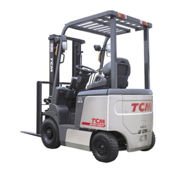
FORKLIFT TRUCK
TCM CORPORATION
No. SEB-81BBE
Counter Balanced
FB10
FB15
FB18
FB20
FB25
FB30
FB25
FB25
FB30
FB35
-7
-7
-7
-7
-7
-7
-7LB
-7V
-7V
-7S
Table of
Contents
Previous
Page
Next
Page
1
2
3
4
5
Advertisement
Table of Contents
Troubleshooting
MAINTENANCE
49
TROUBLESHOOTING GUIDE
90
TROUBLESHOOTING GUIDE
143
Need help?
Do you have a question about the FB10-7 and is the answer not in the manual?
Ask a question
Questions and answers
Related Manuals for TCM FB10-7
Forklifts TCM FB10-7 Operation & Maintenance Manual
Electric forklift truck counter-balanced type (135 pages)
Forklifts TCM FB-8 Series Service Manual
(259 pages)
Forklifts TCM FB18-7 Service Manual
Forklift truck (175 pages)
Forklifts TCM FB35-7S Service Manual
Forklift truck (175 pages)
Forklifts TCM FD35C9 Workshop Manual
Forklift truck (291 pages)
Forklifts TCM FG40T9 Workshop Manual
Forklift truck (291 pages)
Forklifts TCM FD35T9 Workshop Manual
Forklift truck (291 pages)
Forklifts TCM FD40T9 Workshop Manual
Forklift truck (291 pages)
Forklifts TCM FD45T9 Workshop Manual
Forklift truck (291 pages)
Forklifts TCM FD50T9 Workshop Manual
Forklift truck (291 pages)
This manual is also suitable for:
Fb15-7
Fb18-7
Fb20-7
Fb25-7
Fb30-7
Fb25-7lb
...
Show all
Fb25-7v
Fb30-7v
Fb35-7s
Table of Contents
Save PDF
Print
Rename the bookmark
Delete bookmark?
Delete from my manuals?
Login
Sign In
OR
Sign in with Facebook
Sign in with Google
Upload manual
Upload from disk
Upload from URL


Need help?
Do you have a question about the FB10-7 and is the answer not in the manual?
Questions and answers