Table of Contents
Advertisement
Quick Links
INSTRUCTION MANUAL
7064R-S-1844
18BIT DUAL ADC MODULE
PUBLICATION NO. 980817-S-1844
RACAL INSTRUMENTS
Racal Instruments, Inc.
Racal Systems Elettronica s.r.l.
4 Goodyear St., Irvine, CA 92618-2002
Strada 2-Palazzo C4, 20090 Milanofiori Assago, Milan, Italy
Tel: (800) RACAL-ATE, (800) 722-2528, (949) 859-8999;
Tel: +39 (0)2 5750 1796; FAX +39 (0)2 5750 1828
FAX: (949) 859-7139
Racal Elektronik System GmbH.
Racal Instruments, Ltd.
Technologiepark Bergisch Gladbach, Friedrich-Ebert-Strasse, D-51429
480 Bath Road, Slough, Berkshire, SL1 6BE, United Kingdom
Bergisch Gladbach, Germany
Tel: +44 (0) 1628 604455; FAX: +44 (0) 1628 662017
Tel.: +49 2204 8442 00; FAX: +49 2204 8442 19
Racal Systems Electronique S.A.
Racal Instruments, Ltd.
18 Avenue Dutartre, 78150 LeChesnay, France
Unit 5, 25F ., Mega Trade Center, No 1, Mei Wan Road, Tsuen Wan, Hong
Tel: +33 (1) 3923 2222; FAX: +33 (1) 3923 2225
Kong, PRC Tel: +852 2405 5500, FAX: +852 2416 4335
http://www.racalinstruments.com
PUBLICATION DATE: March 26, 2002
Copyright 2002 by Racal Instruments, Inc. Printed in the United States of America. All rights reserved.
This book or parts thereof may not be reproduced in any form without written permission of the publisher.
Advertisement
Table of Contents

Subscribe to Our Youtube Channel
Related Manuals for Racal Instruments 7064R-S-1844


Summary of Contents for Racal Instruments 7064R-S-1844
- Page 1 PUBLICATION DATE: March 26, 2002 Copyright 2002 by Racal Instruments, Inc. Printed in the United States of America. All rights reserved. This book or parts thereof may not be reproduced in any form without written permission of the publisher.
- Page 2 Authorization is required from Racal Instruments before you send us your product for service or calibration. Call your nearest Racal Instruments support facility. A list is located on the last page of this manual. If you are unsure where to call, contact Racal Instruments, Inc. Customer Support Department in Irvine, California, USA at...
- Page 3 FOR YOUR SAFETY Before undertaking any troubleshooting, maintenance or exploratory procedure, read carefully the WARNINGS and CAUTION notices. This equipment contains voltage hazardous to human life and safety, and is capable of inflicting personal injury. If this instrument is to be powered from the AC line (mains) through an autotransformer, ensure the common connector is connected to the neutral (earth pole) of the power supply.
- Page 4 This page was intentionally left blank.
-
Page 5: Table Of Contents
Chapter 2 INSTALLATION INSTRUCTIONS....................... 2-1 Introduction ............................. 2-1 Unpacking and Inspection ......................2-1 Address Switch Settings for Configuration Control................ 2-1 7064R-S-1844 to VXIbus Main Frame Installation................2-2 Power-up Initialization........................2-2 Configuration Defaults ........................2-3 Chapter 3 DRAWINGS............................3-1 Chapter 4 PARTS LIST............................ - Page 6 Instruction Manual 7064R-S-1844 List Of Figures Figure 1-1, 7064R-S-1844 Front Panel labeled 6088 ................ 1-1 Figure 1-2, 7064R-S-1844 Register-Based Module ................1-3 Figure 2-1, 7064R-S-1844 Logical Address Switch ................2-4 Figure 2-2, ID register Jumpers ......................2-5 Figure 2-3, Device Type Register Jumpers..................2-6 List Of Tables Table 1-1, Functional Performance ....................
-
Page 7: General Description
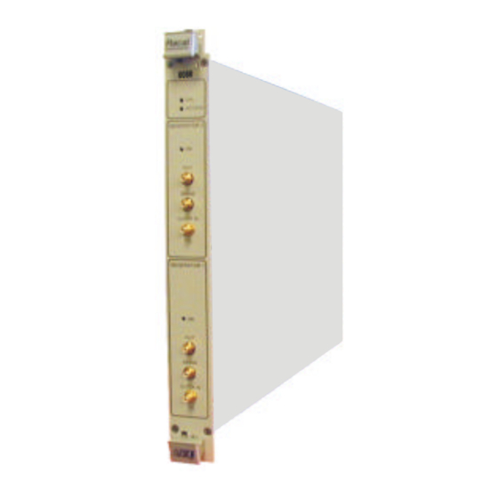
GENERAL DESCRIPTION This manual contains information on how to install and operate the Introduction 7064R-S-1844 in a VXIbus environment. It describes the function of the 7064R-S-1844 Register Based Dual 18 BIT DAC Module. Figure 1-1, 7064R-S-1844 Front Panel labeled 6088... -
Page 8: General Description
Instruction Manual 7064R-S-1844 The 7064R-S-1844 is a register based Dual 18 BIT 1MHz DAC VXI General Module. Description The 7064R-S-1844 interface logic maps the internal registers of the ADC modules to the VXI A24 Address space. All transfers to and from the ADC models are full 32 bit data transfers, although bits D31-D24 are not used. -
Page 9: Figure 1-2, 7064R-S-1844 Register-Based Module
Instruction Manual 7064R-S-1844 Address Switch Address Switch set to “0” set to “1” DAC Module 0 DAC Module 1 Figure 1-2, 7064R-S-1844 Register-Based Module General Description 1-3... -
Page 10: 7064R-S-1844 Specifications
Logical Addressing: Static 1-254, Switch Selectable Address Space: A16/A24 Data Transfer Bus: D32 support Device Class: Register Based Slave Device Interrupt Levels: None Table 1-2, 7064R-S-1844 Module Power Requirements Power Supply Specification 1.5A -5.2V +24V 325mA -24V 325mA -12V 225mA... -
Page 11: Table 1-3, Cooling Requirements
Specification Module Power 24 Watts Minimum Airflow 2.0 Liters/sec at approx .25mm H O for a 10 C Rise Table 1-4, 7064R-S-1844 Mechanical Parameters Parameter Specification Enclosure Style VXI"C" SIZE - Module Enclosure Enclosure Dimensions (in.) 14Lx 10.3W x l.2D Module Weight 3.2lbs. -
Page 12: Input/Output Definitions
Instruction Manual 7064R-S-1844 Unless otherwise specified all logic signals are TTL compatible; "-“, INPUT/OUTPUT designates an active low signal Definitions Notes: 1. Refer to VXIbus Rev 1.4 for details. Table 1-7, P1 / P2 Input / Output Descriptions I/O Signals... -
Page 13: Installation Instructions
If the shipping carton is Inspection damaged, inform the carrier immediately. 2. Remove the 7064R-S-1844 module and inspect it for damage. If any damage is apparent, inform the carrier immediately. Retain shipping carton and packing material for the carrier’s inspection. -
Page 14: 7064R-S-1844 To Vxibus Main Frame Installation
The 7064R-S-1844 Register Based module is ready for operation 7064R-S-1844 to when shipped. The address switch is set to 2. VXIbus Main To install the 7064R-S-1844 in a C-size VXI chassis, use the Frame Installation following instructions: 1. Ensure power is OFF. -
Page 15: Configuration Defaults
Instruction Manual 7064R-S-1844 the front panel – FAIL, ACCESS, MOD 0 ON, and MOD 1 ON. The LED functions are: FAIL• On during a (user provided) self-test Off when the (user provided) self-test has successfully completed ACCESS• Blinks on when the VXIbus is accessing the 7064R-S-1844 Module MOD 0 ON•... -
Page 16: Figure 2-1, 7064R-S-1844 Logical Address Switch
Instruction Manual 7064R-S-1844 S1 Logical Address Default = 02 (On = 1) Logical Address Figure 2-1, 7064R-S-1844 Logical Address Switch Installation Instructions 2-4... -
Page 17: Figure 2-2, Id Register Jumpers
Instruction Manual 7064R-S-1844 JP2 ID Register (Upper Half) Default = CF Device Class Memory Extended Message Based Register Based Address Space 0 A16 / A24 0 A16 / A32 Reserved 1 A16 Only Upper 4 Bits of Manufacturer’s ID JP1 ID Register (Lower Half) Default = FB Lower 8 Bits of Manufacturer’s ID... -
Page 18: Figure 2-3, Device Type Register Jumpers
Instruction Manual 7064R-S-1844 JP4 Device Type Register (Upper Half) Default = F7 Required Memory Model Code Upper 4 Bits JP3 Device Type Register (Lower Half) Default = FC Model Code Lower 8 Bits 1 2 3 4 5 6 7 8... -
Page 19: Drawings
Instruction Manual 7064R-S-1844 Chapter 3 DRAWINGS 407620-110S1844 Final Assy, 7064R-110S1844 ............3-3 405180 PCB Assy, S1843/S1844 ...............3-4 435180 Schematic, 7064R-S1843/1844 ............3-6 Wiring Diagram, 7064R-S1844 ..........3-20 Drawings 3-1... - Page 20 Instruction Manual 7064R-S-1844 This page was left intentionally blank. Drawings 3-2...
- Page 21 Instruction Manual 7064R-S-1844 Drawings 3-3...
- Page 22 Instruction Manual 7064R-S-1844 Drawings 3-4...
- Page 23 Instruction Manual 7064R-S-1844 Drawings 3-5...
- Page 24 Instruction Manual 7064R-S-1844 Drawings 3-6...
- Page 25 Instruction Manual 7064R-S-1844 Drawings 3-7...
- Page 26 Instruction Manual 7064R-S-1844 Drawings 3-8...
- Page 27 Instruction Manual 7064R-S-1844 Drawings 3-9...
- Page 28 Instruction Manual 7064R-S-1844 Drawings 3-10...
- Page 29 Instruction Manual 7064R-S-1844 Drawings 3-11...
- Page 30 Instruction Manual 7064R-S-1844 Drawings 3-12...
- Page 31 Instruction Manual 7064R-S-1844 Drawings 3-13...
- Page 32 Instruction Manual 7064R-S-1844 Drawings 3-14...
- Page 33 Instruction Manual 7064R-S-1844 Drawings 3-15...
- Page 34 Instruction Manual 7064R-S-1844 Drawings 3-16...
- Page 35 Instruction Manual 7064R-S-1844 Drawings 3-17...
- Page 36 Instruction Manual 7064R-S-1844 Drawings 3-18...
- Page 37 Instruction Manual 7064R-S-1844 Drawings 3-19...
- Page 38 Instruction Manual 7064R-S-1844 Drawings 3-20...
-
Page 39: Parts List
Instruction Manual 7064R-S-1844 Chapter 4 PARTS LIST 407620-110S1844 Final Assembly, 7064R-110S1844 405180 PCB Assy, S1843/1844 Parts List 4-1... - Page 40 Instruction Manual 7064R-S-1844 This page was left intentionally blank. Parts List 4-2...
- Page 41 Instruction Manual 7064R-S-1844 RACAL INSTRUMENTS INC. PAGE 1 Product Structure Report 3/25/02 By Assembly/Balloon No. Assembly: 407620-110S1844 7064R-110-S-1844,DUAL DAC Rev Date: 3/25/02 Revision: B Component Description Oty Reqd Engineer Txt SP-152-CA 1260 CARD PAK 1.00000 405180 PCB ASSY,7064R-S-1843/1844 1.00000 455781 PANEL, REAR, SINGLE 1.00000...
- Page 42 Instruction Manual 7064R-S-1844 RACAL INSTRUMENTS INC. PAGE 1 Product Structure Report By Assembly/Balloon No. Assembly: 405180 EA PCB ASSY 7064R-S-1843/1844 Rev Date: 3/21/02 Revision: A Component Description Qty Reqd Engineer Txt 050000-000 RSCH1-000. 00H . 06W005 1.00000 R115 050000-471 RSCB1-470. 00H.06W005 48.00000...
- Page 43 Instruction Manual 7064R-S-1844 310193 CKPL-SH005. 00U10. 1%I 1.00000 415180 POE, 7064R-S-1843/1844 1.00000 456979 SPACER, DIN CONN MTG 2.00000 Parts List 4-5...
- Page 44 Instruction Manual 7064R-S-1844 RACAL INSTRUMENTS INC. PAGE 2 Product Structure Report By Assembly/Balloon No. Assembly: 405180 EA PCB ASSY 7064R-S-1843/1844 Rev Date: 3/21/02 Revision: A Component Description Qty Reqd Engineer Txt 601197 POST-TEST- .025 SQ 2.00000 TP1 , TP2 601208-010 CON-PCB-PLG02SD.
- Page 45 Instruction Manual 7064R-S-1844 This page was left intentionally blank. Parts List 4-7...
-
Page 47: Chapter 5 Product Support
Instruction Manual 7064R-S-1844 Chapter 5 PRODUCT SUPPORT Racal Instruments has a complete Service and Parts Department. Product Support If you need technical assistance or should it be necessary to return your product for repair or calibration, call 1-800-722-3262 or 949-859-8999 and ask for Customer Support. You may also contact Customer Support via E-Mail at: helpdesk@racalate.com... - Page 48 Instruction Manual 7064R-S-1844 Racal Instruments, Inc. Support Offices 4 Goodyear St., Irvine, CA 92618-2002 Tel: (800) RACAL-ATE, (800) 722-2528, (949) 859-8999; FAX: (949) 859-7139 Racal Instruments, Ltd. 480 Bath Road, Slough, Berkshire, SL1 6BE, United Kingdom Tel: +44 (0) 1628 604455; FAX: +44 (0) 1628 662017 Racal Systems Electronique S.A.
Need help?
Do you have a question about the 7064R-S-1844 and is the answer not in the manual?
Questions and answers