Table of Contents
Advertisement
Advertisement
Table of Contents

Subscribe to Our Youtube Channel
Related Manuals for Racal Instruments 2460 Series


Summary of Contents for Racal Instruments 2460 Series
- Page 1 Artisan Technology Group is your source for quality new and certified-used/pre-owned equipment SERVICE CENTER REPAIRS WE BUY USED EQUIPMENT • FAST SHIPPING AND DELIVERY Experienced engineers and technicians on staff Sell your excess, underutilized, and idle used equipment at our full-service, in-house repair center We also offer credit for buy-backs and trade-ins •...
- Page 2 PUBLICATION DATE: June 23, 2003 Copyright 1999 by Racal Instruments Printed in the United Kingdom. All rights reserved. This book or parts thereof may not be reproduced in any form without written permission of the publisher. Artisan Technology Group - Quality Instrumentation ... Guaranteed | (888) 88-SOURCE | www.artisantg.com...
- Page 3 Authorization is required from Racal Instruments before you send us your product for service or calibration. Call your nearest Racal Instruments support facility. A list is located on the last page of this manual. If you are unsure where to call, contact Racal Instruments, Inc. Customer Support Department in Irvine, California, USA at 1-800-722-3262 or 1-949-859-8999 or via fax at 1-949-859-7139.
- Page 4 This document and the technical data herein disclosed, are proprietary to Racal Instruments, and shall not, without express written permission of Racal Instruments, be used, in whole or in part to solicit quotations from a competitive source or used for manufacture by anyone other than Racal Instruments. The information herein...
- Page 5 Artisan Technology Group - Quality Instrumentation ... Guaranteed | (888) 88-SOURCE | www.artisantg.com...
-
Page 6: Safety Precautions
SAFETY PRECAUTIONS SYMBOLS AND HEADINGS The following symbols and headings are used in this handbook to indicate Safety hazards. Personnel using this equipment must read this handbook and familiarize themselves with each safety requirement before operating the equipment. WARNING: A WARNING indicates a hazard that affects personnel. The instructions in a WARNING must be observed;... - Page 7 the mains supply in the event of a hazard arising. The switch circuit breaker should be clearly marked as the disconnecting device. 5. The environmental operating conditions specified for the instrument must be observed. Do not allow the instrument to become wet, and do not allow water to enter the instrument. Do not operate the instrument when wet because in this condition the safety of the instrument may be degraded.
-
Page 8: Table Of Contents
User Manual 2460 Series Table of Contents Chapter 1 GENERAL ...........................1-1 Model 2460 Series VXIbus Module ..................1-1 Modularity and Flexibility ......................1-2 Cost Effective...........................1-2 Field Upgradable........................1-2 Chapter 2 INSTALLATION INSTRUCTIONS ....................2-1 Unpacking and Inspection ......................2-1 Reshipment Instructions......................2-1 INSTALLATION ........................2-2 Installing the VXIplug&play Driver..................2-4 Recommended Controllers.......................2-4... - Page 9 User Manual 2460 Series List of General SCPI Commands..................4-6 INSTrument Subsystem....................4-7 STATus subsystem......................4-9 SYSTem subsystem ....................... 4-14 Common commands......................4-17 Error Messages ........................4-26 No Errors..........................4-26 Command Errors ........................ 4-26 Execution Errors......................... 4-28 Instrument-Specific Errors ....................4-29 VXIbus Word Serial commands ..................... 4-30 Abort Normal Operation......................
- Page 10 Figure 1-1, The 2460 Series VXIbus Module ................1-1 Figure 1-2, The 2460 VXIbus Module ..................1-2 Figure 2-1, The installation of the 2460 Series VXIbus Module............2-2 Figure 2-2, Location of S1 ......................2-3 Figure 3-1, Main Soft Front Panel of the 2461 application ............3-2 Figure 3-2, ‘System Functions’...
- Page 11 User Manual 2460 Series This page was left intentionally blank. Artisan Technology Group - Quality Instrumentation ... Guaranteed | (888) 88-SOURCE | www.artisantg.com...
-
Page 12: Chapter 1 General
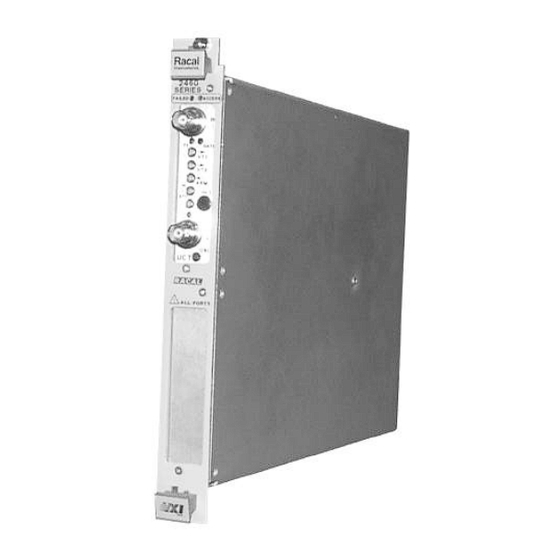
User Manual 2460 Series Chapter 1 GENERAL The 2460 series is based on an innovative module produced by Model 2460 Series RACAL Instruments. It’s design was developed to reduce the VXIbus Module size and cost of test systems by allowing more than one function in a single VXIbus module. -
Page 13: Modularity And Flexibility
User Manual 2460 Series Figure 1-2, The 2460 VXIbus Module The 2460 Series VXIbus Module will allow up to 3 separate Modularity and function cards to be fitted in a single “C” size slot. Slot or positions Flexibility 1 and 2 provide access to the front panel, while slot/position 3 allows for future development or enhancements. -
Page 14: Installation Instructions
User Manual 2460 Series Chapter 2 INSTALLATION INSTRUCTIONS 1. Before unpacking the 2460 Series module, check the Unpacking and exterior of the shipping carton for any signs of damage. All Inspection irregularities should be noted on the shipping bill. 2. Remove the instrument from its carton, preserving the factory packaging as much as possible. -
Page 15: Installation
User Manual 2460 Series The installation of the 2460 Series VXIbus module into a chassis INSTALLATION or mainframe is shown in the following diagram: Figure 2-1, The installation of the 2460 Series VXIbus Module Before commencing installation of the 2460 Series VXI Module instrument, carry out a visual inspection of it. -
Page 16: Figure 2-2, Location Of S1
User Manual 2460 Series Figure 2-2, Location of S1 To install the 2460 Series VXI Module in a C size VXI mainframe, ensure that the it has the rear connector P1 oriented to mate with the corresponding connector on the mainframe backplane. Align the module with the guides for the slot selected, and slide the module into the mainframe. -
Page 17: Recommended Controllers
Driver and computer must be running WIN 95 or WIN NT. Product Manuals NOTE: This CD also contains the 2460 Series manual part number 980833 and the 2461C Universal Counter Timer manual 980833-002. Power-up the chassis/mainframe. Ensure that the SYSFAIL LED Checking To See on the module’s front panel illuminates and then extinguishes... -
Page 18: Chapter 3 Vxiplug&Play Driver
User Manual 2460 Series Chapter 3 OPERATION OF THE 2461 VIA THE VXIplug&play DRIVER Use of the VXIplug&play driver allows the operator to develop VXIplug&play programs without intimate knowledge of the command set, SCPI Driver or IEEE 488.2 standards. The driver consists of a number of functions, help files, soft front panels, knowledge base and help facility. -
Page 19: Figure 3-1, Main Soft Front Panel Of The 2461 Application
User Manual 2460 Series If it is desired to run the demonstration version then the ‘YES’ option should be selected. If one 2461 is found then the main front panel of the 2461 will appear on the screen and appear similar to that shown in Figure 3-1. -
Page 20: Figure 3-2, 'System Functions' Secondary Panel Of The 2461 Application
User Manual 2460 Series The Hide All FC Panels button temporarily disables the active secondary panels. The About button, shown in Figure 3-3, contains information on the instrument driver and firmware of the 2461 and function cards. The Help button supports on-line help which provides the user with an efficient way to use the panel without referring to printed documentation. -
Page 21: Figure 3-3, Status
User Manual 2460 Series SCPI version to which the instrument conforms. The System Error displays Error Number. It specifies the error code of the most recent Error Message generated by the 2461. If more than one error is present in the queue a Next control may be operated successively until no more errors are available. -
Page 22: Figure 3-3, 'About' Secondary Soft Front Panel Of The 2461 Application
User Manual 2460 Series Figure 3-3, ‘About’ secondary Soft Front Panel of the 2461 application This panel shows the Software revision of the soft front panel, instrument driver, VISA library and LabWindows/CVI. As well as instrument details such as, its type and serial number, the SCPI revision to which the software complies, the firmware revision of the main board and any function card(s). - Page 23 User Manual 2460 Series This page was left intentionally blank. Racal Instruments © 2003 Using The 2461 Module 3-6 Artisan Technology Group - Quality Instrumentation ... Guaranteed | (888) 88-SOURCE | www.artisantg.com...
-
Page 24: Programming The 2461 Module
User Manual 2460 Series Chapter 4 PROGRAMMING THE 2461 MODULE This Section provides information about using the general Introduction SCPI commands, and how to establish the correct system configurations for the VXI application function cards mounted in the 2461 VXI Module. -
Page 25: Operation Via The Scpi Command Set
User Manual 2460 Series A brief description of the SCPI syntax is provided to allow Operation Via The basic operation. For a more detailed definition of SCPI the SCPI Command Set appropriate specification should be consulted. SCPI, in conjunction with IEEE 488.2, lays down rules for SCPI Principles syntax and protocols for instrument control. - Page 26 User Manual 2460 Series Command Command mnemonic mnemonic DATA DATA Space Commands may be concatenated on the same line: Command Command Racal Instruments © 2003 Programming The 2461 Module 4-3 Artisan Technology Group - Quality Instrumentation ... Guaranteed | (888) 88-SOURCE | www.artisantg.com...
-
Page 27: Sending And Receiving Scpi Commands Over The Vxibus
User Manual 2460 Series Commands and string data in SCPI have two forms, long form and short form, in the following command definitions and examples capitals are used to represent the short form and a mix of capitals and lowercase make up the long form. The 2461 can only accept the long or the short form as defined. -
Page 28: Status And Error Reporting
User Manual 2460 Series Status and error reporting commands fall within the general Status and Error command set so these can be accessed at any time. Status, Reporting and set up of the status system, is done by the STATUS subsystem while error messages are retrieved by the SYSTem:ERRor? Command. -
Page 29: General Commands
User Manual 2460 Series General Commands List of General SCPI Commands INSTrument command summary Command Description :INSTrument :CATalog? Lists the present instruments :SELect Selects an instrument by name :SELect? Returns the name of the currently selected instrument STATus command summary... -
Page 30: Instrument Subsystem
User Manual 2460 Series INSTrument Subsystem The INSTrument subsystem provides a mechanism to identify and select the different instruments present on the VXI module. INSTrument command summary Command Description :INSTrument :CATalog? Lists the present instruments :SELect Selects an instrument by name... - Page 31 User Manual 2460 Series Model list of identifiers One function card COUNter1 Two function cards COUNter1 or COUNter2 The identifier list can be retrieved by the "INSTrument:CATalog?" command. Initialization: *RST COUNTer1 Example: "INST:SEL COUNter1" Selects the COUNter1 instrument "MEAS:FREQ?" Takes a frequency measurement (COUNTer1) "INST:CAT?
-
Page 32: Status Subsystem
User Manual 2460 Series STATus subsystem STATus command summary Command Description :STATus Path to control operation registers: :OPERation [:EVENt]? Reads the event register :ENABle Programs the enable register :ENABle? Reads the enable register :CONDition? Reads the condition register :PRESet Returns status registers to default... -
Page 33: Figure 4-1, Operation Status Register
User Manual 2460 Series Operation MEAS MEAS TEST ------- ------- ------- INIT INIT ------- ------- ------- ------- ------- ------- ------- ------- Condition Register Operation ------- ------- ------- INIT MEAS INIT TEST ------- ------- ------- ------- ------- ------- ------- ------- MEAS... - Page 34 User Manual 2460 Series STATus:PRESet Description: Clears to zero all bits of the Status Operation Enable Register. Clears to zero all bits of the Status Operation Condition Register. This command does not erase the EVENt registers. ********************************************** STATus:OPERation[:EVENt]? ==> <numeric_value>...
- Page 35 User Manual 2460 Series The sum of the decimal weights of the bits that you wish to set is sent as the parameter ( <numeric_value> ) for the appropriate :ENABle: command. Initialization: *RST, *CLS Not affected Power-up: Note that after power-up, by default, none of the bits of the STATus:OPERation:EVENt register are reported to bit 7 of the Status Byte.
- Page 36 User Manual 2460 Series Bit B11, Initiate state (Init2): Set when the second instrument is in the Initiate state (Trigger mode) and clear when it returns in the idle state (normal mode). Bit B12, Data available (Meas2): Set when all of the required measurements have been completed by instrument 2.
-
Page 37: System Subsystem
User Manual 2460 Series SYSTem subsystem SYSTem command summary Command Description :SYSTem :PRESet Sets the device to the default state. :VERSion? Returns the SCPI year-version. :ERRor? Queries the Error Queue. :TIMeout Sets a time-out period :TIMeout? Returns the time-out period... - Page 38 User Manual 2460 Series occurs after the queue is already full, the message "350, Queue overflow" is stored instead of the error. Any further errors are not stored. ********************************************** SYSTem:TIMeout <integer> Description: Sets the maximum amount of time a query measurement command (FETCh?, READ?, MEAS?) is allowed to take.
- Page 39 User Manual 2460 Series <Only 2 of the 5 measurements are armed and completed> <+00003.9862505E+00, +00003.9862505E+00,+9.90000000000E+37, +9.90000000000E+37, +9.90000000000E+37> Interrogative form: SYSTem:TIMeout?: <integer> Queries the programmed time-out. Racal Instruments © 2003 Programming The 2461 Module 4-16 Artisan Technology Group - Quality Instrumentation ... Guaranteed | (888) 88-SOURCE | www.artisantg.com...
-
Page 40: Common Commands
User Manual 2460 Series Common commands IEEE 488.2 common command summary: Command Description *CLS Clears all Event register and Error queue. *ESE Sets the contents of the Standard Event Enable Register. *ESE? Request the programmed value of the Standard Event Enable Register. -
Page 41: Figure 4-2 : Status Byte And Service Request
User Manual 2460 Series Status Summary Messages Status Service Byte *STB? (B6) Request (B7) (B5) (B4) (B3) (B2) (B1) (B0) Register Generation & & & & *SRE (B7) (B6) (B5) (B4) (B3) (B2) (B1) (B0) *SRE? Service Request Enable Register... -
Page 42: Figure 4-3 : Standard Event Status
User Manual 2460 Series Standard Event Status Register *ESR *ESR? (B7) (B6) (B5) (B4) (B3) (B2) (B1) (B0) & & & & & To Event Summary Bit (ESB) *ESE of the Status Byte *ESE? Register (B7) (B6) (B5) (B4) (B3) - Page 43 User Manual 2460 Series *CLS Description: Erases all the Event registers, all Condition registers, the Error Queue and the Status Byte Register. ********************************************** *ESE <numeric_value> Description: Sets the Standard Event Enable Register. This command is sent with the decimal equivalent of the binary value that determines the desired state (0 or 1) of the bits in the register.
- Page 44 User Manual 2460 Series where CME (bit B5) = Decimal QYE (bit B2) = Decimal parameter Initialization: Power-up Clears register *CLS No effect *RST No effect STATus:PRESet No effect ********************************************** *ESE? ==> <numeric_value> Description: Returns the programmed value of the Standard Event Enable Register.
- Page 45 User Manual 2460 Series Initialization: Power-up Clears register *CLS Clears register *RST No effect STATus:PRESet No effect ********************************************** *IDN? ==> RACAL,<Model_number>,<Serial_Number>,<Firmware_revision> [-<FunctionCard1 Firmware_revision >[-<FunctionCard2 Firmware_revision>]] Description: Returns the model identification: manufacturer, model number, serial number and firmware revision(s). For example: RACAL,2461,U971301,01.03-01.03-01.03...
- Page 46 User Manual 2460 Series *OPC? ==> 1 Description: When this common command is sent, an ASCII ‘1’ will be placed in the VXI Output buffer after the last pending operation is completed. The ‘1’ in the Output buffer will set the MAV (Message Available) bit (B4) of the Status Byte Register.
- Page 47 User Manual 2460 Series Set OSB bit (B7) The sum of the decimal weight of the bits that you which to set is the value that is sent with the *SRE command. For example, to set the ESB and MAV bits of the SRE...
- Page 48 User Manual 2460 Series *TST? ==> <result> Description: Execute a self-test on the module and returns the result. This command connects the standard frequency in use to the counting input and takes frequency measurements. Both UCT boards are tested. The test fails if the frequency measurement differs from 10MHz.
-
Page 49: Error Messages
User Manual 2460 Series Error Messages No Errors Error Description [Description/Explanation/Examples] Number 0 No Errors [The queue is empty. Each error/event in the queue has been read or the queue was erased by power on]. Command Errors Error Description [Description/Explanation/Examples]... - Page 50 User Manual 2460 Series -109 Missing Parameter [The number of parameters is less than required. For example, the *SRE command requires a parameter, so the command *SRE is illegal.] -112 Command Mnemonic Too Long [The command mnemonic contains at most twelve characters (see IEEE 488.2, 7.6.1.4.1).]...
-
Page 51: Execution Errors
User Manual 2460 Series Execution Errors Error Description [Description/Explanation/Examples] Number -200 Execution Error [This error occurs when the VXI output buffer is full, or if the INTERRUPT QUEUE is full, or if the calibration date has been forgotten when closing the calibration process.]... -
Page 52: Instrument-Specific Errors
User Manual 2460 Series -230 Data Corrupt or Stale [A FETCh? command is sent but no data is available while the device is in idle state.] -240 Hardware Error [A command or request may not be executed because it is not allowed. For example, no instrument is selected and the user sends a MEASure command.]... -
Page 53: Vxibus Word Serial Commands
User Manual 2460 Series VXIbus Word Serial commands The 2400 VXI Instrumentation module supports the following commands. They are described in detail in the following paragraphs. Abort Normal Operation Assign Interrupt Line Asynchronous Mode Control Begin Normal Operation Byte Available... -
Page 54: Assign Interrupt Line
User Manual 2460 Series Assign Interrupt Line This command is used to assign an IRQ line of the VME bus to a slave interrupt generator. Command: Int_ID Line Insignificant Int_ID: Unique identifier of the assigned interrupt generator. For this model, the 'INT_ID' field has the value '001'. -
Page 55: Asynchronous Control Mode
User Manual 2460 Series Asynchronous Control Mode A ‘master’ uses this command to create a path for events and responses. Command: 15 14 Resp Event Resp* Event* Mode Mode Insignificant Val Resp*: A zero (0) enables reply generation. A one (1) disables reply generation. -
Page 56: Begin Normal Operation
User Manual 2460 Series Begin Normal Operation This command tells the instrument it can execute a normal operational cycle. Command: FCFF or FDFE The response is placed in the Data Low Register. Response: FFFE Byte Available A ‘master’ uses this command to send a byte of data to the ‘slave’. The END field indicates the last byte of the message. -
Page 57: Byte Request
User Manual 2460 Series Byte Request The ‘master’ uses this command to receive a data byte from a ‘slave’ instrument. Command: AEFF The response is placed in the Data Low Register. The END field indicates the last byte of the message. -
Page 58: Control Event
User Manual 2460 Series Control Event This command is used by a ‘master’ to selectively enable events generated by the ‘slave’. A one (1) in the validation field enables specific event generation. A zero (0) in the validation field disables specific event generation. -
Page 59: Read Interrupt Line
User Manual 2460 Series Read Interrupt Line This command is used to determine to which of the VME bus IRQ lines a slave's particular interrupt generator is connected. Command: Int_ID Insignificant Int_ID: Unique identifier of the specific interrupt generator. For this module the 'Int_ID' field must contain the value '001'. -
Page 60: Read Protocol
User Manual 2460 Series Read Protocol A ‘master’ uses this command to determine what protocol is used in the word serial protocol used by the ‘slave’. Command: DFFF The supported protocol word is placed in the Data Low Register. Response:... -
Page 61: Read Protocol Error
User Manual 2460 Series Read Protocol Error A ‘master’ uses this command to ask its ‘slave’ to report its current error status in the form of a 16- bit response. After having replied to this command, the ‘slave’ resets its Current Error status to ‘No Error’. -
Page 62: Read Stb
User Manual 2460 Series Read STB This command allows a ‘master’ to read the status byte of a ‘slave’. Command: CFFF The status byte is placed in the Data Low Register. Response: Status Byte Racal Instruments © 2003 Programming The 2461 Module 4-39... - Page 63 User Manual 2460 Series This page was left intentionally blank. Racal Instruments © 2003 Programming The 2461 Module 4-40 Artisan Technology Group - Quality Instrumentation ... Guaranteed | (888) 88-SOURCE | www.artisantg.com...
- Page 64 Artisan Technology Group is your source for quality new and certified-used/pre-owned equipment SERVICE CENTER REPAIRS WE BUY USED EQUIPMENT • FAST SHIPPING AND DELIVERY Experienced engineers and technicians on staff Sell your excess, underutilized, and idle used equipment at our full-service, in-house repair center We also offer credit for buy-backs and trade-ins •...
Need help?
Do you have a question about the 2460 Series and is the answer not in the manual?
Questions and answers