
Related Manuals for NEC IE-V850ES-G1


Summary of Contents for NEC IE-V850ES-G1
- Page 1 User’s Manual IE-V850ES-G1 In-Circuit Emulator Target Device V850ES Document No. U16313EJ1V0UM00 (1st edition) Date Published March 2003 N CP(K) © Printed in Japan...
- Page 2 [MEMO] User’s Manual U16313EJ1V0UM...
- Page 3 V850ES/SA2, V850ES/SA3, V850ES/KF1, V850ES/KG1, and V850ES/KJ1 are trademarks of NEC Electronics Corporation. Windows is either a trademark or a registered trademark of Microsoft Corporation in the United States and/or other countries. PC/AT is a trademark of International Business Machines Corporation.
- Page 4 NEC Electronics does not assume any liability for infringement of patents, copyrights or other intellectual property rights of third parties by or arising from the use of NEC Electronics products listed in this document or any other liability arising from the use of such products. No license, express, implied or otherwise, is granted under any patents, copyrights or other intellectual property rights of NEC Electronics or others.
- Page 5 Regional Information Some information contained in this document may vary from country to country. Before using any NEC Electronics product in your application, pIease contact the NEC Electronics office in your country to obtain a list of authorized representatives and distributors. They will verify: •...
- Page 6 To learn about the basic specifications and operation →Read this manual in the order listed in the CONTENTS. To learn the operation methods, command functions, etc., of the IE-V850ES-G1 →Read the user’s manual of the debugger (sold separately) that is used.
- Page 7 However, preliminary versions are not marked as such. Documents Related to Development Tools (User’s Manuals) Document Name Document Number IE-V850ES-G1 (In-Circuit Emulator for V850ES) This manual IE-703204-G1-EM1 (In-Circuit Emulator Option Board for V850ES/SA2 , V850ES/SA3 To be prepared...
-
Page 8: Table Of Contents
1.7.1 When using the emulator on a stand-alone basis for performing software debugging ......19 1.7.2 When performing hardware debugging with target system..............20 CHAPTER 2 PART NAMES AND FUNCTIONS................... 21 Part Names and Functions of IE-V850ES-G1................21 Clock Settings ..........................24 CPU Operating Voltage Range....................24 Cover Open/Close Procedure .................... - Page 9 Accessories..............................18 Part Names and Functions of IE-V850ES-G1 on Front Side................21 TRGOUT Signal Connector..........................22 Part Names and Functions of IE-V850ES-G1 on Back Side ................23 Part Names and Functions of Board .......................24 Cover Open/Close Procedure 1 (Removing Front Cover 1)................25 Cover Open/Close Procedure 1 (After Front Cover 1 Is Removed) ..............26 Cover Open/Close Procedure 2 (Loosening Screws) ..................27...
- Page 10 LIST OF TABLES Figure No. Title Page Pins of External Logic Probe Connector......................34 Electrical Characteristics of External Logic Probe Connector .................34 Factory Settings of Switches ...........................39 User’s Manual U16313EJ1V0UM...
-
Page 11: Chapter 1 Overview
CHAPTER 1 OVERVIEW The IE-V850ES-G1 is an in-circuit emulator that efficiently debugs hardware and software during the development of systems that employ V850ES microcontrollers. This in-circuit emulator incorporates functions such as a break/trace function using events, a coverage function for program performance evaluation, and a timer/counter function. -
Page 12: Hardware Configuration
CHAPTER 1 OVERVIEW 1.1 Hardware Configuration In-circuit emulator (IE-V850ES-G1) Separately sold hardware Emulation board The IE-V850ES-G1 can be used as an in-circuit (IE-70xxxx-G1-EM1) emulator of each V850ES device by connecting this board. A probe cable is supplied with the board (except some emulation boards). -
Page 13: Features
CHAPTER 1 OVERVIEW 1.2 Features Maximum operating frequency: 20 MHz A configuration that provides the highest possible equivalence with the target device is realized by omitting buffers between signal lines. The following pins can be masked (although these differ depending on the emulation board to be used). RESET, NMI, WAIT, HLDRQ The dimensions and environmental conditions for operation are as follows. -
Page 14: Function Specifications
CHAPTER 1 OVERVIEW 1.3 Function Specifications Item Specification Emulation memory capacity Internal ROM 1 MB External memory 4 MB Execution/pass detection coverage Internal ROM 1 MB memory capacity External memory In ROMless mode 2 MB When using iROM 1 MB 168 bits ×... -
Page 15: Hardware Configuration
CHAPTER 1 OVERVIEW 1.4 Hardware Configuration The basic hardware configuration of the IE-V850ES-G1 is as follows. Figure 1-1. Basic Hardware Configuration V850ES in-circuit emulator IE-V850ES-G1 (emulator main unit) Trace memory iROM memory Coverage memory Emulation CPU Host machine Emulation memory... -
Page 16: System Configuration
CHAPTER 1 OVERVIEW 1.5 System Configuration The system configuration when connecting the emulation board to the IE-V850ES-G1, which is then connected to a personal computer (PC-9800 series, PC/AT or compatibles) is illustrated below. Figure 1-2. System Configuration <7> <10> [Magnified drawing: example of use of connector for target connection] <6>... -
Page 17: Contents In Carton
CHAPTER 1 OVERVIEW 1.6 Contents in Carton The carton of the IE-V850ES-G1 contains a main unit, guarantee card, packing list, and accessory bag. Make sure that the accessory bag includes this manual and cables. In case of missing or damaged contents, please contact an NEC Electronics sales representative or an NEC Electronics distributor. - Page 18 CHAPTER 1 OVERVIEW Check that the accessory bag contains this manual, an accessory list, and the following accessories. (a) PC interface cable (for PCI bus, for PCMCIA): × 1 each 3 types, × 1 each (b) Power cable: × 1 (c) External logic probe: (d) External logic clips: 1 set (10 clips)
-
Page 19: Setup
CHAPTER 1 OVERVIEW 1.7 Setup The following two system configurations for the IE-V850ES-G1 are possible, depending on the purpose. This section describes the setup procedure according to each purpose as follows. Step Reference section 1.7.1 When using the emulator on a stand-alone basis for performing software debugging Connect interface board to PC 3.1 Connection to Personal Computer... -
Page 20: When Performing Hardware Debugging With Target System
Before turning on the power of the target system, make sure that the power of the IE-V850ES- G1 is turned on. If the target system is turned on while the IE-V850ES-G1 is off, the target system or the IE-V850ES-G1 may be damaged. -
Page 21: Chapter 2 Part Names And Functions
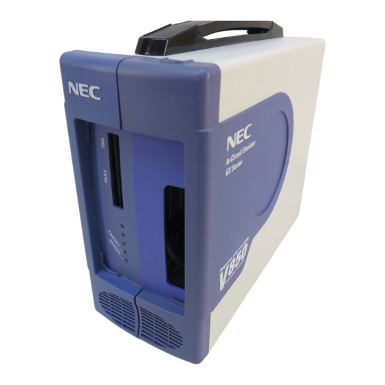
CHAPTER 2 PART NAMES AND FUNCTIONS This chapter describes the name and function of each part of the IE-V850ES-G1, as well as switch settings. 2.1 Part Names and Functions of IE-V850ES-G1 Figure 2-1 Part Names and Functions of IE-V850ES-G1 on Front Side... - Page 22 CHAPTER 2 PART NAMES AND FUNCTIONS (2) External logic probe connector Connect the external logic probe (included) to this connector. (3) TRGOUT signal connector This connector comprises the TRGOUT signal output and GND pins. Figure 2-2. TRGOUT Signal Connector GND pin TRGOUT signal output pin (open-drain output, 5 V tolerant) User’s Manual U16313EJ1V0UM...
- Page 23 CHAPTER 2 PART NAMES AND FUNCTIONS Figure 2-3. Part Names and Functions of IE-V850ES-G1 on Back Side Connector for PC interface Power switch Power cable jack Fuse holder Reset switch (1) Power switch This is the main power supply switch of the emulator.
-
Page 24: Clock Settings
(1) Jumpers (JP3 to JP7) Jumper setting is not required. Do not change the factory settings. If the user’s manual of the emulation board describes the setting of JP3 to JP7 of the IE-V850ES-G1, follow the setting described in the manual. -
Page 25: Cover Open/Close Procedure
CHAPTER 2 PART NAMES AND FUNCTIONS 2.4 Cover Open/Close Procedure 2.4.1 Removing probe and replacing clock module <1> Place your fingers at the positions indicated by the arrows below and pull front cover 1. Figure 2-5. Cover Open/Close Procedure 1 (Removing Front Cover 1) Front cover 1 User’s Manual U16313EJ1V0UM... - Page 26 CHAPTER 2 PART NAMES AND FUNCTIONS <2> Remove the probe or change the clock in the status shown below. Figure 2-6. Cover Open/Close Procedure 1 (After Front Cover 1 Is Removed) Front cover 1 User’s Manual U16313EJ1V0UM...
-
Page 27: Replacing Board
CHAPTER 2 PART NAMES AND FUNCTIONS 2.4.2 Replacing board <1> Remove front cover 1 following the procedures described in 2.4.1 Removing probe and replacing clock module. <2> Loosen the two screws indicated by the arrows below. Figure 2-7. Cover Open/Close Procedure 2 (Loosening Screws) User’s Manual U16313EJ1V0UM... - Page 28 CHAPTER 2 PART NAMES AND FUNCTIONS <3> Grip and pull up front cover 2 with the hinge installed on the rear panel as the center, and rotate the casing main unit as shown. Figure 2-8. Cover Open/Close Procedure 2 (Pulling up Front Cover 2) Front cover 2 User’s Manual U16313EJ1V0UM...
-
Page 29: Closing Cover
CHAPTER 2 PART NAMES AND FUNCTIONS <4> Remove the six screws on the board indicated by the arrows and replace the board. For replacement of the emulation board, refer to the user’s manual of each emulation board. Figure 2-9. Cover Open/Close Procedure 2 (After Front Cover Is Pulled up) 2.4.3 Closing cover Close the cover in the reverse procedure as that used when opening the cover. -
Page 30: Chapter 3 Connection Of Components
For the details on software startup, refer to the user’s manual of the debugger that is used. 3.1 Connection to Personal Computer 3.1.1 Overview of connection The IE-V850ES-G1 can use a personal computer (PC-9800 series, or PC/AT compatible) as the host machine. The connection to each type of personal computer is described below. (1) Desktop PC When using a desktop PC, insert the following PC interface board in the external expansion slot of the desktop PC and connect the computer to the IE-V850ES-G1. -
Page 31: Insertion Of Pc Interface Board
CHAPTER 3 CONNECTION OF COMPONENTS 3.1.3 Insertion of PC interface board The following describes the settings and connection of an IBM PC/AT (including its compatibles) and the IE- 70000-PCI-IF-A. Figures 3-1 and 3-2 show how to mount the PC interface board. <1>... -
Page 32: Connection Of Pc Interface Cable
3.1.4 Connection of PC interface cable Figure 3-3 shows how to connect the PC interface cable. Connect the PC interface cable (for PCI bus) supplied with the IE-V850ES-G1 to the PC interface connector of the PC interface board. Figure 3-3. Connection of PC Interface Board and PC Interface Cable... -
Page 33: Connection To Target System
CHAPTER 3 CONNECTION OF COMPONENTS 3.2 Connection to Target System For how to connect the IE-V850ES-G1 and target system, refer to the user’s manual of the emulation board. 3.3 Connection of External Logic Probe When using the external logic probe, connect it to the external logic probe connector of the IE-V850ES-G1. - Page 34 CHAPTER 3 CONNECTION OF COMPONENTS Figure 3-5. External Logic Probe Connector Pins <1> · · · · · · <10> Table 3-1. Pins of External Logic Probe Connector Pin No. <1> <2> <3> <4> <5> <6> <7> <8> <9> <10> Description Bit 0 Bit 1...
-
Page 35: Cable Connections
3.4 Cable Connections 3.4.1 Connection of power supply cable Connect the connector of the power supply cable (included) to the power supply cable jack on the main unit of the IE-V850ES-G1. Figure 3-6. Connection of Power Supply Cable Power switch... -
Page 36: Pc Interface Cable Connection
CHAPTER 3 CONNECTION OF COMPONENTS 3.4.2 PC interface cable connection Connect the PC interface cable to the PC interface connector of the IE-V850ES-G1. Figure 3-7. PC Interface Cable Connection PC interface connector PC interface cable (included) User’s Manual U16313EJ1V0UM... -
Page 37: External Logic Probe Connection
For details, refer to the emulation board user’s manual. 3.4.4 Additional information The IE-V850ES-G1 can perform real-time tracing of the emulation CPU bus cycle. For details of this function, refer to the debugger user’s manual. (1) Any eight signals can be traced in real-time. -
Page 38: System Power-On And Power-Off
(1) Turn on the power switch of the PC. (2) Turn on the power switch of the IE-V850ES-G1. Set the power switch to “ON” after connecting the power cable to the power jack of the IE-V850ES-G1 and the plug to the power outlet. -
Page 39: Chapter 4 Factory Settings
CHAPTER 4 FACTORY SETTINGS This chapter describes the switch settings when the product is shipped. 4.1 Factory Settings Table 4-1. Factory Settings of Switches Setting Description Power switch Power off Jumper (JP3) Shorted Leave the setting. Jumper (JP4) Open Leave the setting. Jumper (JP5) Shorted Leave the setting. -
Page 40: Appendix A Dimensions
APPENDIX A DIMENSIONS 108.6 User’s Manual U16313EJ1V0UM...
Need help?
Do you have a question about the IE-V850ES-G1 and is the answer not in the manual?
Questions and answers