Table of Contents
Advertisement
Quick Links
Advertisement
Table of Contents

Related Manuals for extronics iWAP XN3 X2000


Summary of Contents for extronics iWAP XN3 X2000
- Page 1 INSTALLATION AND OPERATING MANUAL...
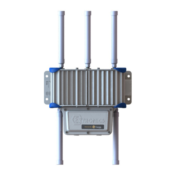
- Page 2 The Photograph on the front page shows the XN3 Aluminium Enclosure version. warranty information, refer Terms Conditions http://www.extronics.com © 2021 Extronics Limited. This document is Copyright Extronics limited. Extronics reserve the right to change this manual and its contents without notice, the latest version applies.
-
Page 3: Table Of Contents
XN3 Installation and Operating Manual Contents Introduction ....................4 Safety Information and Notes ................5 Storage of this Manual ................5 Special Conditions for Safe Use / Conditions particulières d’utilisation ....5 2.2.1 ATEX/IECEx ....................5 2.2.2 MET ......................5 List of Notes ..................... -
Page 4: Introduction
– such as the Extronics iANT2xx range of high quality rugged outdoor antennas. Any antennas not listed in the Extronics range must be assessed by the user to ensure they meet the requirements for installation of non-electrical equipment in hazardous areas. -
Page 5: Safety Information And Notes
XN3 Installation and Operating Manual 2 Safety Information and Notes 2.1 Storage of this Manual Keep this user manual safe and in the vicinity of the device. All persons required to work on or with the device should be advised on where the manual is stored. Conserver ce manuel d’utilisation en lieu sûr et à... -
Page 6: List Of Notes
XN3 Installation and Operating Manual 2.3 List of Notes The notes supplied in this chapter provide information on the following. • Warning! o Possible hazard to life or health. • Caution o Possible damage to property. • Important o Possible damage to enclosure, device or associated equipment. •... - Page 7 The XN3 enclosure must be secured only with the bolts supplied, and these must be tightened to the correct torque value. See Section 3.2.2 for details. Contact Extronics for replacement bolts. Avertissements! La plaque de protection de l’iWAP XN3 ne doit être fixée qu’avec les boulons fournis et serrés à...
- Page 8 XN3 Installation and Operating Manual Avertissements! Ne pas dépasser la puissance RF seuil pour le groupe d’équipement, dans lequel le XN3 et ses antennes doivent être installés doit être contrôlé conformément à la norme CEI 60079-0. Warning! The XN3 must not be modified in any way. Warning! Hazardous voltages are present within the XN3 enclosure.
- Page 9 XN3 Installation and Operating Manual Warning! Internal cells or batteries if applicable must only be replaced with cells or batteries of the same type. Avertissements! Les cellules ou batteries internes, le cas échéant, ne doivent être remplacées que par des cellules ou batteries du même type.
-
Page 10: Installation
XN3 Installation and Operating Manual 3 Installation 3.1 Mounting Mount the XN3 enclosure to a suitable structure, using the mounting points shown, Figure 1. The recommended fixings are: • M10 Flat Washer Form A DIN125A A4. • Socket Cap Head Screw M10 x 30 DIN912 A4-80 (minimum thread length of 30mm). - Page 11 XN3 Installation and Operating Manual Figure 1: Aluminium Enclosure Mounting Dimensions...
-
Page 12: Opening And Closing The Enclosure
XN3 Installation and Operating Manual 3.2 Opening and Closing the Enclosure 3.2.1 Opening the front cover plate • Remove all bolts using a metric hex key, Figure 2. Store the bolts carefully to avoid damage or loss. • Ensure care is taken when removing the cover. Do not use a screwdriver or any other sharp implement to prise the cover apart as it may damage the sealing gasket. -
Page 13: Cable Entries
Remove cover plate and keep bolts for reassembly o When refitting cover plate, only use supplied bolts and tighten to torque 3.5Nm. Check seal position and condition. o Check with Extronics for more information if required. Figures 3: XN3 entries and connectors... -
Page 14: Earthing
XN3 Installation and Operating Manual 3.4 Earthing 3.4.1 Location of XN3 enclosure external earth bond points There are M6 threaded earth boss bonding point situated within the junction box, Figure 4, external Figure 5. Removal of the front cover plate is required to access the area. -
Page 15: Electrical Installation
XN3 Installation and Operating Manual 3.5 Electrical Installation View inside junction box: Interface Plate See Figure 6 and Table1. Figure 6: XN3 Internal Connections Showing All Options... -
Page 16: Power Supply / Input Connector
XN3 Installation and Operating Manual Designator Purpose Comments Mains (L,N,E) or DC (+,-,E) input, Power input dependent on product configuration. Can be replaced by a blanking plate, Fibre input cabled to depending on product options. None separate dual LC fibre configurations will be supplied coupler. -
Page 17: Fuse Rating
The XN3 should be installed on a circuit with a double-pole circuit breaker of a maximum rating of 25A. This is the maximum current rating of the smallest internal chassis earth bond in accordance with EN60950-1 2.6.3.3. Refer to Extronics if it becomes necessary to exceed this rating. 3.9 Data Connections 3.9.1 Copper Ethernet... -
Page 18: Optical Fibre
XN3 Installation and Operating Manual 3.9.3 Optical Fibre The XN3 optical fibre format, Table 3, may be any of the following, refer to product option code #5 for details. Other optical formats are available on request. 1000Bas LC Duplex -3 to -9.5dBm -19dBm -1dBm 1310nm... -
Page 19: Intrinsically Safe Rf Outputs
XN3 Installation and Operating Manual 3.10 Intrinsically Safe RF Outputs Refer to Figure 9 for location of Intrinsically Safe RF outputs. 3.10.1 Example of RF threshold power calculation The following example shows how the RF threshold power may be calculated: Maximum transmitter output power (from transmitter datasheet) = 20dBm (100mW) Coaxial cable loss = 2dB... -
Page 20: Antenna Requirements
Antennas connected to the XN3 Intrinsically Safe RF outputs must be assessed as ‘simple apparatus’ in accordance with IEC 60079-11. Antennas supplied by Extronics for use with the XN3 already meet these requirements. It is possible to assess other antennas for this purpose, contact Extronics for details. -
Page 21: Ex Main Enclosure Test
XN3 Installation and Operating Manual If antennas are sited remotely from the XN3 flameproof enclosure, any metallic parts of the antennas must be isolated from earth by >500V , to prevent r.m.s hazardous earth currents from flowing in the coaxial cable. 3.13 Ex Main Enclosure Test If required, the integrity of the main enclosure sealing can be checked. -
Page 22: Cleaning And Maintenance
XN3 Installation and Operating Manual 4.3 Cleaning and Maintenance The XN3 and all its components require no maintenance. All work on the XN3 by personnel who are not expressly qualified for such activities will cause the Ex approval and the guarantee to become void. 4.4 Cleaning and Maintenance Intervals The cleaning intervals depend on the environment where the system is installed. -
Page 23: Pole Mounting
XN3 Installation and Operating Manual 5 Pole Mounting Using the clamp brackets (1) and (2) place them Align the pole mounting bracket (1) with the end together as shown. of the rail (2) and slide it down the rail as shown. Align the square nut (3) on one side and secure Align the fixing nut (3) and repeat the process. -
Page 24: Technical Data
XN3 Installation and Operating Manual 6 Technical Data... -
Page 25: Marking Information
Alternative ambient temperature ranges may be specified depending on the service temperature of installed equipment. • Alternative coding when Extronics iSOLATE501 is installed for DC isolation: II 3 (1) G Ex ec [ia Ga] nR IIC T6 Gc D Ex [ia Da] tc IIIC T85°C Dc •... -
Page 26: Met
Alternative ambient temperature ranges may be specified depending on the service temperature of installed equipment. • Alternative coding when Extronics iSOLATE501 is installed for DC isolation: o Class I, Zone 2 AEx ec [iaGa] nR IIC T6 Gc o Class II, Zone 22 AEx [iaDa] tc IIIB T85 C Dc •... -
Page 27: Type Codes
XN3 Installation and Operating Manual 8 Type Codes Refer to iWAP XN3 datasheet. The iWAP XN3 conforms to the following standards: 8.1.1 ATEX/IECEx • BS EN 60079-0: 2018 • BS EN 60079-7: 2015+A1:2018 • BS EN 60079-11: 2012 • BS EN 60079-15: 2019 •... -
Page 28: Eu Declaration Of Conformity
XN3 Installation and Operating Manual 9 EU Declaration of Conformity... - Page 29 XN3 Installation and Operating Manual...
Need help?
Do you have a question about the iWAP XN3 X2000 and is the answer not in the manual?
Questions and answers