Table of Contents
Advertisement
Quick Links
Advertisement
Table of Contents

Related Manuals for extronics iWAP XN3 X2000

Summary of Contents for extronics iWAP XN3 X2000
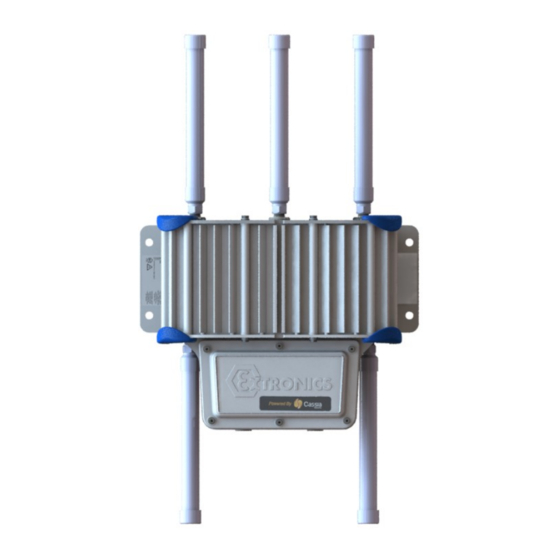
- Page 1 INSTALLATION AND OPERATING MANUAL...
- Page 2 XN3 Installation and Operating Manual [This Page is intentionally Blank]...
-
Page 3: Table Of Contents
XN3 Installation and Operating Manual Contents Introduction ....................4 Safety Information and Notes ................5 Storage of this Manual ................5 Special Conditions for Safe Use / Conditions particulières d’utilisation ....5 2.2.1 ATEX/IECEx ....................5 2.2.2 MET ......................5 List of Notes ..................... -
Page 4: Introduction
With IP66 / Type 4 (NEMA standards) ingress protection and a Marine grade copper-free aluminium alloy, e-coat with epoxy powder coated enclosure plus the option of surge protection, the iWAP XN3 X2000 is suitable for a wide variety of industrial and off-shore locations including chemical and pharmaceutical plants, oil refineries, FPSOs and oil and gas platforms. -
Page 5: Safety Information And Notes
XN3 Installation and Operating Manual 2 Safety Information and Notes 2.1 Storage of this Manual Keep this user manual safe and in the vicinity of the device. All persons required to work on or with the device should be advised on where the manual is stored. Conserver ce manuel d’utilisation en lieu sûr et à... -
Page 6: List Of Notes
Refer to Section 3.4 for details. The cover plate earth bond must not be removed. Avertissements! L’iWAP XN3 X2000 doit être mis à la terre. Il doit être raccordé au système de mise à la terre de l’installation, en utilisant au moins un des points externes de liaison à... - Page 7 Avertissements! L’iWAP XN3 X2000 ne doit être monté qu’avec des composants d’entrée de câbles correctement évalués. Warning! When PoE is used to power the iWAP XN3 X2000 in a C1D2 location, the source must be an NRTL certified device with outputs compliant with IEEE 802.3af/at.
- Page 8 XN3 Installation and Operating Manual Warning! Do not exceed the RF Threshold Power for the equipment group in which the iWAP XN3 X2000 and its antennas are to be installed; it must be controlled in accordance with IEC 60079- 0, and must not exceed the following levels: IIC –...
- Page 9 XN3 Installation and Operating Manual Warning! Special access: If the main enclosure is opened, integrity of main enclosure sealing must confirmed competent person Avertissements! Accès special: Si le boîtier principal est ouvert, l’intégrité de son étanchéité doit être confirmée par une personne compétente.
-
Page 10: Installation
XN3 Installation and Operating Manual 3 Installation 3.1 Mounting Mount the XN3 X2000 enclosure to a suitable structure, using the mounting points shown. Figure 1: Aluminium Enclosure Mounting Dimensions... -
Page 11: Opening And Closing The Enclosure
XN3 Installation and Operating Manual 3.2 Opening and Closing the Enclosure 3.2.1 Opening the front cover plate • Remove all bolts using a metric hex key. Store the bolts carefully to avoid damage or loss. • Ensure care is taken when removing the cover. Do not use a screwdriver or any other sharp implement to prise the cover apart as it may damage the sealing gasket. -
Page 12: Cable Entries
Remove cover plate and keep bolts for reassembly o When refitting cover plate, only use supplied bolts and tighten to torque 3.5Nm per 3.2.2. Check seal position and condition. o Check with Extronics for more information if required. -
Page 13: Earthing
XN3 Installation and Operating Manual 3.4 Earthing 3.4.1 Location of XN3 X2000 enclosure external earth bond points There are M6 threaded earth boss bonding point situated within the junction box, Figure 4. Removal of the front cover plate is required to access the area. Before putting in service: •... -
Page 14: Electrical Installation
XN3 Installation and Operating Manual 3.5 Electrical Installation View inside a representative junction box: Interface Plate See Figure 6 and Table1. Figure 6: XN3 Internal Connections Showing All Options... -
Page 15: Power Supply / Input Connector
The XN3 should be installed on a circuit with a double-pole circuit breaker of a maximum rating of 25A. This is the maximum current rating of the smallest internal chassis earth bond in accordance with EN60950-1 2.6.3.3. Refer to Extronics if it becomes necessary to exceed this rating. -
Page 16: Data Connections
XN3 Installation and Operating Manual 3.9 Data Connections 3.9.1 Copper Ethernet Information Check that the line speed of the switch port to which the XN3 X2000 is connected matches the XN3 X2000 port configuration, otherwise communication may not be established. If Copper Ethernet is specified, this will be terminated in a standard CAT5E/CAT6E RJ45 Socket on the front plate of the XN3 X2000, Position D in Figure 6. -
Page 17: Intrinsically Safe Rf Outputs
XN3 Installation and Operating Manual 3.10 Intrinsically Safe RF Outputs Refer to Figure 8 for location of Intrinsically Safe RF outputs. 3.10.1 Example of RF threshold power calculation The following example shows how the RF threshold power may be calculated: Maximum transmitter output power (from transmitter datasheet) = 20dBm (100mW) Coaxial cable loss = 2dB... - Page 18 XN3 Installation and Operating Manual Representative Configuration Example – Remote Mount Antennas Non-hazardous area Hazardous area Notes: Marking of iWAP Antenna installed to XN3 must be observed IEC 60079-14: 2014 when locating antenna in Clause 16.2.3 hazardous location Coaxial cable Intrinsically safe outputs.
-
Page 19: Antenna Requirements
It is possible to assess other antennas for this purpose, contact Extronics for details. 3.12 Antenna Installation Antennas approved by Extronics for use with the may either be fitted XN3 X2000 directly to the RF connectors of the unit or via a length of coaxial cable. -
Page 20: Intended Purpose Usage
XN3 Installation and Operating Manual 4 Intended Purpose Usage is built using modern components and is extremely reliable in XN3 X2000 operation. It must only be used for its intended purpose. Please note that the intended purpose also includes compliance with the instructions issued by the manufacturer for installation, setting up and service. -
Page 21: Pole Mounting
XN3 Installation and Operating Manual 5 Pole Mounting • Using the clamp brackets (1) and (2) place • Align the pole mounting bracket (1) with the end them together as shown. of the rail (2) and slide it down the rail as •... -
Page 22: Marking Information
XN3 Installation and Operating Manual 6 Marking information 6.1.1 ATEX/IECEx • Um = 60Vdc or 253Vac depending on customer specification. -
Page 23: Met
XN3 Installation and Operating Manual 6.1.2 MET... -
Page 24: Type Codes
XN3 Installation and Operating Manual 7 Type Codes Refer to iWAP XN3 X2000 datasheet. The iWAP XN3 X2000 conforms to the following standards: 7.1.1 ATEX/IECEx • BS EN 60079-0: 2018 • BS EN 60079-7: 2015+A1:2018 • BS EN 60079-11: 2012 •... -
Page 25: Eu Declaration Of Conformity
XN3 Installation and Operating Manual 8 EU Declaration of Conformity... - Page 26 XN3 Installation and Operating Manual...
- Page 27 XN3 Installation and Operating Manual [This Page is intentionally Blank]...
- Page 28 Terms Conditions http://www.extronics.com © 2021 Extronics Limited. This document is Copyright Extronics limited. Extronics reserve the right to change this manual and its contents without notice, the latest version applies.
Need help?
Do you have a question about the iWAP XN3 X2000 and is the answer not in the manual?
Questions and answers