Advertisement
Features
- 1 x 120W at 4ohms, for commercial and industrial use
- Lo-Z(8/4/2 ohms) / Hi-Z(70/100V) Compatible
- BluetoothⓇ / Front-panel input for portable player
- 4 inputs(2 Line, 2 Mic) and 1 output
- Priority Ducker and Feedback Suppressor for Mic.
- Priority muting with PTT switch
- Dynamic Loudness and Leveler for comfortable BGM
- Preset EQ and HPF for Loudspeakers
- Setup done locally from rear panel
- Expandable with optional power amplifier PCA1120
- 1U Rack mountable (with optional IRK-44-3)
Package Contents
- Main Unit
- Instruction Manual (This Document)
- AC Power Cord
- Safety Information
- 5-pin Euroblocks (3)
- Warranty Card
 This product is intended for commercial/professional use. It should be installed only by a specially-trained technician.
System Configuration Examples
See website for detailed connections.
Example A
Standalone use of the MCA1120 as a Background Music(BGM) and Paging system.

Example B
Expanding the system using the PCA1120(x2 shown) and additional speakers.

In this configuration with multiple rooms and speaker types, the MCA1120 controls the overall volume of the system, while each PCA1120 volume level can be adjusted for its room.
Example C
(IMAGE NOT SHOWN)
Driving a passive subwoofer with the PCA1120.
The PCA1120 has built-in crossover settings for this application.
Setup and Operation Steps

MCA1120 Rear Panel

- AC Inlet( IEC C13, 100V-240V 50/60 Hz) (⇒ see Step 5)
- SPEAKER OUT Terminals( Euroblock)
NOTE
It is important to read" Step 2: Connecting Speakers" before attempting to use this terminal.
IMPROPER SETUP CAN RESULT IN MALFUNCTION OR FIRE. (⇒ see Step 2) - Remote Volume Controller Terminal(Euroblock)
Use for connecting a commercially available volume control. (⇒ see Option 2) - MIC 2 / LINE 3 Input Terminals(Euroblock)
Use for connecting either a Mic Level or Line Level device. (⇒ see Step 4) - Manual Mute Terminal for MIC 1 Input( Euroblock)
Use for connecting a Push-to-Talk switch for Priority Mute Paging. (⇒ see Step 4) - MIC 1 Input Terminals( Euroblock)
Use for connecting a wired microphone. (⇒ see Step 4)
For wireless microphone systems, use MIC 2 / LINE 3 terminal. - PRE OUT Terminal(RCA Mono)
This is a variable line output linked to the Master Volume.
Use this output to link to expansion amplifier PCA1120 like in Example B. (⇒ see Option 1 for Setup) - LINE 2 Input Terminals( RCA Stereo)
Use to connect an external player such as CD, Music Streamer, etc. (⇒ see Step 3) - IR IN( 3.5mm Mini, Mono / 2-pole) For use with an external infrared controller.
- RS232( 3.5mm Mini, Stereo / 3-Pole)
For use with an external controller, or for Custom EQ programming.
![]()
To prevent damage, unplug the power cord when inserting/removing the RS232 cable. - DIP Switches
See Step 1 for instructions on how to set the DIP switches.

DIP Switch Settings
- Step 1-A: [ SET UP ] Initial Setup Switches
![]()
Incorrect settings can damage your equipment.
Set up carefully to ensure safe operation.
![]()
DIP Switch setting changes will not apply until the unit is power cycled by removing the AC power cord for a while, and reinserting.
#1 [ Keylock ]
Locks the front panel controls with the exception of the Power button and Master Volume.
![Initial Setup Switches - #1 [ Keylock ]](http://static-data2.manualslib.com/pdf7/297/29617/2961619-onkyo/images/onkyo-mca1120-initial-setup-switches-1-keylock-89fe3.png "Onkyo - MCA1120 - Initial Setup Switches - #1 [ Keylock ]")
#2 [ Auto Standby ]
The MCA1120 automatically goes into the standby state after two hours when there is no audio signal and no operation.
![Initial Setup Switches - #2 [ Auto Standby ]](http://static-data2.manualslib.com/pdf7/297/29617/2961619-onkyo/images/onkyo-mca1120-initial-setup-switches-2-auto-standby-a5cee.png "Onkyo - MCA1120 - Initial Setup Switches - #2 [ Auto Standby ]")
NOTE:Auto Standby does not work when Bluetooth is connected.
#3, 4 [ Auto Power On ]
When an audio signal is detected on the selected input during Standby, the power is turned on automatically.
![Initial Setup Switches - #3, 4 [ Auto Power On ]](http://static-data2.manualslib.com/pdf7/297/29617/2961619-onkyo/images/onkyo-mca1120-initial-setup-switches-3-4-auto-power-on-45e86.png "Onkyo - MCA1120 - Initial Setup Switches - #3, 4 [ Auto Power On ]")
#5 [ Volume Control ]
Select which type of optional external volume controller: Volume Control(10kΩ、B-curve type), or Infrared Remote System.
![Initial Setup Switches - #5 [ Volume Control ]](http://static-data2.manualslib.com/pdf7/297/29617/2961619-onkyo/images/onkyo-mca1120-initial-setup-switches-5-volume-control-64109.png "Onkyo - MCA1120 - Initial Setup Switches - #5 [ Volume Control ]")
#6 [ MIC 2 / LINE 3 ]
Choose between MIC (Mono) or LINE (Stereo) input setting.
![Initial Setup Switches - #6 [ MIC 2 / LINE 3 ]](http://static-data2.manualslib.com/pdf7/297/29617/2961619-onkyo/images/onkyo-mca1120-initial-setup-switches-6-mic-2-line-3-4e4ec.png "Onkyo - MCA1120 - Initial Setup Switches - #6 [ MIC 2 / LINE 3 ]")
#7 [ MIC 2 AMP ]
If switch #6 is set to MIC 2, select between On (Mic Level) or Off (Line Level).
![Initial Setup Switches - #7 [ MIC 2 AMP ]](http://static-data2.manualslib.com/pdf7/297/29617/2961619-onkyo/images/onkyo-mca1120-initial-setup-switches-7-mic-2-amp-02482.png "Onkyo - MCA1120 - Initial Setup Switches - #7 [ MIC 2 AMP ]")
#8 [ SPEAKER OUT ]
Select Hi-Z or Lo-Z depending on your speaker specifications.
![Initial Setup Switches - #8 [ SPEAKER OUT ]](http://static-data2.manualslib.com/pdf7/297/29617/2961619-onkyo/images/onkyo-mca1120-initial-setup-switches-8-speaker-out-227b4.png "Onkyo - MCA1120 - Initial Setup Switches - #8 [ SPEAKER OUT ]")
NOTE: It is important to read" Step 2: Connecting Speakers" before setting this switch. IMPROPER SETUP CAN RESULT IN MALFUNCTION OR FIRE. (⇒ see Step 2 for details)
#9 [ Speaker Lo-Z ]
If Switch #8 is set to Lo-Z, you must adjust this switch according to your speaker specifications.
![Initial Setup Switches - #9 [ Speaker Lo-Z ]](http://static-data2.manualslib.com/pdf7/297/29617/2961619-onkyo/images/onkyo-mca1120-initial-setup-switches-9-speaker-lo-z-e16ea.png "Onkyo - MCA1120 - Initial Setup Switches - #9 [ Speaker Lo-Z ]")
NOTE: It is important to read" Step 2: Connecting Speakers" before setting this switch. IMPROPER SETUP CAN RESULT IN MALFUNCTION OR FIRE. (⇒ see Step 2 for details)
#10 NOT USED
- Step 1-B: [ SOUND MODE ] Sound Preferences Switches
Advanced configuration tools for Paging, EQ and DSP.
TIP: These setting changes are instant. No power cycle is necessary.
#1 [ Mic Ducker ]
When the ducker senses audio from MIC 1 and/or MIC 2(not LINE 3), the volume of all other input sources will be attenuated by 24dB. This is useful for paging over background music.
![Sound Preferences Switches - #1 [ Mic Ducker ]](http://static-data2.manualslib.com/pdf7/297/29617/2961619-onkyo/images/onkyo-mca1120-sound-preferences-switches-1-mic-ducker-52b2f.png "Onkyo - MCA1120 - Sound Preferences Switches - #1 [ Mic Ducker ]")
If you set #6 [ MIC 2 / LINE 3 ] of SET UP DIP switch to [ MIC 2 ], you can use this function with two microphones.
#2 [ Auto Leveler ]
Automatically adjusts the level of each input signal for consistent volume across sources.
![Sound Preferences Switches - #2 [ Auto Leveler ]](http://static-data2.manualslib.com/pdf7/297/29617/2961619-onkyo/images/onkyo-mca1120-sound-preferences-switches-2-auto-leveler-3a1ae.png "Onkyo - MCA1120 - Sound Preferences Switches - #2 [ Auto Leveler ]")
#3-5 [ HPF (High Pass Filter) ]
Use this filter to limit bass frequencies to the SPEAKER OUT terminals. The DIP switches set the cutoff frequency.
![Sound Preferences Switches - #3-5 [ HPF (High Pass Filter) ]](http://static-data2.manualslib.com/pdf7/297/29617/2961619-onkyo/images/onkyo-mca1120-sound-preferences-switches-3-5-hpf-high-pass-1269a.png "Onkyo - MCA1120 - Sound Preferences Switches - #3-5 [ HPF (High Pass Filter) ]")
NOTE : Do not set to [ Off ] when using Hi-Z speaker or the amplifier may go into protection mode.
#6,7 [ BGM Mode ]
elect a Sound Mode based on the intended" mood" of the listening environment.
![Sound Preferences Switches - #6,7 [ BGM Mode ]](http://static-data2.manualslib.com/pdf7/297/29617/2961619-onkyo/images/onkyo-mca1120-sound-preferences-switches-6-7-bgm-mode-e16d2.png "Onkyo - MCA1120 - Sound Preferences Switches - #6,7 [ BGM Mode ]")
#8-10 [ Preset EQ for Loudspeaker ]
Select the EQ preset for your speaker type(see list below).
![Sound Preferences Switches - #8-10 [ Preset EQ ]](http://static-data2.manualslib.com/pdf7/297/29617/2961619-onkyo/images/onkyo-mca1120-sound-preferences-switches-8-10-preset-eq-85acc.png "Onkyo - MCA1120 - Sound Preferences Switches - #8-10 [ Preset EQ ]")
Connecting Speakers
Pay close attention to speaker setting / connection!
It may cause malfunction or fire.
- Connect AC power cord in final step. Do not connect AC power cord before this step. It may cause electric shock.
- Check the connection pins of Euroblock and Lo-Z / Hi-Z settings of DIP switches according to speaker specifications.
If these are not matched, it may cause malfunction or fire.
- Hi-Z (High Impedance) Connections
 Connections")
 Connections")
- Set #8 [ SET UP ] DIP switch [ SPEAKER OUT ] to [ Hi-Z ].
- Connect the [ 100V ] or [ 70V ] terminal of SPEAKER OUT tothe + terminal on your speakers. Next, connect the [ COM ] to the ‒ terminal on your speakers.
- Do not use the high impedance 70V line and 100V line terminals at the same time.
- Make sure that the total rated input power of the connected speakers is 120W or less.
- Lo-Z (Low Impedance) Connections
 Connections")
 Connections")
- Set #8 [ SET UP ] DIP Switch [ SPEAKER OUT ] to [ Lo-Z ].
- Connect the + terminal of SPEAKER OUT to the + terminal on your speakers.
Next, connect the - to the ‒ terminal on your speakers.
- Do not connect the Lo-Z speakers to the Hi-Z terminals.
- When connecting multiple speakers, make sure that the total impedance is more than the value of setting #9 [ Speaker Lo-Z ] of SET UP DIP switch.
Connecting External Players
Stereo signals are internally mixed into mono.
- LINE 1 Connection
See the "front panel" section on the back. - LINE 2 Connection

- Connect the external player to the LINE 2 terminals with the RCA cable.
You can use either L or R terminal for the output of monaural player.
- Connect the external player to the LINE 2 terminals with the RCA cable.
- LINE 3 Connection


- Set #6 [ SET UP ] DIP Switch [ MIC 2 / LINE 3 ] to [ LINE 3 ].
If this setting is missing, the in-phase signal (melody, bass line, etc.) will not come out. - Connect the output of the external player to the LINE 3 terminal with Euroblock.
You can use either L or R terminal for the output of monaural player.
Connecting Microphones
- Mic Ducker and Feedback Suppressor can be used with either MIC 1/2.
- Connect the microphone with paging function to MIC 1, and wireless microphone to MIC 2.
- Since there is no phantom power, use battery-powered condenser microphone.
- Normal dynamic microphone can be used with either MIC 1/2 Input.
- MIC 1 Connection

(Microphone with contact
No-voltage contact
Short-circuit current: 3 mA or less
Open circuit voltage: DC 24 V or less
NOTE:
H (Hot, +),
C (Cold, -),
E (Earth, GND)
Using a 2-core shielded wire
From microphone
Using a single-core shielded wire
From microphone
Short the terminals
between [C] and [E])

- Connect the output of the microphoneto the MIC 1 terminal with Euroblock.
- If necessary, connect the PTT shielded wire shielded wire (Push-To-Talk) switch for paging From microphone From microphone to the MANUAL MUTE [+] / [-] terminals
You can mute the input sound other than MIC 1 while pressing the PTT switch.
(Paging Function)
-
MIC 2 Connection


- Set #6 [ SET UP ] DIP Switch [ MIC 2 / LINE 3 ] to [ MIC 2 ].
- Use #7 [ SET UP ] DIP Switch [ MIC2 AMP ] to select between[ On ] (Mic level) or [ Off ] (Line Level).
If using a wireless MIC, this selection should be based off of the output level of the microphone receiver unit. - Connect the output of the microphone to the MIC 2 terminal with Euroblock.
For the connection method of the shielded wire, refer to the section on MIC 1 Connection.
Connecting Power Cord

- Connect the supplied AC power cord to the AC Inlet and plug to AC outlet.
Option 1: Expanding Speakers with PCA1120

- Connect the PRE OUT terminal ofthe MCA1120 and the LINE IN terminal (L or R) of PCA1120 with the monaural RCA cable.
- Follow the instruction manual ofthe PCA1120, set the DIP switch and connect the speaker.
- For further expansion, connect toanother PCA1120 in series from the LINE OUT terminal of the PCA1120.
Benefits of combining MCA1120 with one or more PCA1120(s).
- Additional speaker zones can be added (See Example B).
- A passive subwoofer can be added to the system (See Example C).
- Both the MCA1120 and PCA1120 include independent Preset EQ and HPF, allowing you totailor the sound of each speaker area.
- The MCA1120 Master Volume control can be used to adjust overall system volume forall areas since its PRE OUT terminal is variable. In this application, set the PCA1120 volume control to the center position (12 o'clock). Alternatively, you can adjust each PCA1120 volume independently.
Option 2: Remote Volume Control
- Remote volume control by 10kΩ potentiometer. Remote volume and master volume function in series. If either is at minimum, there will be no sound.


- Set to [ Volume Control(10kΩ) ] of #5 [ Volume Control ] ofSET UP DIP switch.
- Connect the external volume(10kΩ, B-curve) to the Remote VolumeController terminal with Euroblock.
Installing your amplifier
Do not block any ventilation openings.
By playing your equipment at higher level for a long period, the protection circuit maybe activated by high temperature and the sound may drop.
-
Rack Mount
- Remove four feet from the bottom of the unit.

- Attach the rack mount brackets IRK-44-3 by referring to the instruction manual.
- Install the unit in your rack system.

- Stacking Amplifiers
When stacking amplifiers without using a cabinet, keep enough space from the top surface of the unit.
Do not remove feet for air ventilation.


Since some parts such as cooling fans are consumable parts, it is necessary to replace the parts according to deterioration.
For replacement, please contact the store you purchased or Onkyo service.
Specification

*1: MIC 2 and LINE 3 are exclusive inputs. Only one can be used.
| Bluetooth & USB | |
| Communication System | Version5.0 |
| Communication Range | Max. 10m (Line of sight approx.) |
| USB Power Supply | 5V/2.1A (Not For Audio Playback) |
| General | |
| Operating Temperature | 0 - 40 ℃ @ Non-condensing |
| Power Supply | AC100 - 240V(50/60 Hz) |
| Power Consumption | 215W @ Rated Power, 10W @ Idling |
| Dimensions | 1 RU high (w/o Foots), half rack wide |
| 8.5 W x 2.2 H x 12.6 D [ inch ](w/o legs 1.75H) | |
| 215 W x 55 H x 319 D [ mm ](w/o legs 44.5H) | |
| Product Weight | 3.6kg(7.9lbs) |
| Option | Power Amplifier: PCA1120 |
| Rack Mount Kit: IRK-44-3 | |
Specifications and features are subject to change without notice.
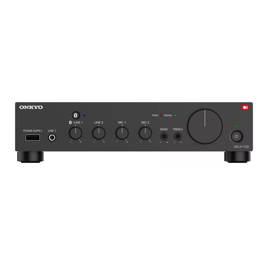
MCA1120 Front Panel

- USB Power Supply Terminal (5V / 2.1A)
- LINE 1 Input Terminals (3.5mm Mini, Stereo)
Connect a portable audio player, tablet, etc..
NOTE: When you connect a device into LINE 1 input during Bluetooth playback, Bluetooth audio stops and LINE 1 sound will be output. - [
![]() ] Bluetooth Button / Indicator
] Bluetooth Button / Indicator
Connect Bluetooth-enabled device such as portable audio player, tablet, etc.
During pairing mode, the indicator blinks. When the indicator is lit, the device is connected.
NOTE: When you connect a device via Bluetooth while LINE 1 input is being used, LINE 1 input sound will stop and Bluetooth sound will be output. - Input Volume LINE 1(Bluetooth) / LINE 2 / MIC 1 / MIC 2 (LINE 3)
To Adjust each input level.
To adjust the level of LINE 3, use knob for MIC 2. - SIGNAL / PEAK Indicator
SIGNAL Indicator
It lights up when the speaker output level becomes around - 46 dB or more of the rated output.
It may not light up when the output level is low. It is not malfunction. Blinks when muted. (Muting function is done only by IR IN or RS232. This unit does not have this operation.)
PEAK indicator
Lights up when the speaker output level reaches its peak (around - 3 dB from the rated output).
If it lights continuously, the sound maybe distorted. Lower the volume if necessary. - BASS / TREBLE
You can adjust BASS (low frequency) and TREBLE (high frequency) from -10 dB to +10 dB. Use a small screwdriver, etc. . - Master Volume
Adjust the output level to the speaker and PRE OUT jack. Turning it to the right will increase the volume. If you add PCA1120, you can raise or lower the system volume by this knob. - [
![]() ] Power Button / Indicator
] Power Button / Indicator
Switch the Power Standby / On. The indicator lights up as follows.
Standby - Red
On - Green
BluetoothⓇ Operation
You can wirelessly play music on a Bluetooth-enabled device, such as a portable audio player, tablet, etc. USB POWER SUPPLY terminal supplies power to USB compatible devices.
 (When Bluetooth wireless connection does not work, wire connect to LINE 1.)
- Pairing
- While the power of this unit is on, press the Bluetooth button.
The indicator flashes and this unit is into pairing mode. - Enable (turn on) the Bluetooth function of the source device (tablet, etc.),and then select "Onkyo MCA1120 XXXXXX".
If a password is requested, enter "0000".
When the pairing is completed, the indicator lights steadily.
To connect another Bluetooth device, repeat from step 1. This unit can store maximum eight devices.
- While the power of this unit is on, press the Bluetooth button.
- Playing Back
- While the power of this unit is on, make a Bluetooth connection of a tablet, etc. and this unit.
- Play music files.
- Raise the volume of the tablet etc..
When you connect a device to LINE 1 input terminal during Bluetooth connection, the Bluetooth audio stops and LINE 1 sound will be output.
 The BluetoothⓇ word mark and logos are registered trademarks owned by Bluetooth SIG, Inc.
Adjusting Volume

Adjust the total volume and mixing level of the external players and microphones.
- Set the Input Volume to the position of the center (12 o'clock) connectedto the external source device used by the main.
- Keep the other input volumes to a minimum.
- Play back the BGM and adjust the master volume to the optimum volume.
- With the master volume decided in step 3 fixed, while outputting soundfrom other devices and microphones, gradually raise each input volume to balance the volume.
- If the volume is low even if the other input volume is maximized in step 4, lower the input volume in step 1 slightly and repeat from step 2.
Troubleshooting

More detailed information of "Troubleshooting" is posted on the Web.
If symptoms do not improve even if referring to them, please contact Onkyo service.

Keio Kanda Suda-cho Bldg. 8F, 2-5 Kanda Sudacho, Chiyoda-ku, Tokyo 101-0041 Japan
Printed in Malaysia
©ODS Corporation all rights reserved.
<U.S.A.>
18 Park Way, Upper Saddle River, N.J. 07458, U.S.A.
Tel: 800-225-1946, 201-818-9200 Fax: 201-785-2650
http://www.onkyoinstallation.com
<Germany>
Gutenbergstrasse 3, 82178 Puchheim, Germany Tel: +49-8142-4401-0 Fax: +49-8142-4208-213
https://www.eu.onkyo.com
<PRC>
302, Building 1, 20 North Chaling Rd., Xuhui District, Shanghai, China 200032,
Tel: +86-21-52131366 Fax: +86-21-52130396
http://www.cn.onkyo.com

Documents / Resources
References
Download manual
Here you can download full pdf version of manual, it may contain additional safety instructions, warranty information, FCC rules, etc.
Advertisement


Need help?
Do you have a question about the MCA1120 and is the answer not in the manual?
Questions and answers