Table of Contents
Advertisement
Quick Links
Advertisement
Table of Contents

Subscribe to Our Youtube Channel
Related Manuals for Fortec Star ADVANTECH AIMB-229


Summary of Contents for Fortec Star ADVANTECH AIMB-229
- Page 2 Manual ADVANTECH AIMB-229 Mini-ITX Motherboard with AMD® Ryzen V2000 Embedded Processor The information contained in this document has been carefully researched and is, to the best of our knowledge, accurate. However, we assume no liability for any product failures or damages, immediate or consequential, resulting from the use of the information provided herein.
- Page 3 User Manual AIMB-229 AMD V2000-series Quad Core Mini-ITX with 2 x HDMI, 2 x DP (Type-C), 8 x USB, 6 x COM, and 12V DC-in...
- Page 4 Copyright The documentation and the software included with this product are copyrighted 2022 by Advantech Co., Ltd. All rights are reserved. Advantech Co., Ltd. reserves the right to make improvements in the products described in this manual at any time without notice.
- Page 5 A Message to the Customer Advantech Customer Services Every Advantech product is built to the most exacting specifications to ensure reliable performance in the harsh and demanding conditions typical of industrial environ- ments. Whether your new Advantech equipment is destined for the laboratory or fac- tory floor, you can be assured that your product will provide the reliability and ease of operation for which the name Advantech has come to be known.
- Page 6 Memory Compatibility Normal RAM Test Data Category Speed Capacity Vendor ADVANTECH P/N DDR4 2666 Advantech SQR-SD4N4G2K6SNEFB DDR4 2400 Advantech SQR-SD4N4G2K4SNEFB DDR4 2666 Advantech SQR-SD4N8G2K6SNBCB DDR4 2133 Advantech AQD-SD4U8GN21-SG DDR4 3200 Advantech AQD-SD4U8GN32-SE DDR4 3200 16GB Advantech SQR-SD4N16G3K2SNCB DDR4 2666 16GB Advantech AQD-SD4U16N26-SE DDR4...
- Page 7 Initial Inspection Before installing the motherboard, ensure that the following items are included with the product: 1 x AIMB-229 AMD V2000-series Quad Core Mini-ITX motherboard 1 x SATA HDD cable 1 x SATA power cable 1 x Serial port cable (1-to-1) ...
- Page 8 AIMB-229 User Manual...
-
Page 9: Table Of Contents
Contents Chapter General Information ......1 Introduction ....................2 Features ....................2 Specifications .................... 2 1.3.1 Processor..................2 1.3.2 Expansion ..................2 1.3.3 Memory ..................2 1.3.4 Graphics Interface................. 2 1.3.5 Ethernet Interface ................. 2 1.3.6 SATA Interface................3 1.3.7 Rear I/O ..................3 1.3.8 Internal Connector ................ - Page 10 2.7.2 Reset (JFP1/RESET)..............20 2.7.3 HDD LED (JFP1/HDDLED) ............20 2.7.4 External Speaker (JFP1/SPEAKER) .......... 20 DC Input Jack and 4-Pin ATX Connector (DCIN1) ......... 21 SATA Signal and Power Connector (SATA1~SATA2/SATA_PWR1~2). 21 2.10 HD Analog Audio Interface (AUDIO1, AUDIO2, FPAUD1) ..... 22 2.11 PCI-E x8 Slot (PCIEX8_1) ..............
- Page 11 DC-IN Adaptor Connector (DCIN1)............72 HDMI Port Connector (HDMI12) ............. 72 USB31X2_DP2 ..................73 USB31X2_DP3 ..................74 USB34..................... 75 AT/ATX Mode Selection (PSON1) ............75 RJ45(LAN1+LAN2) Connector (LAN12) ..........76 HD Analog Audio Interface Line-Out (AUDIO1) ........76 HD Analog Audio Interface MIC-In (AUDIO2) ......... 77 A.10 Audio Amplifier Output Pin Header (AMP1) ..........
- Page 12 AIMB-229 User Manual...
-
Page 13: Chapter 1 General Information
Chapter General Information... -
Page 14: Introduction
Introduction AIMB-229 is a mini-ITX motherboard based on the AMD Ryzen™ embedded V2000 series processor. Designed with diverse I/O and 4 x display outputs, AIMB-229 is ideal for multi-display applications in digital surveillance, digital signage, electronic gaming machines, and thin client operations. Advantech’s WISE-PaaS/DeviceOn supports remote management software and enhances management efficiency. -
Page 15: Sata Interface
1.3.6 SATA Interface Max. Data Transfer Rate: 600 MB/s Channel: 2 x 1.3.7 Rear I/O DP: 2 x Ethernet: 2 x USB: 4 x (2 x USB 2.0, 6 x USB 3.2) Audio: 2 x (1 x Line-Out, 1 x Mic-In) ... -
Page 16: Jumpers And Connectors
Jumpers and Connectors The AIMB-229 motherboard features a number of jumpers and connectors that enable the integration of external devices, such as hard disk drives and a keyboard, and configuration according to specific applications. The function of each board jumper and connector is listed in the tables below. Later sections in this chapter provide instructions for setting jumpers. - Page 17 Table 1.1: Connector/Header List SATA power connector SATA_PWR2 ATX Power supply(5VSB) connector ATX_5VSB1 DDR3L SO-DIMM socket DIMMA1/DIMMB1 BIOS flash pin header BIOS1_CN1 COM2 box header COM2 SPI BIOS socket BIOS1 Dual port USB 2.0 pin header USB56 Serial ATA interface connector SATA1 eDP panel voltage selection JEDP1...
-
Page 18: Voltage Selection For Lvds1/Edp1 Connector (Jedp1)
1.4.1 Voltage Selection for LVDS1/EDP1 Connector (JEDP1) Function Jumper Setting Jumper position for +3.3V (default) Jumper position for +5V Jumper position for +12V 1.4.2 CMOS Clear (JCMOS1) Function Jumper Setting Keep CMOS data (default) Clear CMOS data 1.4.3 PWRBTN#/ RESET#/HDD LED/Serial Bus from HW Monitor IC/ Internal Buzzer/External Speaker Header (JFP1) Function Jumper Setting... -
Page 19: Watchdog Timer Output And Obs Beep (Jwdt1+ Jobs1)
1.4.4 Watchdog Timer Output and OBS Beep (JWDT1+ JOBS1) Function Jumper Setting Watchdog timer output (2-3) (default) OBS BEEP(4-5) (default) 1.4.5 AT/ATX Mode Selection (PSON1) Function Jumper Setting ATX mode (default) AT mode 1.4.6 Case Open Selection Pin Header (JCASEOP_SW1) Function Jumper Setting Normal close... -
Page 20: Com1_Ri# Pin Ri#/5V/12V Selection (Jsetcom1_V1)
1.4.7 COM1_RI# Pin RI#/5V/12V Selection (JSETCOM1_V1) Function Jumper Setting Jumper position for RI# (default) Jumper position for +5V Jumper position for +12V 1.4.8 COM4_RI# Pin RI#/5V/12V Selection (JSETCOM4_V1) Function Jumper Setting Jumper position for RI# (default) Jumper position for +5V Jumper position for +12V AIMB-229 User Manual... -
Page 21: Cctalk Power Voltage 5V/12V Select (Jcct_Vcon1)
1.4.9 CCTalk Power Voltage 5V/12V Select (JCCT_VCON1) Function Jumper Setting Jumper position for +12V (default) Jumper position for +5V Jumper and Connector Locations Top Layer Overview 13 13 14 14 47 47 19 9 40 40 39 39 23 23 24 24 25 25 36 36... - Page 22 Bottom Layer Overview Figure 1.2 Jumper and Connector Locations (Bottom Side) Table 1.3: Connector/Header List Description Part Reference DC-IN adaptor connector DCIN1 HDIM Port connector HDMI12 USB 3.0 Type A and Type C USB31X2_DP2+USB1 USB 3.0 Type A and Type C USB31X2_DP3+USB2 USB 3.1 Type A USB34...
- Page 23 Table 1.3: Connector/Header List M.2 M Key connector NGFF_M1 PCI-Express x8 slot PCIEX8_1 M.2 E Key connector M2E1 COM1 RI# selection pin header JSETCOM1_V1 LPC bus interface header LPC1 COM1 box header COM1 EDP Backlight inverter power connector INV1 System fan connector SYSFAN1 16-bits General Purpose I/O pin header GPIO1...
-
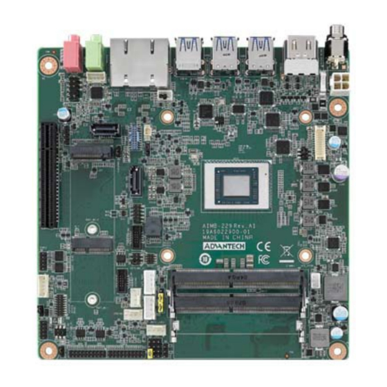
Page 24: Board Diagram
Board Diagram Figure 1.3 AIMB-229 Board Diagram Safety Precautions Warning! Always completely disconnect the power cord from the chassis before manual handling this device. Do not make connections while the power is on. Sensitive electronic components can be damaged by sudden power surges. -
Page 25: Jumper Settings
Jumper Settings This section provides instructions on how to configure the motherboard by setting jumpers. The information also includes the motherboards’ default settings and the options for each jumper. 1.8.1 How to Set Jumpers Users can configure the motherboard according to the specific application require- ments by setting the jumpers. -
Page 26: System Memory
System Memory AIMB-229 is equipped with two sockets for 260-pin SODIMM. These sockets are compatible with 1.2V unbuffered double-data-rate synchronous, low-voltage DRAM (DDR4 SDRAM). DRAM is available in 4, 8, 16, and 32 GB capacities. The socket supports any combination of DIMMs of any size, for a total memory size of 4 to 32 GB. -
Page 27: Chapter 2 Connecting Peripherals
Chapter Connecting Peripherals... -
Page 28: Introduction
Introduction Most of the connectors can be accessed from the top of the board during installation. If a number of cards are installed or the chassis is packed, the board may need to be partially removed in order to make all the connections. USB Ports (USB31X2_DP2+USB1/USB31X2_DP3+USB2/USB34/USB56) AIMB-229 provides up to 8 x USB ports (6 x USB 3.1 and 6 x USB 2.0 on the rear... -
Page 29: Displayport1/2/3/4
DisplayPort1/2/3/4 (HDMI12/ USB31X2_DP2+USB1/USB31X2_DP3+USB2) AIMB-229 features 4 x DP connectors. AIMB-229 User Manual... -
Page 30: Serial Ports (Com1 ~ Com6)
Serial Ports (COM1 ~ COM6) AIMB-229 supports six serial ports (COM1 and COM6 support RS-232 function, COM2 and COM5 support RS-232/422/485 function via jumper setting, COM3 colay CCTalk, and COM4 colay TTL). These ports can be connected to serial devices, such as a mouse or printer, or a communications network. -
Page 31: Cpu Fan Connector (Cpu_Fan1)
CPU Fan Connector (CPU_FAN1) This connector supports cooling fans of 500 mA (6 W) or less. System Fan Connector (SYSFAN1/2) This connector supports cooling fans of 500 mA (6 W) or less. AIMB-229 User Manual... -
Page 32: Power Switch/Hdd Led/Smbus/Speaker Pin Header (Jfp1), Power Led, And Keyboard Lock Pin Header (Jfp2)
Power Switch/HDD LED/SMBUS/Speaker Pin Header (JFP1), Power LED, and Keyboard Lock Pin Header (JFP2) There are several headers for monitoring and controlling the AIMB-229. 2.7.1 ATX Soft Power Switch (JFP1/PWR_SW) If your computer case is equipped with an ATX power supply, connect the power on/ off button on the computer case to JFP1/ PWR_SW for convenient operation. -
Page 33: Dc Input Jack And 4-Pin Atx Connector (Dcin1)
DC Input Jack and 4-Pin ATX Connector (DCIN1) SATA Signal and Power Connector (SATA1~SATA2/SATA_PWR1~2) AIMB-229 features a high-performance serial ATA III interface (up to 600 MB/s) that supports thin space-saving cables to streamline hard drive cabling. AIMB-229 User Manual... -
Page 34: Hd Analog Audio Interface (Audio1, Audio2, Fpaud1)
2.10 HD Analog Audio Interface (AUDIO1, AUDIO2, FPAUD1) The FPAUD1 connector is for a chassis-mounted front-panel audio I/O module that supports either HD Audio or legacy AC'97 (optional) standard. Connect this connector with the front-panel audio I/O module cable. Note! For motherboards with the optional HD Audio feature, we recommend connecting a high-definition front-panel audio module to this connector to take advantage of the motherboard's high-definition audio capability. -
Page 35: Pci-E X8 Slot (Pciex8_1)
2.11 PCI-E x8 Slot (PCIEX8_1) AIMB-229 provides 1 x PCI express x8 slot. 2.12 Low-Voltage Differential Signaling Interface (EDP1) AIMB-229 User Manual... -
Page 36: Lvds Backlight Inverter Power Connector (Inv1)
2.13 LVDS Backlight Inverter Power Connector (INV1) 2.14 NGFF M.2 B-Key and E-Key Connector (M2B1 & M2E1) AIMB-229 User Manual... -
Page 37: Audio Amplifier Output Connector (Amp1), Bom Optional
2.15 Audio Amplifier Output Connector (AMP1), BOM Optional 2.16 General Purpose I/O Pin Header (GPIO1) AIMB-229 User Manual... -
Page 38: General Purpose I/O Pin Header (Bios1)
2.17 General Purpose I/O Pin Header (BIOS1) 2.18 SPI Programming Pin Header (BIOS1_CN1) AIMB-229 User Manual... -
Page 39: Low-Pin-Count Header (Lpc1)
2.19 Low-Pin-Count Header (LPC1) 2.20 Case-Open Detect Connector (JCASE2) AIMB-229 User Manual... -
Page 40: Cmos Battery Connector (Bat1)
2.21 CMOS Battery Connector (BAT1) 2.22 DDR4 SODIMM Socket (DIMMA1, DIMMB1) AIMB-229 User Manual... -
Page 41: Bios Operation
Chapter BIOS Operation... -
Page 42: Introduction
Introduction With the AMI BIOS Setup program, users can modify the BIOS settings and control the device configuration. The Setup program features a number of menus for making changes and turning special features on or off. This chapter describes the basic nav- igation of the AIMB-229 BIOS menus. -
Page 43: Main Menu
3.2.1 Main Menu Press <Del> to enter the AMI BIOS CMOS Setup Utility. The Main menu will appear onscreen. Use the arrow keys to select an item and press <Enter> to accept or enter the sub-menu. The Main BIOS setup screen has two main frames. The left frame displays all the options that can be configured. -
Page 44: Advanced Bios Features
3.2.2 Advanced BIOS Features Select the Advanced tab from the BIOS setup menu to enter the Advanced BIOS setup screen. Users can select any of the items in the left frame of the screen, such as CPU Configuration, to access the sub-menu for that item. Display an Advanced BIOS setup option by highlighting it using the <Arrow>... - Page 45 3.2.2.1 Trusted Computing This item allows users to enable/disable the TPM (TPM 2.0). The TPM (Trusted Plat- form Module) is a secure key generator and key cache management component that enables protected storage of encryption keys and authentication credentials for enhanced security.
- Page 46 Enable ACPI Auto Configuration [Disabled] This item allows users to enable/disable BIOS ACPI auto configuration. Enable Hibernation [Enabled] This item allows users to enable/disable the Hibernate (OS/S4 sleep state) func- tion. This option may not be available with certain operating systems. ACPI Sleep State [Auto] ...
- Page 47 3.2.2.3 NCT6126D Super IO Configuration 3.2.2.4 Super IO Chip [NCT6126D] Serial Port 1 Configuration AIMB-229 User Manual...
- Page 48 Serial Port [Enabled] – Device Settings: IO = 3F8h; IRQ = 4 – Change Settings [Auto] This item allows users to select the optimal settings for serial port 1. Serial Port 2 Configuration AIMB-229 User Manual...
- Page 49 Serial Port [Enabled] – Device Settings: IO = 2F8h; IRQ = 3 – Change Setting [Auto] This item allows users to select the optimal settings for serial port 2. Serial Port 3 Configuration AIMB-229 User Manual...
- Page 50 Serial Port [Enabled] – Device Settings: IO = 3E8h; IRQ = 5 – Change Setting [Auto] This item allows users to select the optimal settings for serial port 3. Serial Port 4 Configuration AIMB-229 User Manual...
- Page 51 Serial Port [Enabled] – Device Settings: IO = 2E8h; IRQ = 5 – Change Setting [Auto] This item allows users to select the optimal settings for serial port 4. Serial Port 5 Configuration AIMB-229 User Manual...
- Page 52 Serial Port [Enabled] – Device Settings: IO = 220h; IRQ = 11 – Change Setting [Auto] This item allows users to select the optimal settings for serial port 5. Serial Port 6 Configuration AIMB-229 User Manual...
- Page 53 Serial Port [Enabled] – Device Settings: IO = 228h; IRQ = 11 – Change Setting [Auto] This item allows users to select the optimal settings for serial port 3. 3.2.2.5 NCT6126D HW Monitor AIMB-229 User Manual...
- Page 54 Smart Fan Function CPU Fan1 Mode [SMART FAN IV Mode] This item allows users to view the CPU temperature and fan speed (PWM) infor- mation. AIMB-229 User Manual...
- Page 55 CPU Fan2 Mode [SMART FAN IV Mode] This item allows users to view the CPU temperature and fan speed (PWM) infor- mation. Digital I/O Configuration AIMB-229 User Manual...
- Page 56 CPU Warning Temperature [Disabled] This item allows users to enable/disable the CPU warning temperature function and set the threshold value. When the system reaches the warning tempera- ture, the system will emit an alarm. ACPI Shutdown Temperature [Disabled] This item allows users to enable/disable the ACPI shutdown temperature func- tion and set the threshold value.
- Page 57 3.2.2.6 S5 RTC Wake Settings This item allows users to enable/disable the system-wake-on-alarm function. Wake System with Fixed Time [Disabled] Note! When enabled, the system will wake at the specified time. AIMB-229 User Manual...
- Page 58 3.2.2.7 Serial Port Console Redirection Console Redirection [Disabled] This item allows users to enable/disable the console redirect function. AIMB-229 User Manual...
- Page 59 3.2.2.8 Network Stack Configuration [Disabled] Network Stack [Disabled] AIMB-229 User Manual...
- Page 60 3.2.2.9 UEFI Variables Protection Password protection of Runtime [Disabled] 3.2.2.10 CPU Configuration AIMB-229 User Manual...
- Page 61 AIMB-229 User Manual...
- Page 62 3.2.2.11 SIO Common Setting Lock Legacy Resources [Disabled] AIMB-229 User Manual...
- Page 63 3.2.2.12 CSM Configuration Boot Option Filter [UEFI only] Network [UEFI] Storage [UEFI] Video [UEFI] Other PCI Device [UEFI] Note! If your HDD or other boot device is installed in Legacy mode, it may cause blue screen situation. There are 2 ways to solve this. Re-install the OS in UEFI mode.
- Page 64 Legacy USB Support [Enabled] This item allows users to enable/disable support for legacy USB. The “Auto” option disables legacy support if no USB devices are connected. XHCI Hand-Off [Enabled] USB Mass Storage Driver Support [Enabled] AIMB-229 User Manual...
-
Page 65: Chipset Configuration Settings
USB Hardware Delays and Timeouts This item allows users to configure the USB device transfer and reset timeout and delay settings. Mass Storage Devices [Auto] This item allows users to view USB mass storage device information. Chipset Configuration Settings Select the Chipset tab from the BIOS setup menu to enter the Chipset Setup screen. -
Page 66: South Bridge Configuration
3.3.1 South Bridge Configuration AIMB-229 User Manual... - Page 67 SB USB Configuration This item allows users to configure the USB settings. SB SATA Configuration This item allows users to configure the SATA settings. SB MSIC Configuration This item allows users to configure miscellaneous settings. AIMB-229 User Manual...
-
Page 68: Gfx Configuration
3.3.2 GFX Configuration Brightness control: PWM mode} AIMB-229 User Manual... -
Page 69: North Bridge Configuration
3.3.3 North Bridge Configuration 3.3.4 Platform Misc Configuration PCIE x8 Slot [Auto] LAN1 Controller [Enabled] LAN2 Controller [Enabled] M.2 M-Key Slot [Enabled] AIMB-229 User Manual... -
Page 70: Security Settings
Security Settings Administrator Password This item allows users to set the administrator password. Select this option and press <ENTER> to access the sub-menu. Then input the desired password. User Password This item allows users to set the user password. Select this option and press <ENTER>... -
Page 71: Boot Setting
Boot Setting Setup Prompt Timeout This item allows users to set the setup prompt timeout value. Use the <+> and <-> keys to adjust the number of seconds to wait for setup activation key. Bootup NumLock State [On] This item allows users to enable/disable the NumLock state on bootup. -
Page 72: Save & Exit Configuration
Save & Exit Configuration Save Changes and Exit This item allows users to save changes and exit the BIOS. After completing the system configuration, select this option to save changes and exit the BIOS setup menu. 1.Select Exit Save Changes from the Exit menu and press <Enter>. The follow- ing message will appear: Save configuration changes and exit now? [Ok] [Can- cel] 2.Select ok or cancel. - Page 73 Restore Default This item allows users to restore the system configuration to the default set- tings. Select Restore Defaults from the Exit menu and press <Enter>. When this option is selected, the BIOS automatically configures all the setup items to the optimal setting. Defaults are designed for maximum system perfor- mance, but may not be ideal for all applications.
- Page 74 AIMB-229 User Manual...
-
Page 75: Software And Services
Chapter Software and Services... -
Page 76: Introduction
Introduction The mission of Advantech Embedded Software Services is to “enhance the user ® ® experience with Advantech platforms and Microsoft Windows embedded technol- ® ogy”. Windows embedded software products are enabled on Advantech platforms to support the embedded computing community. This frees customers from the has- sle of dealing with multiple vendors (hardware suppliers, system integrators, embed- ded OS distributors). - Page 77 4.2.1.2 Display Brightness Control The Brightness Control API allows developers to access embedded devices and easily control brightness. Backlight The Backlight API allows developers to control the screen backlight (on/off) in embedded devices. 4.2.1.3 Monitor Watchdog A watchdog timer (WDT) is a device that performs a specific operation after a certain period of time if something goes wrong and the system does not recover on its own.
-
Page 78: Software Utility
4.2.2 Software Utility BIOS Flash The BIOS Flash utility allows customers to update the flash ROM BIOS version, or back up the current BIOS set- tings by copying the data from the flash chip to a file. The BIOS flash utility also provides a command line and API for rapid imple- mentation in customized applications. -
Page 79: Chipset Software Installation Utility
Chapter Chipset Software Installation Utility... -
Page 80: Before Beginning
Before Beginning To ensure problem-free installation of the enhanced display drivers and utility soft- ware, read the instructions in this chapter carefully. The drivers for AIMB-229 can be downloaded from the Advantech website. Updates are provided via Microsoft service packs. Introduction The AMD Chipset Software Installation (CSI) utility installs the Windows INF files that outline to the operating system how the chipset components will be configured. -
Page 81: Lan Configuration
Chapter LAN Configuration... -
Page 82: Introduction
Introduction AIMB-229 features dual Gigabit Ethernet LANs via dedicated PCI Express x1 lanes (Realtek RTL8111H for LAN1&2) that offer bandwidth of up to 500 MB/sec, eliminat- ing network bottlenecks and incorporating Gigabit Ethernet at 1000 Mbps. Features Integrated 10/100/1000 Mbps transceiver ... -
Page 83: Appendix A I/O Pin Assignments
Appendix I/O Pin Assignments... -
Page 84: Dc-In Adaptor Connector (Dcin1)
DC-IN Adaptor Connector (DCIN1) Signal Signal HDMI Port Connector (HDMI12) Signal Signal Port A_TMDS Data2+ Port A_TMDS Data2 Shield Port A_TMDS Data2- Port A_TMDS Data1+ Port A_TMDS Data1 Shield Port A_TMDS Data1- Port A_TMDS Data0+ Port A_TMDS Data0 Shield Port A_TMDS Data0- Port A_TMDS Clock+ Port A_TMDS TMDS Clock Shield Port A_TMDS Clock-... -
Page 85: Usb31X2_Dp2
Port B_TMDS Data0- Port B_TMDS Clock+ Port B_TMDS TMDS Clock Shield Port B_TMDS Clock- Port B_CEC Port B_Reserved Port B_SCL Port B_SDA Port B_DDC/CEC Ground Port B_+5V Power Port B_Hot Plug Detect USB31X2_DP2 Signal Signal SSTXP1_1 SSTXP2_2 SSTXN1_1 SSTXN2_2 VBUS VBUS SBU1 SBU2... -
Page 86: Usb31X2_Dp3
USB31X2_DP3 Signal Signal SSTXP1_1 SSTXP2_2 SSTXN1_1 SSTXN2_2 VBUS VBUS SBU1 SBU2 VBUS VBUS SSRXN2_1 SSRXN1_2 SSRXP2_1 SSRXP1_2 USB2 Signal Signal VBUS StdA_SSRX- StdA_SSRX+ GND_DRAIN StdA_SSTX- StdA_SSTX+ AIMB-229 User Manual... -
Page 87: Usb34
USB34 Signal Signal VBUS_1 StdA_SSRX-_1 D-_1 StdA_SSRX+_1 D+_1 GND_DRAIN_1 GND_1 StdA_SSTX-_1 StdA_SSTX+_1 Signal Signal VBUS_2 StdA_SSRX-_2 D-_2 StdA_SSRX+_2 D+_2 GND_DRAIN_2 GND_2 StdA_SSTX-_2 StdA_SSTX+_2 AT/ATX Mode Selection (PSON1) Signal VCCAT +3.3V VCCATX AIMB-229 User Manual... -
Page 88: Rj45(Lan1+Lan2) Connector (Lan12)
RJ45(LAN1+LAN2) Connector (LAN12) Signal Pin Definition Signal Pin Definition LAN1_MDI0+ LAN2_MDI0+ LAN1_MDI0- LAN2_MDI0- LAN1_MDI1+ LAN2_MDI1+ LAN1_MDI1- LAN2_MDI1- LAN1_CONN LAN2_CONN LAN1_CT LAN2_CT LAN1_MDI2+ LAN2_MDI2+ LAN1_MDI2- LAN2_MDI2- LAN1_MDI3+ LAN2_MDI3+ AR10 LAN1_MDI3- BR10 LAN2_MDI3- LAN1_LED1_ACT#_R LAN2_LED0_ACT#_R +V3.3_DUAL +V3.3_DUAL LAN1_LED2_1G#_R LAN2_LED2_1G#_R LAN1_LED0_100M#_R LAN2_LED0_100M#_R HD Analog Audio Interface Line-Out (AUDIO1) Signal LINE OUT-L LINE OUT-L... -
Page 89: Hd Analog Audio Interface Mic-In (Audio2)
HD Analog Audio Interface MIC-In (AUDIO2) Signal MIC-L MIC-L MIC-JD A.10 Audio Amplifier Output Pin Header (AMP1) Signal AMP OUT - R+ AMP OUT - R- AMP OUT - L- AMP OUT - L+ AIMB-229 User Manual... -
Page 90: Front Panel Audio Header (Fpaud1)
A.11 Front Panel Audio Header (FPAUD1) Signal Signal MIC IN - L MIC IN - R FPAUD_DETECT# LINE OUT - R SENSE R1 SENSE LINE OUT - L SENSE R2 A.12 CMOS Battery Wafer Box (BAT1) Signal A.13 Serial ATA Interface Connector #2 (SATA2) Signal AIMB-229 User Manual... -
Page 91: Hd Audio Interface (Spdif1)
A.14 HD Audio Interface (SPDIF1) Signal SPDIF OUT A.15 M.2 -Key (NGFF_M1) Signal Signal GND_1 3p3V_1 GND_2 3p3V_2 PERN3 NC_1 PERP3 NC_2 GND_3 DAS/D\S\S\-I/O/L\E\D\1\-I-0/3p3V PETN3 3p3V_3 PETP3 3p3V_4 GND_4 3p3V_5 PERN2 3p3V_6 PERP2 NC_3 GND_5 NC_4 PETN2 NC_5 PETP2 NC_6 GND_6 NC_7 PERN1... -
Page 92: Edp Differential Signaling (Edp1)
PERN0/SATA-B+ NC_13 PERP0/SATA-B- NC_14 GND_9 NC_15 PETN0/SATA-A- NC_16 PETP0/SATA-A+ P\E\R\S\T\-O-0/3p3V/NC GND_10 C\L\K\R\E\Q\-I/O-0/3p3V/NC REFCLKN P\E\W\A\K\E\-I/O-0/3p3V/NC REFCLKP NC_17 GND_11 NC_18 NC_19 SUSCLK-32KHZ-O-0/3p3V PEDET-NC-PCIE/GND-SATA 3p3V_7 GND_12 3p3V_8 GND_13 3p3V_9 GND_14 A.16 EDP Differential Signaling (EDP1) Signal Signal ED0- ED3- ED0+ ED3+ ED1- ED1+ AUX- AUX+ ED2-... -
Page 93: Pci Express X8 Slot (Pciex8_1)
A.17 PCI Express x8 Slot (PCIEX8_1) Signal Signal PRSNT1# 12V_1 12V_ 3 12V_2 12V_4 RSVD_1 GND_20 GND_1 JTAG2_TCK SMCLK JTAG3_TDI SMDAT JTAG4_TDO GND_2 JTAG5_TMS 3.3V_1 3.3V_2 JTAG1_TRST# 3.3V_3 3.3VAUX PWRGD WAKE* GND_21 RSVD_2 REFCLK+ GND_3 AIMB-229 User Manual... - Page 94 REFCLK- HSOP0 GND_22 HSON0 HSIP0 GND_4 HSIN0 PRSNT2#_1 GND_23 GND_5 RSVD_5 HSOP1 GND_24 HSON1 HSIP1 GND_6 HSIN1 GND_7 GND_25 HSOP2 GND_26 HSON2 HSIP2 GND_8 HSIN2 GND_9 GND_27 HSOP3 GND_28 HSON3 HSIP3 GND_10 HSIN3 RSVD_3 GND_29 PRSNT2#_2 RSVD_6 GND_11 RSVD_7 HSOP4 GND_30 HSON4 HSIP4...
-
Page 95: Usb 2.0 Front-Panel Header (Usb56)
A.18 USB 2.0 Front-Panel Header (USB56) Signal Signal VBUS VBUS A.19 CPU Fan #1 Connector (CPUFAN1) Signal CPU fan VCC CPU fan speed CPU fan PWM AIMB-229 User Manual... -
Page 96: M.2 E-Key Connector (M2E1)
A.20 M.2 E-Key Connector (M2E1) Signal Signal +3.3V AUX USB_D+ +3.3V AUX USB_D- Wi-Fi_LED# I2S SCK I2S WS I2S SD_IN I2S SD_OUT BT_LED# UART WAKE# UART RXD UART TXD UART CTS PETp0 UART RTS PETn0 PERp0 PERn0 REFCLKp0 REFCLKn0 SUSCLK PERST0# CLKREQ0# W_DISABLE2#... -
Page 97: Com2 Box Header (Com2)
+3.3V AUX +3.3V AUX A.21 COM2 Box Header (COM2) Signal Signal DCD# [2] DSR# [2] RXD [2] RST# [2] TXD [2] CTS# [2] DTR# [2] RI# [2] A.22 COM1 RI# Selection Pin Header (JSETCOM1_V1) Signal Signal RI# [6] Advantech defined Advantech defined +12V Advantech defined... -
Page 98: Inverter Power Connector (Inv1)
A.23 Inverter Power Connector (INV1) Signal +12V BKL EN BKL CTRL A.24 16-bit General Purpose I/O Pin Header (GPIO1) Signal Signal GPIO0 GPIO8 GPIO1 GPIO9 GPIO2 GPIO10 GPIO3 GPIO11 GPIO4 GPIO12 GPIO5 GPIO13 GPIO6 GPIO14 GPIO7 GPIO15 +5V AUX AIMB-229 User Manual... -
Page 99: Com4 Ri Selection Pin Header (Jsetcom4_V1)
A.25 COM4 RI Selection Pin Header (JSETCOM4_V1) Signal Signal RI# [6] Advantech defined Advantech defined +12V Advantech defined A.26 CCTALK Voltage Selection Pin Header (JCCT_VCON1) Signal +12V Advantech defined AIMB-229 User Manual... -
Page 100: Com3 ~ Com4 Box Header (Com34)
A.27 COM3 ~ COM4 Box Header (COM34) Signal Signal DCD# [3] DSR# [3] RXD [3] RST# [3] TXD [3] CTS# [3] DTR# [3] RI# [3] DCD# [4] DSR# [4] RXD [4] RST# [4] TXD [4] CTS# [4] DTR# [4] RI# [4] A.28 COM5 ~ COM6 Box Header (COM56) Signal... -
Page 101: Com1 Box Header (Com1)
A.29 COM1 Box Header (COM1) Signal Signal DCD# [1] DSR# [1] RXD [1] RST# [1] TXD [1] CTS# [1] DTR# [1] RI# [1] A.30 Low-Pin-Count Interface Connector (LPC1) Signal Signal LPC CLK LPC AD1 LPC RESET# LPC AD0 LPC FRAME# +3.3V LPC AD3 LPC AD2... -
Page 102: Serial Ata Power Connector #1 (Sata_Pwr1)
A.31 Serial ATA Power Connector #1 (SATA_PWR1) Signal +12V A.32 Serial ATA Power Connector #2 (SATA_PWR2) Signal +12V A.33 DDR4 SODIMM Socket CH-A (DIMMA1) Please see JEDEC STANDARD. A.34 DDR4 SODIMM Socket CH-B (DIMMB1) Please see JEDEC STANDARD. AIMB-229 User Manual... -
Page 103: Power Led & Keyboard Lock Pin Header (Jfp2)
A.35 Power LED & Keyboard Lock Pin Header (JFP2) Signal Power LED Power LED A.36 Watchdog Timer Output and OBS Beep (JWDT1+JOBS1) Signal RESET# SIO BEEP BEEP A.37 Case Open Connector (JCASE2) Signal Case Open AIMB-229 User Manual... -
Page 104: Pwrbtn#/Reset#/Hdd Led/Serial Bus From Hw Monitor Ic/Internal Buzzer/External Speaker Header (Jfp1)
A.38 PWRBTN#/RESET#/HDD LED/Serial Bus From HW Monitor IC/Internal Buzzer/External Speaker Header (JFP1) Signal Signal HDD LED+ PWRBTN+ SPK_P2 HDD LED- PWRBTN- SPK_P3 SMB_DATA RESET+ SPK_P4 SMB_CLK RESET- A.39 System Fan #2 Connector (SYSFAN2) Signal SYSTEM FAN VCC SYSTEM FAN SPEED SYSTEM FAN PWM A.40 System Fan #1 Connector (SYSFAN1) -
Page 105: Spi Pin Header (Bios1_Cn1)
A.41 SPI Pin Header (BIOS1_CN1) Signal Signal +1.8V MISO SCLK MOSI A.42 SPI BIOS Flash Socket (BIOS1) Signal Signal MOSI MISO SCLK HOLD# +3.3V A.43 VDD Select for LVDS1 Panel (JEDP1) Signal Signal +12V +3.3V AIMB-229 User Manual... -
Page 106: Coms Mode Selection (Jcmos1)
A.44 COMS Mode Selection (JCMOS1) Signal VBAT Jumper Setting List Description Part Reference VDD select for LVDS1 panel JLVDS1 CMOS clear JCOMS1 COM1_RI# pin selection JSETCOM1_V1 COM4_RI# pin selection JSETCOM4_V1 CCTALK selection pin header JCCT_VCON1 AT/ATX mode selection PSON1 PWRBTN#/RESET#/HDD LED/serial bus/ internal buzzer/ JFP1 external speaker JFP1 header... -
Page 107: Cmos Clear (Jcmos1)
A.46 CMOS Clear (JCMOS1) Function Jumper Setting Normal (default) Clear CMOS data A.47 COM1_RI# Pin Selection (JSETCOM1_V1) Function Jumper Setting Jumper position for RI# (default) Jumper position for +5V Jumper position for +12V AIMB-229 User Manual... -
Page 108: Com4_Ri# Pin Selection (Jsetcom4_V1)
A.48 COM4_RI# Pin Selection (JSETCOM4_V1) Function Jumper Setting Jumper position for RI# (default) Jumper position for +5V Jumper position for +12V A.49 CCTALK Selection Pin Header (JCCT_VCON1) Function Jumper Setting CCTALK 12V (default) CCTALK 5V AIMB-229 User Manual... -
Page 109: At/Atx Mode Selection (Pson1)
A.50 AT/ATX Mode Selection (PSON1) Function Jumper Setting ATX mode (default) AT mode A.51 PWRBTN#/RESET#/HDD LED/Serial Bus/Internal Buzzer/External Speaker Header (JFP1) Function Jumper Setting Internal buzzer (default) A.52 Watchdog Timer Output and OBS Beep (JWDT1+JOBS1) Function Jumper Setting Watchdog timer output (2-3) (default) OBS BEEP(4-5) (default) Watchdog timer disable (1-2) OBS beep (4-5) (default) - Page 110 www.advantech.com Please verify specifications before quoting. This guide is intended for reference purposes only. All product specifications are subject to change without notice. No part of this publication may be reproduced in any form or by any means, such as electronically, by photocopying, recording, or otherwise, without prior written permission from the publisher.
- Page 111 Our company network supports you worldwide with offices in Germany, Austria, Switzerland, the UK and the USA. For more information please contact: Headquarters Germany FORTEC Elektronik AG Augsburger Str. 2b 82110 Germering Phone: +49 89 894450-0 E-Mail: info@fortecag.de Internet: www.fortecag.de Fortec Group Members Austria Distec GmbH Office Vienna...
Need help?
Do you have a question about the ADVANTECH AIMB-229 and is the answer not in the manual?
Questions and answers