Table of Contents
Advertisement
Quick Links
Advertisement
Table of Contents

Subscribe to Our Youtube Channel
Related Manuals for Fortec Star congatec conga-IC175


Summary of Contents for Fortec Star congatec conga-IC175
- Page 1 OUR GLOBAL COMPETENCE CENTRES...
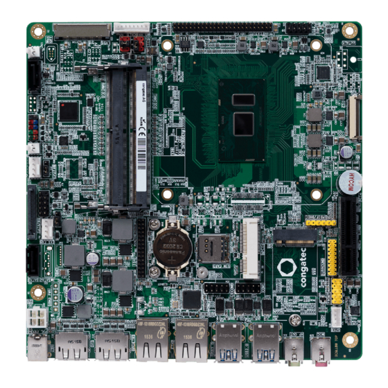
- Page 2 Manual congatec conga-IC175 Mini-ITX Embedded Motherboard with 7. Gen. Intel® Core and Celeron U Processors The information contained in this document has been carefully researched and is, to the best of our knowledge, accurate. However, we assume no liability for any product failures or damages, immediate or consequential, resulting from the use of the information provided herein.
- Page 3 conga-IC175 Thin Mini-ITX SBC Detailed Description Of The congatec Thin Mini-ITX Based On 7th Generation Intel U-Series SoC User's Guide Revision 1.1...
- Page 4 Revision History Revision Date (yyyy-mm-dd) Author Changes 2017-01-18 • Preliminary release 2017-12-05 • Updated section 5.8.1 “Standard SATA Connectors” • Updated table 43 “Feature Connector X38 Pinout Description” • Added content to section 8 “BIOS Setup Description” 2018-08-01 • Updated tables 10 “Power Consumption Values” and 11 “CMOS Battery Power Consumption” in section 2.5 •...
- Page 5 Preface This user's guide provides information about the components, features and connectors available on the conga-IC175 Thin Mini-ITX single board. Disclaimer The information contained within this user’s guide, including but not limited to any product specification, is subject to change without notice. congatec AG provides no warranty with regard to this user’s guide or any other information contained herein and hereby expressly disclaims any implied warranties of merchantability or fitness for any particular purpose with regard to any of the foregoing.
- Page 6 Symbols The following symbols are used in this user's guide: Warning Warnings indicate conditions that, if not observed, can cause personal injury. Caution Cautions warn the user about how to prevent damage to hardware or loss of data. Note Notes call attention to important information that should be observed. Connector Type Describes the connector used on the Single Board Computer.
- Page 7 Trademarks Product names, logos, brands, and other trademarks featured or referred to within this user’s guide, or the congatec website, are the property of their respective trademark holders. These trademark holders are not affiliated with congatec AG, our products, or our website. Warranty congatec AG makes no representation, warranty or guaranty, express or implied regarding the products except its standard form of limited warranty (“Limited Warranty”) per the terms and conditions of the congatec entity, which the product is delivered from.
- Page 8 Technical Support congatec AG technicians and engineers are committed to providing the best possible technical support for our customers so that our products can be easily used and implemented. We request that you first visit our website at www.congatec.com for the latest documentation, utilities and drivers, which have been made available to assist you.
-
Page 9: Table Of Contents
Contents Introduction ................10 5.4.2 LVDS ..................30 5.4.3 Embedded DisplayPort (eDP) ..........32 Mini-ITX Concept ..............10 5.4.3.1 Backlight Power Connector ............. 33 conga-IC175 ................10 5.4.3.2 Backlight/Panel Power Selection ..........33 1.2.1 Options Information ..............11 5.4.3.3 Monitor OFF connector ............34 1.2.2 Optional Accessories ............... - Page 10 congatec Board Controller (cBC) ..........49 6.11 External System Wake Event ........... 52 6.7.1 Fan Control ................49 6.12 Feature Connector ..............52 6.7.2 Power Loss Control ..............50 conga-IC175 Mechanical Drawing ........... 54 6.7.3 Board Information ..............50 Embedded BIOS ..............50 BIOS Setup Description ............
- Page 11 List of Tables Table 1 conga-IC175 Variants ............... 11 Table 37 Connector X11 Pinout Description .......... 47 Table 2 Cooling/IO Shield ..............11 Table 38 Connector X60 Pinout Description .......... 47 Table 3 Cables ..................11 Table 39 ISH (Connector X61) Pinout Description ........48 Table 4 Adapters ..................
-
Page 12: Introduction
Introduction Mini-ITX Concept The Mini-ITX form factor provides enthusiasts and manufacturers with a standardized ultra compact platform for development. With a footprint of 170 mm x 170 mm, this scalable platform promotes the design of highly integrated, energy efficient systems. Due to its small size, the Mini- ITX form factor enables PC appliance designers not only to design attractive low cost devices but also allows them to explore a huge variety of product development options - from compact space-saving designs to fully functional Information Station and Value PC systems. -
Page 13: Options Information
1.2.1 Options Information The conga-IC175 is currently available in four variants. This user’s guide describes all of these variants. The table below show the different configurations available. Check for the part number that applies to your product. This will tell you what options described in this user’s guide are available on your particular module Table 1 conga-IC175 Variants... -
Page 14: Table 4 Adapters
Cables Part No. Description cab-ThinMini-ITX-USB20-Twin 14000123 Dual USB 2.0 cable for congatec Thin Mini-ITX family cab-ThinMini-ITX-LVDS-OE 14000125 LVDS cable with open end for congatec Thin Mini-ITX family. Can be used also for eDP with open end cab-ThinMini-ITX-BKLT 14000127 Backlight cable for congatec Thin Mini-ITX family cab-DP to HDMI Passive 14000128 Passive DisplayPort to HDMI cable... -
Page 15: Specification
Specification Feature List Table 6 Feature Summary Form Factor Based on Thin Mini-ITX form factor (170 x 170 mm) Processor Generation Intel Core™ i7,i5, i3 and Celeron Single Chip Ultra Low TDP Processors ® Memory Two memory sockets (located on the top side of the conga-IC175). Supports SO-DIMM non-ECC DDR4 modules Data rates up to 2133 MT/s Maximum 32 GB capacity (16 GB each) -
Page 16: Supported Operating Systems
Optional Onboard 1x SBM support header 1x SBM power Interfaces 1x CEC header 1x ccTalk Other Features Thermal and voltage monitoring CMOS Battery Beeper congatec standard BIOS (also possible to boot from an external BIOS by triggering the BIOS_DISABLE# signal on the feature connector) BIOS AMI Aptio UEFI 5.x firmware, 8/16 MByte serial SPI with congatec Embedded BIOS features... -
Page 17: Supply Voltage Power
Supply Voltage Power • 12 – 24 V DC ± 5 % Power Consumption The power consumption values were measured using the following test setup: • Input voltage +12 V • conga-IC175 SBC • conga-IC175 cooling solution • Microsoft Windows 10 (64 bit) Note The CPU was stressed to its maximum workload. -
Page 18: Supply Voltage Battery Power
Table 8 Power Consumption Values The tables below provide additional information about the conga-IC175 power consumption. The values are recorded at various operating mode. Part Memory BIOS OS (64 bit) Current (A) Size Rev. Rev. Variant Cores Freq. /Max. Turbo S0: Min S0: Max S0: Peak S3 052900 2 x 4 GB R000 Windows 10... -
Page 19: Environmental Specifications
Environmental Specifications Temperature Operation: 0° to 60°C Storage: -20° to +70°C Humidity Operation: 10% to 90% Storage: 5% to 95% Note The above operating temperatures must be strictly adhered to at all times. Humidity specifications are for non-condensing conditions. Copyright © 2017 congatec AG ICKLm11 17/56... -
Page 20: Block Diagram
Block Diagram M.2 Slot micro-SIM card PCIe x4 (WWAN or SSD) optional PCIe Mini Card DP++ (Full / Half Lenght) DP++ Intel ULT SOC (CPU + PCH) ® 2x Dual USB 2.0 Generation Intel ® Core ™ Processor USB2.0/USB3.0 Flash 4x USB3.0 Turbo Boost 2.0 Technology HT Technology... -
Page 21: Cooling Solution
3. With passive or custom cooling solution, the end user must make sure that adequate air flow is maintained. 4. The congatec conga-IC175 cooling solutions support maximum TDP of 15 W. For applications with higher TDP, you need a custom cooling solution or additional cooling components. -
Page 22: Active Cooling Dimensions
Active Cooling Dimensions M3 screws for attaching cooling solution to retention frame Note To replace the fan, use equivalent fan with similar parameters. Copyright © 2017 congatec AG ICKLm11 20/56... -
Page 23: Cooling Installation
Cooling Installation Assembly Instruction: • Flip over the SBC and locate the position of the CPU • Place retention frame on the bottom side of the board with insulating foil facing the PCB & standoffs inserted to mounting holes in PCB. Make sure the retention frame is placed correctly, without touching surrounding components. -
Page 24: Connector Description
Connector Description Power Supply You can power the conga-IC175 SBC with a 12 V – 24 V laptop type DC power supply (on connector X48) or a 4-pin internal power supply (on connector X49). Additionally, the SBC offers an optional SBM power connector (only BOM option). -
Page 25: Power Supply (Internal Connector)
5.1.2 Power Supply (Internal Connector) The conga-IC175 offers an internal 4-pin power connector. This connector makes it possible to use customized power supply cables or connectors. The power input protects against under voltage or over voltage. Table 12 Connector X49 Pinout Description Internal Power Connector X49 Pin Signal Description... -
Page 26: Optional Sbm3 Signal Connector
Connector Type X47 : 1x5-pin, 3 mm pitch Molex Micro-FIT connector 5.1.3.1 Optional SBM3 Signal Connector For designs that require SBM battery kit, you need the optional power connector X47 and the signal connector X47. The signal connector ensures the conga-IC175 communicates flawlessly with the battery kit. Table 14 Connector X46 Pinout Description SBM3 Signal - Connector X46... -
Page 27: Cmos Battery/Rtc
CMOS Battery/RTC The conga-IC175 provides a board-mounted battery holder (M60) for CMOS battery. The CMOS battery supplies the necessary power required to maintain the CMOS settings and configuration data in the UEFI flash chip. The specified battery type is CR2032 The conga-IC175 offers an optional connector (X44) for external CMOS battery. -
Page 28: Pci Express
PCI Express The conga-IC175 provides 3 PCIe interfaces—a PCIe M.2 slot on connector X10 (see section 5.6.3), a PCIe x4 slot on connector X7 and a full/ half size mini PCIe slot on connector X8. 5.3.1 PCIe x4 Slot The conga-IC175 offers a PCIe x4 slot on connector X7. Table 16 PCIe x4 Slot (Connector X7) Pinout Description Signal... -
Page 29: Full/Half-Size Mini Pcie
PCIE_TX2+ PCIE_TX2- PCIE_RX2+ PCIE_RX2- PCIE_TX3+ PCIE_TX3- PCIE_RX3+ PCIE_RX3- PRSNT#2 RSVD Connector Type X7: PCIe x4 connector 5.3.2 Full/half-size Mini PCIe The conga-IC175 offers a mini PCIe socket on connector X8. This socket is optimized for mobile computing platforms and provides the ability to insert different removable mini PCIe cards. - Page 30 Signal Signal PERn0 +3.3V PERp0 +1.5V SMB_CLK PETn0 SMB_DATA PETp0 USB_D- USB_D+ +3.3V +3.3V LED_WLAN# (optional) CL_CLK CL_DATA +1.5V CL_RST# +3.3V Note The micro-SIM card slot (connector X11) can optionally be connected to these pins (UIM interface). Connector Type X8: PCIe mini card socket Copyright ©...
-
Page 31: Pci Express Routing
5.3.3 PCI Express Routing The diagram below shows how the PCIe lanes are routed to the PCIe connectors. PCIe x4 Slot 0 PCIe Lane1 PCIe Lane2 PCIe Lane3 PCIe Lane4 Mini PCIe Slot 1 PCIe Lane9 USB 2.0 Signals M.2 Connector Slot 2 PCIe Lane11 PCIe Lane12 or SATA port 2... -
Page 32: Display Interfaces
Display Interfaces The conga-IC175 supports up to three independent displays. The interfaces supported are two Digital Display Interfaces and one LVDS or eDP interface. 5.4.1 Display Port Interface DP++ The conga-IC175 SBC has two DP++ connectors (X18 and X19) located at the rear I/O panel. These connectors support DP/HDMI/DVI displays. DP++ Connectors X18/X19 Connector Type X18,X19: Standard DisplayPort connector... -
Page 33: Table 18 Connector X25 Pinout Description
Table 18 Connector X25 Pinout Description Pin Signal Signal LVDS_A3+ LVDS_A3- EDID_3.3V LVDS_A2+ LCD_GND LVDS Connector X25 LVDS_A2- LCD_GND LVDS_A1+ LCD_GND LVDS_A1- LVDS_A_CLK+ LVDS_A0+ LVDS_A_CLK- LVDS_A0- BKLT_GND LVDS_B3+ BKLT_GND LVDS_B3- BKLT_GND LVDS_B2+ EDID_CLK LVDS_B2- eDP_LVDS_BKLT_EN LVDS_B1+ eDP_LVDS_BKLT_CTRL LVDS_B1- LVDS_B_CLK+ LVDS_B0+ LVDS_B_CLK- LVDS_B0- BKLT_PWR... -
Page 34: Embedded Displayport (Edp)
5.4.3 Embedded DisplayPort (eDP) The conga-IC175 provides eDP interface on connector X20 - a standard 40-pin DisplayPort connector. The eDP signals are sourced from incoming eDP stream via a multiplexer. The multiplexer routes the eDP signals to LVDS connector X25 (via an eDP to LVDS bridge) by default. To route the eDP signals to eDP connector X20, change the ‘Active LFP Configuration”... -
Page 35: Backlight Power Connector
5.4.3.1 Backlight Power Connector The conga-IC175 provides backlight power on connector X22. Table 20 Connector X22 Pinout Description Signal Name Description Backlight Power - Connector X22 eDP_LVDS_BKLT_EN Backlight enable eDP_LVDS_BKLT_CTRL Backlight control BKLT_PWR Backlight inverter power BKLT_PWR Backlight inverter power Backlight ground Backlight ground Brightness_Up... -
Page 36: Monitor Off Connector
Table 22 Connector X24 Pinout Description Backlight Voltage Selector - Jumper X24 Jumper Position Backlight Voltage +12 V Pin 2 Pin 6 +5 V Connector Type No Pin No Pin X23, X24: 2.54 mm, 2x3-pin header (without pins 1 and 5) Default Settings: Pin 3 Pins 3 and 4... -
Page 37: Internal Usb Connectors
USB Port 2 USB Port 4 USB Port 1 USB Port 3 Note The +5V signals of connector X13 and X14 have a maximum current of 1 A each. Connector Type X13,X14: Dual USB 3.0 type A (stacked) connector 5.5.2 Internal USB Connectors The conga-IC175 offers four USB ports (ports 7-10) internally. -
Page 38: Sata Interfaces
Table 25 Connector X15 Pinout Description Internal USB - Connector X15 USB Port 9 USB Port 10 Signal Description Signal Description +5 V supply +5 V supply Pin 2 USB9- USB Port 9, Data- USB10- USB Port 10, Data- USB9+ USB Port 9, Data+ USB10+ USB Port 10, Data+... -
Page 39: Sata Power
Note 1. The conga-IC175 offers an additional standard SATA connector (X50) via an assembly option (customized variant). 2. Connector X51 supports eSATA devices. 3. Connector X52 supports SATADOM devices on hardware revision A.x and later. Connector Type X50,X51,X52: Standard SATA connector 5.6.2 SATA Power The conga-IC175 provides an internal SATA power for hard drives on connector X12. -
Page 40: M.2 Slot
5.6.3 M.2 Slot The conga-IC175 offers an M.2, type 3042/2242 slot (X10) for connecting SATA or PCIe x2 SSDs and WWAN devices. Table 27 Connector X10 Pinout Description (Revision B.x and later) M.2 Type B Slot - Connector X10 Pin Signal Pin Signal CONFIG_3 +3.3V... - Page 41 Pin Signal Pin Signal RESET# SUSCLK CONFIG_1 +3.3V +3.3V +3.3V CONFIG_2 Note 1. On hardware revision A.x and earlier, the M.2 slot supports SATA SSD and WWAN (USB 2.0) devices by default, and PCIe x1 devices via a customized BIOS. 2.
-
Page 42: Ethernet
Ethernet The conga-IC175 provides two Gigabit Ethernet ports (connectors X5 and X6) on the rear side. Only the LAN interface on connector X5 supports Intel AMT technology Connector X5/X6 Table 28 LED Description LED Left Side Description LED Right Side Description 10 Mbps link speed No link Green... -
Page 43: Internal Audio Connectors
Table 30 Line-OUT (Connector X31) Pinout Description Line OUT - Connector X31 Jack (Line-IN) Pin Jack Signal Description LINE_L Line-OUT - left channel Ring LINE_R Line-OUT - right channel Ring Sleeve A_GND Analog ground Sleeve Connector Type X29, X31: 3-pin, 3.5 mm single audio jack 5.8.2 Internal Audio Connectors The conga-IC175 provides the stereo speaker, digital microphone/SPDIF, front panel HD and surround audio connectors internally. -
Page 44: Digital Microphone/Spdif
5.8.2.2 Digital Microphone/SPDIF The Digital Microphone/SPDIF signals of the Realtek ALC888S HDA audio codec are routed to the internal digital microphone/SPDIF connector X28. This connector offers two power supply pins (3,3 V and 5 V). Power Budget of these pins is limited to 500 mA. Internal Digital Microphone/SPDIF (Connector X28) Pinout Description Pin Signal Description... -
Page 45: Surround Header
5.8.2.4 Surround header The surround signals of the Realtek ALC888S HDA audio codec are routed to the internal surround connector. Table 33 Surround (Connector X26) Pinout Description Pin Signal Description Pin Signal Description Surround - Connector X26 LINE1_L 1st Analog line input left channel A_GND Analog ground A_GND... -
Page 46: I²C Bus
5.11 I²C Bus The congatec board controller provides I²C signals. These signals are available in different locations on the conga-IC175, including the feature connector (X38) described in section 6.12 of this document. 5.12 LPC Super I/O Device The conga-IC175 has an onboard Super I/O controller. The controller is connected to the SoC’s LPC bus and provides additional interfaces such as two serial interfaces, optional ccTALK, GPOs, 4-wire CPU and system fans. -
Page 47: Cpu/System Fan Connector & Power Configuration
5.12.3 CPU/System Fan Connector & Power Configuration The conga-IC175 supports 5V or 12V CPU and system fans. The signals of the CPU and system fans are routed to connectors X33 and X36 respectively. Use jumper X32 to select the voltage of the CPU fan and jumper X35 to select the voltage of the system fan. Table 35 CPU/SYS Fan Pinout X33/X36 Pin... -
Page 48: Additional Features
Additional Features Front Panel Connector The conga-IC175 SBC supports front panel features such as power button, status LEDs and reset button via connector X39—a 10-pin internal header. The FP_LED+ and FP_LED- signals communicate the system states to two LEDs connected to this header. See section 5.1.4 “Power Status LED”... -
Page 49: Micro-Sim Card
Micro-SIM Card The conga-IC175 offers a micro-SIM slot on connector X11 for inserting SIM card. SIM Slot - Connector X11 Table 37 Connector X11 Pinout Description Signal Description Power Reset Clock Not available Ground Programming voltage input Data Not available Note 1. -
Page 50: Integrated Sensor Hub
Signal Description +3.3V Supply voltage SD_CLK Serial clock Ground SD_D0 Data line (bit 0) SD_D1 Data line (bit 1) Connector Type X60: Micro-SD card slot Integrated Sensor Hub The conga-IC175 offers an Integrated Sensor Hub (ISH) on connector X61. ISH - Connector X61 Table 39 ISH (Connector X61) Pinout Description Pin 1... -
Page 51: Case Open Intrusion Connector
Case Open Intrusion Connector The conga-IC175 provides connector X2 for case-open intrusion detection. Table 40 Case Open Intrusion (Connector X2) Pinout Description Case Open Intrusion - Connector X2 Function INTRUDER# Connector Type X2: 2.54 mm, 2-pin Molex KK series connector Optional TPM The conga-IC175 SBC can be equipped optionally with a TPM 2.0 compliant security chip. -
Page 52: Power Loss Control
6.7.2 Power Loss Control The cBC has full control of the power-up of the SBC and therefore can be used to specify the behavior of the system after an AC power loss condition. Supported modes are “Always On”, “Remain Off” and “Last State”. 6.7.3 Board Information The cBC provides a rich data-set of manufacturing and board information such as serial number, EAN number, hardware and firmware revisions,... -
Page 53: Congatec Battery Management Interface
6.8.3 congatec Battery Management Interface In order to facilitate the development of battery powered mobile systems based on embedded modules, congatec AG defined an interface for the exchange of data between a CPU module (using an ACPI operating system) and a smart battery system. A system developed according to the congatec Battery Management Interface Specification can provide the battery management functions supported by an ACPI-capable operating system (e.g. -
Page 54: External System Wake Event
6.11 External System Wake Event The conga-IC175 supports LAN, USB, PCIe and PWRBTN driven wake up events. 6.12 Feature Connector The conga-IC175 provides an internal 50-pin, 2mm pin header as feature connector. The pinout is described below: Table 41 Feature Connector X38 Pinout Description Feature Connector X38 Pin# Signal Name... - Page 55 GPO6 Output 3.3V PU 4k7 General purpose output from Super IO (LPC) GPO7 Output 3.3V PU 4k7 General purpose output from Super IO (LPC) GPI0 Input 3.3V PU 10k General purpose input to Board controller GPI1 Input 3.3V PU 10k General purpose input to congatec Board controller GPI2 Input...
-
Page 56: Conga-Ic175 Mechanical Drawing
conga-IC175 Mechanical Drawing LVDS BACKLIGHT FEATURE CONNECTOR 2x USB 2.0 HEADER Bklt Power Power SPDIF/DMIC SIM CARD SATA2 SATA1 COM0 COM1 DP++ DP++ ETH1 ETH2 USB3.0 USB3.0 LINE OUT 6.35 23.2 8.06 98.2 104.7 163.83 Copyright © 2017 congatec AG ICKLm11 54/56... -
Page 57: Bios Setup Description
BIOS Setup Description The BIOS setup description of the conga-IC175 can be viewed without having access to the module. However, access to the restricted area of the congatec website is required in order to download the necessary tool (CgMlfViewer) and Menu Layout File (MLF). The MLF contains the BIOS setup description of a particular BIOS revision. -
Page 58: Updating The Bios
Updating the BIOS BIOS updates are recommeded to correct platform issues or enhance the feature set of the module. The conga-IC175 features a congatec/AMI AptioEFI firmware on an onboard flash ROM chip. You can update the firmware with the congatec System Utility. The utility has five versions— UEFI shell, DOS based command line , Win32 command line, Win32 GUI, and Linux version. - Page 59 Our company network supports you worldwide with offices in Germany, Austria, Switzerland, the UK and the USA. For more information please contact: Headquarters Germany FORTEC Elektronik AG Phone: +49 89 894450-0 E-Mail: info@fortecag.de Augsburger Str. 2b Internet: www.fortecag.de 82110 Germering Fortec Group Members Distec GmbH, Phone:...
Need help?
Do you have a question about the congatec conga-IC175 and is the answer not in the manual?
Questions and answers