Table of Contents
Advertisement
Quick Links
Advertisement
Table of Contents

Related Manuals for ALBIN PUMP ALH Series


Summary of Contents for ALBIN PUMP ALH Series
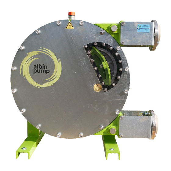
- Page 1 since 1928 ALBIN ALH INSTRUCTION MANUAL...
- Page 2 • The inserts material. • The shoe material. Albin pump cannot guaranty the hose lifetime or the product loss due to a hose burst. It is the operator’s responsibility to prevent pumped liquid loss with additional hose rupture detectors and or automatic shut down valves. Check §2.4 conditions of guarantee for further information.
- Page 3 SECURITY AND GUARANTEES. Safety measures HOW TO USE THIS MAINTENANCE MANUAL. Use of the pump Responsibility Training and instructions Conditions of guarantee DESCRIPTION. 3.1 Product identification 3.2 Operation principle Pump construction Pump hose Pump gearbox 3.6 Electrical Motor Available Options INSTALLATION. Unpacking and control Conditions of installation Setup Piping...
- Page 4 CONDITIONS OF GUARANTEE Albin pump S.A.S offers a guarantee of 2 years on the pump’s parts. Albin pump S.A.S promises to repair or to replace for free all dam- aged parts except if their deterioration came from a poor use of the pump. This concerns all parts except for the hose, the clamps, the sleeves, seals, bushings and bearings as well as the pump shoes.
- Page 5 DESCRIPTION Identification of the pump Albin Pumps are identifiable by the pump plate located on the upper bracket. This one includes the type and serial number of the pump. This serial number leads to all information concerning building materials, nature of the hose, characteristics of the gearbox and characteristics of the motor. The gearbox as well as the motor include their own descriptive plate on which you can read the reduction ratio, power and electrical voltage etc.
- Page 6 PUMP CONSTRUCTION 3.3.1 PUMPS ALH05 to ALH20 PART NO DESIGNATION ALH 05 - 10 - 15 - 20 CASING CAST IRON COVER LEXAN WHEEL CAST IRON SLEEVE EPDM CLAMP ON CASING STAINLESS STEEL CLAMP SLEEVE / HOSE BICHROMATED STEEL CLAMP ON HOSE BICHROMATED STEEL SEAL COVER NITRILE INSERT STAINLESS STEEL LUBRICANT GLYCERIN BLEND HOSE NR/NBR/EPDM BRACKET ELECTROPLATED STEEL STEEL FRAME ELECTROPLATED STEEL COVER FLANGE ELECTROPLATED STEEL...
- Page 7 3.3.1 PUMPS ALH25 to ALH65 PART NO DESIGNATION ALH 25 - 32 - 40 ALHX 40 - 50 - 65 CASING CAST IRON CAST IRON COVER ELECTROPLATED STEEL STEEL WHEEL CAST IRON CAST IRON SHIM GALVANIZED STEEL GALVANIZED STEEL SHOE ALUMINIUM ALUMINIUM (ALHX40) / CAST IRON (ALH50-65) SLEEVE EPDM EPDM CLAMP ON CASING STAINLESS STEEL STAINLESS STEEL CLAMP SLEEVE / HOSE STAINLESS STEEL STAINLESS STEEL...
- Page 8 3.3.1 PUMPS ALHX80 to ALH125 PART NO DESIGNATION ALHX 80 - ALH 80 ALH 100 - ALH 125 CASING CAST IRON CAST IRON COVER STEEL STEEL WHEEL CAST IRON CAST IRON SHIM GALVANIZED STEEL GALVANIZED STEEL SHOE CAST IRON CAST IRON SLEEVE EPDM EPDM CLAMP ON CASING STAINLESS STEEL STAINLESS STEEL CLAMP SLEEVE / HOSE STAINLESS STEEL STAINLESS STEEL CLAMP ON HOSE BICHROMATE STEEL BICHROMATE STEEL...
- Page 9 HOSE The Albin hoses are manufactured according to very strict specifications to acquire the best performances of the pump and to assure an optimum hose life. They are available in three materials: Natural Rubber (NR), perbunan (NBR), EPDM, NBR food and Hypalon. The material of the hose must be compatible with the pumped liquid. Consult an Albin pump distributor to define the best hose for your process or consult the chemical resistance table on our website albinpump.com. HOSE DIMENSIONS (dimensions in mm) PUMP Ø INSIDE THICKNESS LENGTH ALH10 ALH15 ALH20 ALH25 14,5...
- Page 10 During the reception of the pump, please follow the indications pointed out on the packing. Undertake a visual control to be sure that no damage happened during the transport. If this is the case, please contact your Albin pump distributor as soon as possible.
- Page 11 LIFTING THE PUMP Pumps are provided with two lift rings fitted on the upper part of the frame. While lifting the pump, respect the following points: - Lift the complete hose pump using the lifting rings plus additional support on the gearbox and the motor using suitably rated straps or slings. - Never exceed the upper limits of lift and control the motorized pump weights in the table below. - The motorized pump, given its centre of gravity, will tend to overbalance on the pump head side. Make sure that the persons are at a security distance of the pump to avoid any risk of wound.
- Page 12 Remove the sight glass REF15 as well as its seal REF46 and fill the casing with the Albin lubricant (see lubricant table §9.5.). You can REF 23 also fill the casing by the breather cap REF52 situated at the back of the pump casing. The level of necessary lubricant is at the level of the sight glass or underneath the shaft line (see photograph). FOR MODELS ALH05-10-15-20: Unscrew higher plug REF23 of the pump.
- Page 13 HOSE CLEANING The hose cleaning can be done without removing the hose. It can be done with water or with a cleaning liquid (check compatibility with hose material). With numerous products, it is necessary to clean the hose after every pumping in order to avoid the hardening of the product inside this one.
- Page 14 -At the discharge end, loosen clamps REF8 and 9. -Extract the insert REF12 and remove the flange REF47 as well as the brackets REF18 (photograph 4). -Remove clamps REF8 and 9 (photograph 5). REF 47 FOR MODELS ALH05-10-15-20: - At the pump outlet, loosen clamps REF8 and REF9. Remove circlips REF24 and dismantle bracket REF18. REF 12 Extract insert REF12. Remove clamps REF8 and REF9. PHOTO 4 REF 9 REF 8 REF 24 REF 18 REF 12 PHOTO 5 Jog run the motor to deliver the hose from the pump casing at the outlet side. WARNING! The hose can come out of the pump casing very fast and cause harm.
- Page 15 6.3.2 PUMP CASING CLEANING This operation is necessary when a hose has burst and when the product has contaminated the inside of the pump casing. Unscrew cover bolts by leaving two screws partly fastened to the casing. Slightly withdraw the cover from the casing and fix a shackle in one of the cover’s highest fastening holes. (Pumps ALH80, 100 and 125 are equipped with a lifting ring).
- Page 16 Insert the hose by the outlet port (photograph 2). Reverse the direction of rotation of the motor. While pushing on the hose, jog run the motor and check the direction of rotation. PHOTO 2 The shoes mounted on the wheel are going to “swallow” the hose and push it out of the inlet port. Always by giving jolts, bring the hose against the flange REF47 (photograph 3).
- Page 17 REPLACEMENT OF SPARE PARTS 6.4.1 REPLACEMENT OF PUMP SHOES (except ALH05 to ALH20) Jog run the motor and position one of the shoes in front of the sight glass. Cut the power supply. 3. Drain the lubricant (see §6.1). 4. Remove the pump cover REF2 as well as the cover seal REF10. Disassemble the shoe which is not in contact with the hose and put aside the shims if any.
- Page 18 6.4.2 REPLACEMENT OF THE SEAL RING REF27 AND THE SHAFT SEAL REF26 Albin hose pumps are equipped with a leakage channel that allows to see the wear of the seal ring or the shaft seal. This channel is at the back of the pump casing underneath the gearbox flange. It also protects the gearbox seals by leaving the lubricant or the product to pass freely at the back of the pump casing.
- Page 19 13. Mount the gear motor on the casing being careful not to damage the shaft seal. Tighten the nuts REF41 with their washers REF72. 14. Mount the wheel on the pump shaft by positioning it referring to the table and the drawings below. REF 19 PUMP 05 - 10 15 - 20 50 - 65 Distance cas- 4 mm 2,75 mm 5,5 mm 6 mm 2,5 mm 5 mm 3 mm 6,5 mm 8 mm ing / shoe (L) Tolerance 0,5 mm 0,5 mm 0,5 mm 0,5 mm 0,5 mm...
- Page 20 15. Cross tighten the expansible hub with a dynamometric spanner to the torques that figure in the table below. Check the wheel position once again. PUMP TYPE TORQUE Nm ALH05-10-15-20 ALH25-32-40 ALHX40 ALH50-65 ALHX80 ALH80 (shaft Ø90) ALH80 (shaft Ø100) 16. Mount the cover seal REF10 in its groove and mount the cover. 17. Mount the pump hose as stated in §6.3.3. PUMPS ALHX80 to ALH125 (refer to the nomenclature for the landmarks of parts §9.3.) Undertake the same operations 1 to 10 as for pumps ALH05 to ALH65. 2. Disassemble the seal flange REF25 and withdraw the shaft seal with a screwdriver or a similar tool. 3.
- Page 21 SHOE SHIMMING NOTE: This paragraph does not concern pumps ALH05 to ALH20. CAUTION! The shimming of shoes is an operation which consists in adding shims under the shoe to stop any internal leakage. An internal leakage considerably reduces the life time of the hose as well as the flow. As a result, it is essential to adjust the shoe’s shimming according to the rotation speed of the pump, the desired discharge pressure and the liquid viscosity.
- Page 22 MAINTENANCE AND PERIODIC INSPECTIONS ALH and ALHS SERIES. In prevention, change the pump hose after Pump hose replacement. see §6,3 90 % of the life time of the first hose. At the end of two hose changes or 5000 Lubricant replacement. hours of functioning. Otherwise, in every see §6,1 hose break. Refer to the gearbox maintenance manual Gearbox oil replacement.
- Page 23 ALHS SERIES COMPLEMENTARY INFORMATION 6.6.1 SETUP Before the setup of the pump, check the following points: - The ALHS pump is delivered without a frame. Assembly holes are at the back of the pump for assembly on a frame. Dimensions of these assembly holes can be found in § 9.2 l. The pump with its drive and frame must be fixed to a solid base with a slope which does not exceed 5mm for 1m and must be firmly fastened to this one. - The pump frame must be built in order to support the stress and deformations delivered by the pump and drive. It should be built by qualified staff with good engineering practice. In no case ALBIN PUMP AB is reponsable for it’s construction or conception.
- Page 24 TROUBLESHOOTING PROBLEM POSSIBLE REASON RESOLUTION The pump does not work No power supply. Check that the pump power switch is on position “ON”. Check the connection of the motor. The wheel of the pump stalls. Check the fixing of the hose. Check that the discharge pressure is not too high. Check that the product hasn´t sedimentated in the hose.
- Page 25 TROUBLESHOOTING PROBLEM POSSIBLE REASON CORRECTION Hose life is too short. Incompatibility of the hose with the pumped Make sure the compatibility of the hose product. with your product and contact your Albin distributor. Discharge pressure too high. Check that the discharge pressure of the pump does not exceed 15 bars (or 8 bars for ALH05 to ALH20). Check that the outlet piping is not blocked up and that all valves are opened.
- Page 26 CHARACTERISTICS AND TECHNICAL SPECIFICATIONS PERFORMANCE CURVES 0.25 0.55 ALH 05 (3 lobes) ALH 10 (3 lobes) Installed power (Kw) Installed power (Kw) 40°C 40°C 0.18 0.37 50°C 50°C 60°C 60°C 0.12 0.25 70°C 70°C 80°C 80°C Continous 24/24h Intermittent* Occasional* Continous 24/24h Intermittent* Occasional* Pump speed (Rpm)
- Page 27 CHARACTERISTICS AND TECHNICAL SPECIFICATIONS PERFORMANCE CURVES 0.55 ALH 20 ALH 25 Installed power (Kw) Installed power (Kw) 40°C 40°C 0.37 50°C 50°C 60°C 60°C 0.25 70°C 70°C 80°C 80°C Continous 24/24h Intermittent* Occasional* Continous 24/24h Intermittent* Occasional* Pump speed (Rpm) Pump speed (Rpm) Flow (l/h) 1020 Flow (m3/h)
- Page 28 CHARACTERISTICS AND TECHNICAL SPECIFICATIONS PERFORMANCE CURVES ALHX 40 ALH 50 Installed power (Kw) Installed power (Kw) 40°C 50°C 40°C 60°C 50°C 60°C 70°C 70°C 80°C 80°C Continous 24/24h Intermittent* Occasional* Continous 24/24h Intermittent* Occasional* Pump speed (Rpm) Pump speed (Rpm) Flow (m3/h) Flow (m3/h) 1.75 5.25 8.75...
- Page 29 CHARACTERISTICS AND TECHNICAL SPECIFICATIONS PERFORMANCE CURVES 18.5 ALH 80 ALH 100 Installed power (Kw) Installed power (Kw) 40°C 40°C 50°C 50°C 60°C 60°C 70°C 70°C 80°C 80°C Continous 24/24h Intermittent* Occasional* Continous 24/24h Intermittent* Occasional* Pump speed (Rpm) Pump speed (Rpm) Flow (m3/h) 10.5 17.5 24.5...
- Page 30 ALBIN PUMP DIMENSIONS ALH05 to ALH125 FLANGED GEAR MOTOR and ALHS series PUMPS ALH05 to ALH20 3 LOBES 2 LOBES 4 x K * Hose tail ALH05-10 103,5 33,5 ALH15 51,75 ALH20 51,75 ALH05-10 4xø9 46,5 34,5 ø16 * 81,25 ALH15 4xø13...
- Page 31 PUMPS ALH25 to ALH40 4 x K ALH25 355,5 ALH32 122,5 435,5 525,5 157,75 ALH40 122,5 435,5 525,5 157,75 ISO FLANGE ALH25 4xø13 DN25 PN16 ALH32 4xø13 DN32 PN16 157,75 ALH40 4xø13 DN40 PN16 157,75 ALL DIMENSIONS AND TECHNICAL DATA IS SUBJECT TO CHANGE WITHOUT NOTICE...
- Page 32 PUMPS ALHX40 to ALH125 ALHX40 ALH50 164,5 517,5 801,5 186,5 1050 ALH65 164,5 517,5 801,5 186,5 1050 ALHX80 1004 1150 1250 ALH80 1320 1300 1400 ALH100 1040 1680 1900 2000 ALH125 263,5 1273 1038 1750 1000 1140 1900 2000 ISO FLANGE ALHX40 4xø19 DN40 PN16...
- Page 33 PUMPS ALHS05 to ALHS20 Connections SHAFT FRAME O BARB DIAMETER FASTENINGS ALHS05 225,5 81,3 43,5 34,5 ø16mm 33,7 18k6 4xM8 ALHS10 ALHS15 ø20mm 51,5 35,5 87,5 22k6 4xM8 ALHS20 ø25mm ALL DIMENSIONS AND TECHNICAL DATA IS SUBJECT TO CHANGE WITHOUT NOTICE...
- Page 34 PUMPS ALHS25 to ALHS100 PUMP PLATE - PLAQUE DE POMPE Connections SHAFT O ISO FRAME DIAMETER FLANGES FASTENINGS ALHS25 335,5 DN25 PN16 30k6 4xM10 ALHS32 DN32 PN16 435,5 40k6 4xM12 ALHS40 DN40 PN16 ALHSX40 DN40 PN16 40k6 4xM12 ALHS50 DN50 PN16 517,5 97,5 50k6 4xM16 ALHS65 DN65 PN16 ALHSX80...
- Page 35 NOMENCLATURE NOMENCLATURE ALHS05 - ALHS20...
- Page 36 NOMENCLATURE NOMENCLATURE ALH10 - ALH20...
- Page 37 NOMENCLATURE NOMENCLATURE ALH25 - ALH40...
- Page 38 NOMENCLATURE NOMENCLATURE ALHX40 - ALH65...
- Page 39 NOMENCLATURE NOMENCLATURE ALHX80 - ALH80...
- Page 40 NOMENCLATURE NOMENCLATURE ALH100 - ALH125...
- Page 41 NOMENCLATURE NOMENCLATURE ALHS25 - ALHS125...
- Page 42 SPARE PARTS LIST ALH and ALHS series ALH 05 ALH15 ALH25 TO ALHX40 TO REF. DESIGNATION ALHX80 ALH80 ALH100 ALH125 ALH10 ALH20 ALH40 ALH 65 CASING COVER WHEEL SHIM SHOE SLEEVE CLAMP SLEEVE CLAMP ON SLEEVE / HOSE CLAMP ON HOSE COVER SEAL INSERT LUBRICANT SIGHT GLASS HOSE BRACKET BOLT ON PLATE FRAME LIFT RING OIL PLUG CIRCLIPS SEAL FLANGE SHAFT SEAL...
- Page 43 TABLE OF LUBRICATION The table indicates the quantity of lubricant necessary for every pump size. Employ only the Albin lubricant for Albin hose pumps. refer to §6.2 for lubricant emptying and filling. PUMPS ALH 05-10 ALH 15-20 ALH 25 ALH 32 ALH 40 ALHX 40 QUANTITY OF LUBRICANT (LITRES) PUMPS ALH 50 ALH 65 ALHX 80 ALH 80 ALH 100 ALH 125 QUANTITY OF LUBRICANT (LITRES) SHOE SHIMMING TABLE Refer to §6.5 to remove or add shims. The table below points out the necessary number of shims under every...
- Page 44 GENERATED NOISE AND TEMPERATURE NOISE The Albin Pumps do not generate more than 60dB during their operation. TEMPERATURE The cover and the pump casing can become very hot due to the friction on the hose and liquid temperature. If you need to limit the pump temperature, please contact your Albin pump distributor.
-
Page 45: Table Of Contents
Complementary instructions for ATEX certified material Peristaltic hose pump Complementary instructions for ATEX certified material. Models: Albin Pump ALH and ALHS Pumping and operation in zone 0 is completely banned. The pumps are planned for a use in the following gas and dust explosive atmospheres. II 2G: zone 1 and 2 II 3G: zone 1 and 2 II 2D: zone 1 and 2... -
Page 46: Protection Of The Pumping Part
Going beyond these limits is likely to generate a risk of ignition of the atmosphere surrounding the material. The Albin pump installations are in particular designed so that the normal working conditions of the pump do not generate an overload of the motor or the reducer. -
Page 47: Particular Dispositions When Using A Frequency Inverter
Complementary instructions for ATEX certified material 10.4 Particular dispositions when using a frequency inverter The Albin peristaltic pumps have variable limits of working according to the discharge pressure, number of rotations of the pump and temperature of the pumped product. These working limits are mainly imposed by the heating of the hose, on which the lifespan is strongly dependent. -
Page 48: Checking Lubricant Level In The Pump
Complementary instructions for ATEX certified material 10.9 Checking of the lubricant level in the pump An insufficient lubricant level in the pump can generate surface temperatures higher than the recommended limit of temperature T of the pump. Stop the pump and check the lubricant level every 1000 working hours. 10.10 Drive of the pump The maximum speed of rotation of the pumps must be respected (see certification of the pumps). At the start or after any modification of the pumping installation, the speed of rotation of the pump must be controlled and must be lower than the maximum speed indicated in the instructions. -
Page 49: Atex Characteristics Of The Pumping Installation
Complementary instructions for ATEX certified material 10.11 ATEX characteristics of the pumping installation A pumping installation can be composed of materials (motor, reducer, sensors…) from which ATEX characteristics are different from those of the pump. In this case, the group will have ATEX characteristics corresponding to characteristics ATEX of the component with the lowest level of protection. 10.12 Pumping vat of retention At a constant arrival of liquid in a vat of retention in an ATEX zone, the uninterrupted start-up can generate a classification in zone 0. The case can only arise when the pump is used in the starting position. It is then imperative that the suction pipe always has liquid present so as not to create explosive conditions in the presence of fuel and combustive agents.
Need help?
Do you have a question about the ALH Series and is the answer not in the manual?
Questions and answers