HEIDENHAIN ND 780 User Manual
Hide thumbs
Also See for ND 780:
- Operating instructions manual (261 pages) ,
- Installation instruction (132 pages) ,
- Quick reference manual (88 pages)

Related Manuals for HEIDENHAIN ND 780


Summary of Contents for HEIDENHAIN ND 780
- Page 1 SALES & SERVICE: A Tech Authority, Inc. 13745 Stockton Ave. Chino CA 91710 909-614-4522 sales@atechauthority.com User’s Manual ND 780 English (en) 8/2006...
- Page 2 Soft keys - Row of keys under the screen of Up/Down arrow keys - Clear key select entry field the ND 780 whose functions vary according are also used to adjust to associated fields that appear above them screen contrast...
- Page 3 ND 780 Back View KT 130 Edge Finder Ground (Protective Earthing) Grounding Edge finder Serial port Power button Main power input Axis ports...
- Page 5 Caution - Risk of electric shock e.g. when opening a housing. The ND 780 and the machine tool must be prepared by the machine tool builder to perform this function. ND 780 Fonts...
-
Page 7: Table Of Contents
Incremental Workpiece Positions ..13 Zero Angle Reference Axis ..14 Position Encoders ..14 Encoder Reference Marks ..15 I – 2 General Operations for ND 780 ..16 Layout of Screen ..16 General Navigation ..17 Operating Modes ..17 Graphic Positioning Aid .. - Page 8 I – 3 Milling Specific Operations ..33 Soft Key Functions Detailed ..33 Tool Soft Key ..33 Tool Radius Compensation feature ..33 Tool Table ..33 Tool Table Usage ..35 Calling the Tool Table ..37 Tool call ..
- Page 9 Diagnostics ..81 Keypad Test ..81 Encoder signal plot ..81 II – 3 Encoder Parameters ..82 Example settings for HEIDENHAIN linear encoders with 11-µA signals ..82 Example settings for HEIDENHAIN linear encoders with 1-V signals ..82 II –...
- Page 10 II – 8 Dimensions ..96 II – 9 Accessories ..97 Accessory ID Numbers ..97 ND 780 Handle Id. Nr. 520 012-01 ..97 ND 780 Mounting Instructions Universal Mounting Arm ld. Nr. 382 929-01 ..98 ND 780 Mounting Instructions Tilting Base ld.
-
Page 11: I Operating Instructions
Operating Instructions ND 780... -
Page 12: I - 1 Fundamentals Of Positioning
I – 1 Fundamentals of Positioning Datums The workpiece drawing identifies a certain point on the workpiece (usually a corner) as the absolute datum and perhaps one or more other points as relative datums. The datum setting procedure establishes these points as the origin of the absolute or relative coordinate systems. -
Page 13: Absolute Workpiece Positions
IY = 10 mm IZ = –15 mm Fig. I.3 Position 3 using incremental coordinates If you are drilling or milling a workpiece according to a drawing with incremental coordinates, you are moving the tool by the value of the coordinates. ND 780... -
Page 14: Zero Angle Reference Axis
If there is an interruption in power, the calculated position will no longer correspond to the actual position. When power is restored, you can re-establish this relationship with the aid of the reference marks on the position encoders and the ND 780’s reference mark evaluation feature (REF). Fig. I.5... -
Page 15: Encoder Reference Marks
Encoders with distance-coded reference marks have marks separated by a specific encryption pattern that allows the ND 780 to use any two pair of marks along the length of the encoder to re- establish the prior datums. -
Page 16: General Operations For Nd 780
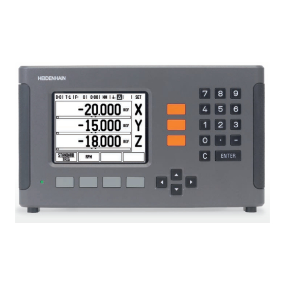
I – 2 General Operations for ND 780 Layout of Screen Status Bar Symbols Datum Tool Feed Rate Stopwatch Unit of Actual Value Distance- Page Set/Zero Measure To-Go Indicator Axis Labels Display Area Ref Symbols Graphic Soft key Positionin Labels... -
Page 17: General Navigation
“distance-to-go” required to get to the desired nominal position relative to the edge of the tool that will be doing the cutting. If the ND 780 is configured for a lathe, all tool offsets are used in both the Actual Value and Distance-To-Go modes. -
Page 18: Graphic Positioning Aid
Graphic Positioning Aid When you are traversing to display value zero (in the Distance-To-Go mode), ND 780 displays a graphic positioning aid. See Fig. I.8. ND 780 displays the graphic positioning aid in a narrow rectangle underneath the currently active axis. Two triangular marks in the center of the rectangle symbolize the nominal position you want to reach. -
Page 19: Error Messages
Fig. I.10 Example of Form and Instruction Box Error Messages If an error occurs while you are working with ND 780, the message will appear on the display and provide an explanation of what caused the error. -
Page 20: Power Up
Installation Setup under Counter Settings. Fig. I.11 Initial screen Your ND 780 is now ready for operation and is in the operating mode Actual Value. Each active axis will have a flashing“REF”sign next to it. At this point the reference mark evaluation should be completed. -
Page 21: Enable/Disable Ref Function
NO REF soft key to cancel out of routine. You do not have to cross over the reference marks of all the encoders, only those that you need. If all reference marks have been found the ND 780 will return to the DRO display screen automatically. -
Page 22: Setup
Setup ND 780 offers two categories for setting up operating parameters. These categories are: Job Setup and Installation Setup. The Job Setup parameters are used to accommodate specific machining requirements for each job. Installation Setup is used to establish encoder, display and communication parameters. -
Page 23: Scale Factor
The diameter must be greater than zero. The length is a sign value (negative or positive). A soft key is provided to indicate the units of measure for the edge finder. The edge finder values will be retained on a power cycle. ND 780... -
Page 24: Diameter Axes
Output of the current display positions is activated via an external hardware signal or via a command (Ctrl B) sent to ND 780 over the Fig. I.15 Diameter Axes form serial port. -
Page 25: Graphic Positioning Aid
The Status Bar is the segmented bar at the top of the screen which displays current datum, tool, feed rate, stop watch and page indicator. Press the ON/OFF soft key for each setting you want to see displayed. Fig. I.16 Graphic positioning aid ND 780... -
Page 26: Stopwatch
Stopwatch The stopwatch shows the hours (h), minutes (m), seconds (s). It operates like a stop watch showing elapsed time. (The watch starts timing from 0:00:00). The elapsed time field shows the total accumulated time from each interval. Press the START/STOP soft key. The status field will read RUNNING. Press it again to stop time from elapsing. -
Page 27: Console Adjustment
120 minutes. The display saver can be disabled during the current power cycle. Language The ND 780 supports multiple languages. To change the language selection: Press the LANGUAGE soft key until the desired language selection appears on the soft key and the form. -
Page 28: General Operation's Soft Key Function Overview
General Operation’s Soft Key Function Overview There are three pages of soft key functions to select from. Use the LEFT/RIGHT ARROW keys to cursor through each page. The page indicator in the Status bar will show the page orientation. The darkened page indicates the page you are currently on. -
Page 29: General Operation's Soft Key Functions Detailed
Set and Zero. The current state is indicated in the Status Bar. When the state is Set, and the ND 780 is in Actual Value mode, selecting an Axis key opens the DATUM form for the selected axis. If the ND 780 is in Distance-To-Go mode, a PRESET form opens. -
Page 30: Calc Soft Key
If you were to enter 3 + 1 ÷ 8, ND 780 will divide one by eight, then add three for an answer of 3.125. - Page 31 The table may be consulted for a recommended range of surface speeds for the material being machined. Press the UNITS soft key to show the units as inch or millimeter. The RPM CALCULATOR form is closed by pressing the C key. ND 780...
- Page 32 Taper Calculator Soft Key (Turning Applications only) You can calculate tapers either by entering dimensions from a print, or by touching a tapered workpiece with a tool or indicator. Use the taper calculator to calculate taper angle. See Fig. I.22 and Fig I.23.
-
Page 33: I - 3 Milling Specific Operations
You can enter up to 16 tools. See Fig. I.25. The length offset may be entered as a known value or the ND 780 may determine the offset automatically. See the following Tool Table Usage example for more information regarding the TEACH LENGTH soft key. - Page 34 Sign for the length difference ΔL If the tool is longer than the reference tool: ΔL > 0 (+) If the tool is shorter than the reference tool: ΔL < 0 (–) The tool length is the difference in length ΔL between the tool and the reference tool.
-
Page 35: Tool Table Usage
Tool diameter 2.00 Tool length: 20.000 Tool unit: mm Tool type: flat end mill It is also possible to have ND 780 determine the length of an offset. See alternative example below. Fig. I.27 Tool length and diameter entry ND 780... - Page 36 Enter the tool length for example, (20 mm) and cursor down to the UNITS field. - ALTERNATIVE METHOD - It is also possible to have ND 780 determine an offset. This method involves touching the tip of each tool to a common reference surface. This allows ND 780 to determine the difference between the length of each tool.
-
Page 37: Calling The Tool Table
ENTER. Calling the Tool Table Before you start machining, select the tool you are using from the tool table. ND 780 then takes into account the stored tool data when you work with tool compensation. Tool call Press the TOOL soft key. -
Page 38: Datum Soft Key
Datum settings define the relationships between the axis positions and the display values. The easiest way to set datum points is to use the ND 780’s probing functions – regardless of whether you probe the workpiece with an edge finder or a tool. - Page 39 DOWN ARROW key to advance to the Y-axis. Touch the workpiece at edge 2. DATUM SETTING Y Enter the position of the tool center (Y = – 1.5 mm) Fig. I.30 press the DOWN ARROW key. Touch the workpiece surface. ND 780...
-
Page 40: Probing Functions For Datum Setting
Probing Functions for Datum Setting It is particularly easy with a HEIDENHAIN Electronic 3D, KT 130 Edge Finder (Fig. I.31) connected through X10. The ND 780 also supports a grounding type edge finder connected via the 3.5 mm Phono Jack on the back of the unit. - Page 41 DOWN ARROW key. Fig. I.33 Press EDGE soft key. PROBE IN Y AXIS Move the edge finder toward the workpiece until the LEDs on the edge finder light up. Retract the edge finder from the workpiece. ND 780...
- Page 42 ENTER VALUE FOR Y + 0 0 is offered as a default value for the coordinate. Enter the desired coordinate for the workpiece edge, for this example Y = 0 mm and set the coordinate as a datum for this workpiece. Press ENTER.
- Page 43 ENTER CENTER POINT X X = 50 Enter the first coordinate (X = 50 mm) and press the DOWN ARROW key. ENTER CENTER POINT Y Y = 0 Fig. I.37 Accept default entry Y = 0 mm. Press ENTER. ND 780...
-
Page 44: Probing With A Tool
Even if you use a tool or non-electrical edge finder to set datum points, you can still use ND 780’s probing functions. See Fig. I.38 & Fig. I.39. Preparation: Set the active tool to the tool that will be used to set the... - Page 45 (T:1, 2...) and the last direction the tool was moved prior to pressing the NOTE soft key. Retract the tool from the workpiece. ENTER VALUE FOR X Enter coordinate of the edge press ENTER. ND 780...
-
Page 46: Preset Soft Key
Preset Soft Key The Preset function allows the operator to indicate the nominal (target) position for the next move. Once the new nominal position information is entered the display will switch to Distance-To-Go mode and show the distance between the current position and the nominal position. - Page 47 Press the PRESET soft key. Press the X axis key - ALTERNATIVE METHOD - Press the SET/ZERO soft key so that you are in Set mode. Press the X axis key. ND 780...
- Page 48 NOMINAL POSITION VALUE Enter nominal position value for corner point 2: X = +30 mm, select tool radius compensation R – with R+/- soft key. Press twice until R- is shown next to axis form. Press ENTER. Traverse the X axis until the display value is zero. The square in the graphic positioning aid is now centered between the two triangular marks.
- Page 49 X = +60 mm, select tool radius compensation R + and press ENTER. Traverse the X axis until the display value is zero. The square in the graphic positioning aid is now centered between the two triangular marks. ND 780...
- Page 50 Incremental Distance Preset Example: Drilling by traversing to display value zero with incremental positioning Enter the coordinates in incremental dimensions. These are indicated in the following (and on the screen) with a preceding I. The datum is the workpiece zero. See Fig. I.43 & Fig. I.44. Hole at: X = 20 mm / Y = 20 mm Distance from hole...
- Page 51 Press ENTER. Traverse the X and Y axes until the display value is zero. The square in the graphic positioning aid is now centered between the two triangular marks. Press the PRESET soft key. Press the Z axis key. ND 780...
-
Page 52: 1/2 Soft Key
NOMINAL POSITION VALUE Press ENTER (uses last entered preset). Drill hole 2: Traverse Z axis until the display value is zero. The square in the graphic positioning aid is now centered between the two triangular marks. Retract the drill. 1/2 Soft Key The 1/2 soft key is used to find the half-way (or midpoint) between two locations along a selected axis of a workpiece. -
Page 53: Patterns Soft Key (Milling)
(e.g. hole depth, number of holes, etc.). With hole patterns, the ND 780 then calculates the positions of all the holes and displays the pattern graphically on the screen. The View Graphic enables verification of the hole pattern before you start machining. - Page 54 Example: Enter data and execute a circle pattern. See Fig. I.46, Fig. I.47 & Fig. I.48. Holes (no. of): 4 Coordinates of center: X = 10 mm / Y = 15 mm Bolt circle radius: 5 mm Start angle: (Angle between X axis and 1st hole): 25° Hole depth: Z = -5mm 1st step: Enter data Press PATTERN soft key.
- Page 55 Traverse to display value zero in the tool axis. After drilling, retract the drill in tool axis. Press the NEXT HOLE soft key. Continue to drill the remaining holes in the same way. When pattern is complete, press the END soft key. ND 780...
-
Page 56: Linear Pattern
Linear Pattern Information required: „ Linear pattern type (array or frame) „ First hole (1st hole of the pattern) „ Holes per row (number of holes in each row of pattern) „ Hole spacing (the spacing or offset between each hole in the row) „... - Page 57 Fig. I.50 Linear Pattern Form HOLES PER ROW Enter the number of holes per row (4).Cursor to the next field. HOLE SPACING Enter the hole spacing (10). ANGLE Enter the tilt angle (18°). Fig. I.51 View of Linear Pattern Graphic ND 780...
- Page 58 DEPTH Enter the depth when needed (-2). The depth of the hole is optional and may be left blank. NUMBER OF ROWS Enter the number of rows (3). ROW SPACING Enter the spacing between rows, press ENTER. Pressing the VIEW soft key to see the graphic. 2nd step: Drill Move to hole: Traverse the X and Y axes until display value zero.
-
Page 59: I - 4 Turning Specific Operations
Tool Soft Key The ND 780 can store the dimensional offsets for up to 16 tools. When you change a workpiece and establish a new datum, all tools are automatically referenced from the new datum. -
Page 60: Tool Table Usage
Select the axis (X) key. Enter the position of the tool tip, for example, X=Ø 20 mm. Remember to ensure the ND 780 is in diameter Fig. I.53 display mode (Ø) if you input a diameter value. Touch the workpiece face with the tool. -
Page 61: Setting Tool Offset Using Note/Set Function
Turn the spindle off and measure the workpiece diameter. Fig. I.55 TOOL/SET Form Enter the measured diameter or radius, for example, 15 mm and press ENTER. Remember to ensure the ND 780 is in diameter display mode (Ø) if you input a diameter value. ND 780... -
Page 62: Datum Soft Key
Datum Soft Key See "Datum Soft Key" on page 38 for basic information. Datum settings define the relationships between the axis positions and the display values. For most lathe operations there is only one X-axis datum, the center of the chuck, but it may be helpful to define additional datums for the Z-axis. - Page 63 DATUM SETTING X Enter the diameter of the workpiece at that point. Remember to ensure the ND 780 is in diameter display mode (Ø) if you input a diameter value. Press the DOWN ARROW key to advance to the Z-axis.
-
Page 64: Setting Datums Using Note/Set Function
Turn the spindle off and measure the workpiece diameter. Enter the measured diameter, for example, 15 mm and press ENTER. Remember to ensure the ND 780 is in diameter display mode (Ø) if you input a diameter value. Fig. I.59 Setting Datum using NOTE/SET I Operating Instructions... -
Page 65: Preset Soft Key
(see below). (Radius/Diameter) Soft Key Drawings for lathe parts usually give diameter values. ND 780 can display either the radius or the diameter for you. When the diameter is being displayed, the diameter symbol (Ø) is shown next to the position value. -
Page 67: Technical Information
Technical Information... -
Page 68: Installation And Electrical Connection
Locate the unit in a well ventilated area such that it may be easily accessed during normal operation. Installation M4 screws are used to secure ND 780 from below. For the hole locations: See "Dimensions" on page 96. Electrical connection There are no serviceable items within this unit. -
Page 69: Electrical Requirements
Minimum cross-section of the connecting wire: 6 mm , see Fig. II.2. Preventative maintenance No special preventative maintenance is necessary. For cleaning, wipe lightly with a dry lint-free cloth. Fig. II.2 The protective conductor terminal on the rear panel. ND 780... -
Page 70: Connecting The Encoders
Connecting the Encoders ND 780 can be used with HEIDENHAIN linear and rotary encoders that provide sinusoidal output (11µA or 1V ). The encoder inputs on the rear panel are designated X1, X2 and X3. See Fig. II.3 & Fig. II.4. - Page 71 The operator can setup any encoder input to go to any axis. Default configuration: Encoder input Mill Turn Fig. II.4 Encoder inputs on rear panel. ND 780...
-
Page 72: Connecting Edge Finder Output And Input Signals
Connecting Edge Finder Output and Input Signals Connect the HEIDENHAIN Edge Finder to the D-sub input X10 on the rear panel. Adapt ND 780 for use with the Edge Finder through the following operating parameters: „ Stylus length „ Stylus diameter For description of operating parameters, see "Job Setup Parameters"... -
Page 73: Ii - 2 Installation Setup
For this reason, the installation setup parameters are protected by a passcode: (95148) type these digits in using the numeric key pad and then press ENTER. Fig. II.8 Installation screen ND 780... -
Page 74: Encoder Setup
Encoder Setup Encoder Setup is used to set the encoder resolution and type (linear, rotary), count direction, reference mark type. See Fig. II.9. The cursor will default to the ENCODER SETUP field upon opening Installation Setup. Press ENTER. This opens a list of 3 possible encoders, labelled INPUT X1 X2 or X3. -
Page 75: Z Coupling (Turning Applications Only)
Z Coupling (turning applications only) The ND 780 Turning application provides a quick method for coupling the Z and Z axis position on a 3 axis system. The display can be coupled in either the Z or Z displays. See Fig. II.10. -
Page 76: Error Compensation
You can determine these errors with a reference measurement system, e.g. the VM 101 from HEIDENHAIN or with gauge blocks. From an analysis of the error it can be determined which form of compensation is required, linear or non-linear error. -
Page 77: Non-Linear Error Compensation
The required correction values are calculated and entered in a table. ND 780 supports up to 200 points per axis. The error value between two entered adjacent correction points is calculated with linear interpolation. -
Page 78: Backlash Compensation
Viewing the Compensation Table Press the EDIT TABLE soft key. To switch between the table and graph views, press the VIEW soft key. Press the UP or DOWN ARROW keys or the numeric keys to move the cursor within the table. The error compensation table data may be saved to or loaded from a PC via the serial port. -
Page 79: Serial Port (X31)
Refer to Data Interface section for cable connection and pin assignments. Data is transferred in the following sequence: Start bit, Seven data bits, Parity bit (even parity), Two stop bits. ND 780... -
Page 80: Counter Settings
Counter Settings The COUNTER SETTINGS form is the parameter where the operator defines the user application for the readout. The choices are for milling or turning applications. See Fig. II.16. A FACTORY DEFAULT soft key appears in the COUNTER SETTINGS choice of options. -
Page 81: Diagnostics
Select which encoder you want to observe. Cursor to the desired input and press ENTER. As the encoder is moved you will see the signals of the A & B channels. Fig. II.18 Example of a signal plot ND 780... -
Page 82: Ii - 3 Encoder Parameters
The following tables represent a partial list of encoders. These tables describe all operating parameters which you must set for the encoders. Most entries can be found in the operating instructions for your encoder. Example settings for HEIDENHAIN linear encoders with 11-µA signals Encoder Signal period... - Page 83 Example settings for HEIDENHAIN rotary encoders Encoder Line count Reference marks ROD 250, RON 255 9 000/18 000 ROD 250C, RON 255C 9 000 ROD 250C, ROD 255C 18 000 1 000 ROD 700C, RON 705C RON 706C ROD 700C, ROD 800C...
-
Page 84: Ii - 4 Data Interface
Data which can be exported from the ND 780 to an external serial device includes: „... -
Page 85: Serial Port
ND 780 and the PC is in ASCII text format. To export data from the ND 780 to a PC, the PC must first be made ready to receive the data to save it to a file. Setup the terminal communication program to capture ASCII text data from the COM port to a file on the PC. -
Page 86: Wiring The Connecting Cable
The wiring of the connecting cable depends on the device being connected (see technical documentation for external device). Full wiring Before the ND 780 and your PC can communicate, they need to be connected to each other with a serial cable. See Fig. II.20 & Fig. II.21. Pin assignment... -
Page 87: External Operations Via Rs-232 Data Interface
<ESC>T0117<CR> Key ‘Soft key 4’ <ESC>T0135<CR> Key ‘Cursor Left’ <ESC>T0136<CR> Key ‘Cursor Right’ <ESC>T0137<CR> Key ‘Cursor Up’ <ESC>T0138<CR> Key ‘Cursor Down’ <ESC>A0000<CR> Send device identification <ESC>A0200<CR> Send actual position <ESC>S0000<CR> Reset device <ESC>S0001<CR> Lock keyboard <ESC>S0002<CR> Release keyboard ND 780... -
Page 88: Ii - 5 Measured Value Output
II – 5 Measured Value Output Examples of character output at the data interface If you have a PC you can retrieve values from ND 780. In all three examples, measured value output is started with Ctrl B (sent over serial interface) or a switching signal at the EXT input (within optional Auxiliary Machine Interface). - Page 89 Coordinate axis Equal sign +/– sign 3 to 8 places degrees Colon 0 to 2 places minutes Colon 0 to 2 places seconds Blank space W for angle (in distance-to-go display: w) Carriage return Blank line (Line Feed) ND 780...
-
Page 90: Data Output Using Edge Finder
Data output using Edge Finder In the next three examples, measured value output is started with a switching signal from the edge finder. Printing capability can be turned on or off in the Job Setup parameter Measured Value Output. Information from here is transmitted from the selected axis. Example 4: Probing function Edge Y = –3674.4498 mm 3 6 7 4 4 4 9 8... - Page 91 2 to 7 places before the decimal point Decimal point 1 to 6 places after the decimal point Unit: blank space for mm, " for inches R for radius display, D for diameter display Carriage return Blank line (Line Feed) ND 780...
- Page 92 Example 6: Probing function Circle Center First center point coordinate, e.g. CCX = –1616.3429 mm, Second center point coordinate, e.g. CCY = +4362.9876 mm, (Circle Center X axis, Circle Center Y axis; coordinates depend on working plane) Circle diameter DIA = 1250.0500 mm 1 6 1 6 3 4 2 9 <CR>...
-
Page 93: Ii - 6 Specifications For Milling
II – 6 Specifications for Milling ND 780 Data Axes Up to 3 axes from A - Z Encoder inputs Sinusoidal signals 11 µA , 1 V ; input frequency max. 100 kHz for incremental HEIDENHAIN encoders „ Signal period: 2 µm, 4 µm, 10 µm, 20 µm, 40 µm, 100 µm, 10 240 µm, 12 800 µm... - Page 94 ND 780 Data „ Accessories Tilting Base „ Universal Mounting Arm „ KT 130 Edge Finder „ Tilting Bracket Assembly „ Handle „ Mounting Frame Main power input 100 V to 240 V; 50 Hz to 60 Hz; power consumption 30 VA max.
-
Page 95: Ii - 7 Specifications For Turning
II – 7 Specifications for Turning ND 780 Data Axes Up to 3 axes from A to Z, Z Encoder inputs Sinusoidal signals 11 µA , 1 V ; input frequency max. 100 kHz for incremental HEIDENHAIN encoders „ Signal period: 2 µm, 4 µm, 10 µm, 20 µm, 40 µm, 100 µm, 10 240 µm, 12 800 µm... -
Page 96: Ii - 8 Dimensions
II – 8 Dimensions Dimensions mm/inches Back view Front view with Dimensions Bottom view with Dimensions II Technical Information... -
Page 97: Ii - 9 Accessories
II – 9 Accessories Accessory ID Numbers ID Number Accessories 520010-01 Pkgd, ND 780 382929-01 Pkgd, Universal Mounting Arm, ND 780 281619-01 Pkgd, Tilting Base ND 780 520011-01 Pkgd, Tilting Bracket Assembly ND 780 520012-01 Pkgd, Handle ND 780 283273-01... -
Page 98: Nd 780 Mounting Instructions Universal Mounting Arm
ND 780 Mounting Instructions Universal Mounting Arm ld. Nr. 382 929-01 HHCS 5/8-11 x 3“ SCSS 5/8-2“ x 1/2-13 x .8“ HHCS m16 x 75 mm HHCS m14 x 75 mm 5/8“ Flat Washer (2) M6 x 12 mm M6 x 12 mm SHSS (4) -
Page 99: Nd 780 Mounting Instructions Tilting Base
ND 780 Mounting Instructions Tilting Base ld. Nr. 281 619-01 M4 x 12 SHCS Tilting Base ND 780... -
Page 100: Nd 780 Mounting Instructions Tilting Bracket Ld. Nr. 520011-01
ND 780 Mounting Instructions Tilting Bracket ld. Nr. 520011-01 M8 x 60 HHCS Tilting bracket M6 BHCS II Technical Information... -
Page 101: Nd 780 Mounting Instructions Mounting Frame Ld. Nr. 532811-01
ND 780 Mounting Instructions Mounting Frame ld. Nr. 532811-01 M3.5 ND 780... - Page 103 Probe workpiece edge as datum ... 41 Disable Ref soft key ... 21 Protective Earthing (Grounding) ... 69 Display Area ... 16 Job Setup menu ... 22 Display configuration ... 74 Job Setup Parameters ... 22 distance-coded reference marks ... 15 ND 780...
- Page 104 Radius/Diameter display ... 65 Taper calculator ... 32 REF ... 14 Tool call ... 37 Ref Symbols ... 16 Tool data entering ... 34 Reference Mark Evaluation ... 20 Tool setting, turning ... 60 Reference marks ... 15 Tool soft key ... 33 crossing over ...
- Page 105 SALES & SERVICE: A Tech Authority, Inc. 13745 Stockton Ave. Chino CA 91710 909-614-4522 sales@atechauthority.com Ve 01 532 852-91 · 3 · 8/2006 · FP&D · Printed in USA · Änderungen vorbehalten (Subject to change without notice)
Need help?
Do you have a question about the ND 780 and is the answer not in the manual?
Questions and answers