
Related Manuals for Ahlborn ALMEMO 2590-9 V5


Summary of Contents for Ahlborn ALMEMO 2590-9 V5
- Page 1 Operating Instructions Data Logger ® ALMEMO 2590-9 V2.0 26.06.2003 ® ALMEMO 2590-9...
-
Page 2: Operating Controls
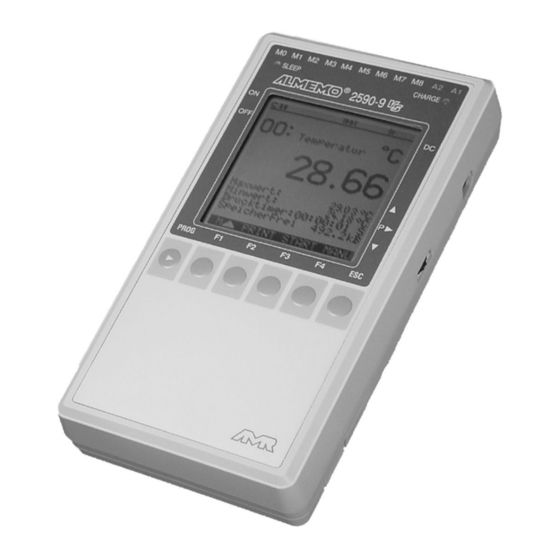
Operating Controls Operating Controls (1) ON/OFF switch down (2) Meas. inputs M0 to M8 M0 ... M8 for all ALMEMO sensors M10...M38 27 additional channels (3) Output sockets A1, A2 A1 Interface V24 (ZA 1909-DK) Fiber optics V24 (ZA 1909-DKL) C!REC COM |>... -
Page 3: Table Of Contents
Table of Contents Operating Instructions Data Logger ALMEMO ® 2590-9 ® For reference with the ALMEMO Manual Table of Contents Page OPERATING CONTROLS INTRODUCTION Function Range INITIAL OPERATION POWER SUPPLY Battery Operation and Supply Voltage Control Mains Operation External DC Voltage Supply Switch On/Off, Reinitialisation Data Buffering CONNECTION OF THE TRANSDUCERS... - Page 4 Table of Contents Page 6.2.3 Print Cycle, Timer, Output Format 6.2.4 Displaying Measured Values as a Line Chart 6.2.5 Continuous Output/Storage of all Measuring Points 6.2.6 Memory Space, Memory Output, Clearing the Memory Correction of the Measured Value and Compensation 6.3.1 Setting the Measured Value to Zero 6.3.2...
- Page 5 Table of Contents Page SENSOR PROGRAMMING Selecting the Input Channel Measuring Point Designation Averaging Mode Locking of the Sensor Programming Limit Values Scaling, Decimal Point Setting Correction Values Changing the Dimension Selecting the Measuring Range 9.10 Special Functions 9.10.1 Print Cycle Factor 9.10.2 Minimum Sensor Supply Voltage 9.10.3 Limit Value Responses, Relay Allocation 9.10.4 Analog Output Start/End...
-
Page 6: Introduction
2590-9 is a new instrument from the unique ® product range of measuring devices that are all equipped with the ALMEMO connector system, which has been patented by Ahlborn GmbH. The intelligent ® ALMEMO connector provides important advantages with regard to the connection of sensors and peripherals as all parameters are stored in an EEPROM within the connector. - Page 7 Function Range Measuring Ranges There are corresponding measuring ranges for sensors with a non-linear characteristic such as 10 thermocouple types, Ntc and Pt100 sensors, infrared sensors, and flow sensors (rotating vanes, thermoanemometers, pitot tubes). Humidity sensors are available with function channels that also calculate humidity data such as dew point, mixture ratio, vapour pressure and enthalpy.
- Page 8 Function Range Limit Values and Alarm Two limit values (1 max and 1 min) can be set for each meas. channel. An alarm value printout can be performed if a limit value is exceeded and, by means of relay output modules, alarm contacts are provided that can be individually allocated to limit values.
- Page 9 Function Range A manual averaging over a particular period or over single measurements is available for the selected channel. PROCESS FLOW PROGRAMMING A cyclic measuring point scan with a time-based process flow control is required to register the measuring data of all connected sensors. For this purpose, the real time clock, the print cycle and the measuring cycle are available and, if fast processing is required, the conversion rate is available.
- Page 10 Function Range saved with each change of the configuration. The output can be carried out via the display or the interface. It is possible to specify a selection according to a time interval, number or alarm value. Numbering of Measurements By entering a number, single scans or entire series of measurements can be identified and selectively read out from the memory.
-
Page 11: Initial Operation
Initial Operation 2. INITIAL OPERATION Connect transducers to the sockets M0 to M8 (2), s. 4. Sensor connection Power supply Internal battery or mains adapter, see 3.1, 3.2 Switch-on Move the left slide switch (1) upwards, see 3.4 Displaying meas. data Keys Call up the main menu ´ALMEMO 2590-9´... -
Page 12: Power Supply
Power Supply 3. POWER SUPPLY The following options are available for the power supply of the instrument: NiCd batt. pack 7.2V built-in or supplement. batt.pack ZB 2590-AP Mains supply unit or battery charger 12V/800mA ZB 2590-NA Electr. isol. power supply cable (10..30V DC, 1A) ZB 2590-UK Our product line includes corresponding accessories. -
Page 13: External Dc Voltage Supply
Connection of the Transducers 3.3 External DC Voltage Supply It is also possible to connect another DC voltage, 12V ±5% (800mA), to the socket DC (5). The connection is performed by using a low voltage connector (NES1 according to DIN 42323), center pin to minus. However, the electrically isolated supply cable ZB 2590-UK must be used if an electrical isolation between power supply and transducers is required or if a larger input voltage range 10...30V is required. -
Page 14: Connection Of The Transducers
Connection of the Transducers 4. CONNECTION OF THE TRANSDUCERS ® ® Any ALMEMO sensors can be connected to the ALMEMO input sockets M0 to M8 of the measuring instrument (2). For connecting existing sensors it is ® only necessary to connect a corresponding ALMEMO connector. - Page 15 Connection of the Transducers The 9 analog inputs are electrically isolated by using photovoltaic relays and a potential difference of 50V DC or 60V AC, at maximum, is permissible between them. However, sensors combined within one connector and sensors with an own power supply are electrically connected to each other and must, therefore, be operated in isolation.
-
Page 16: Display And Keypad
Display and Keypad 5. DISPLAY AND KEYPAD 5.1 Display and Menu Selection The display (6) of the measuring instrument ALMEMO 2590-9 consists of a dot matrix LCD display with 128x128 dots, or 16 lines with 21 characters each, respectively. 11 standard menus and 3 user-definable ´user menus´ U1, U2, U3 are available and can be selected at the main menu for the acquisition of measuring data in connection with the required functions and for the programming of the process control, the sensors and the device parameters. -
Page 17: Function Keys
Display and Keypad 5.2 Function Keys |> >| " C! REC COM The function of the keys F1 to F4 can be °C Temperature different in the various menus. It is M ¯ H -1254.5 indicated by abbreviations in the bottom ▲... -
Page 18: Function Selection
Display and Keypad 5.4 Function Selection |> >| C! REC COM Each menu consists of a number of °C functions that, possibly, have to be used Temperature Temperatur or programmed during operation. 1254 Max Value: 245.7°C Min Value: 224.1°C ▼ PrintTimer: 00:00:00nS MemoryFree: 0211.0kB... -
Page 19: Locking Of The Menus And The Keypad
Display and Keypad ▲ ▼ The function keys indicate, e.g. the symbols: ▲ Increasing the selected number with < >... ▼ Decreasing the selected number < >... Changing the sign of numerical values <+/ > Clearing the programmed values <CLR> PROG! Selecting the next position PrintCycle: 00:00:00... - Page 20 Display and Keypad Locking of the menu access The menus are configured in a hierarchical ALMEMO 2590-9 form and their locking level is indicated at Locked: M0T0 ---- the first digit. The first line provides the StandardDisplay M StandardDispl function ´Locked: MxTx´ for locking of 9 S1 DataLogger 8 S2 LineChart menus and keys.
-
Page 21: Measuring Using The Measurement Menus
Displaying a Measuring Point 6. MEASURING USING THE MEAS. MENUS ® The ALMEMO 2590-9 provides the following options for the data acquisition: Output to the display: Exclusive measurement of the selected measuring point, see manual 6.4 Output of measuring data to the analog output, see manual 5.1.1 Continuous meas. -
Page 22: Display Of A Measuring Point
Displaying a Measuring Point 6.1 Display of a Measuring Point Different from previous instruments, the continuous measuring point scan (e.g. after a reinitialisation, see 3.4) is the standard default setting of the ALMEMO 2590-9, i.e. all meas. points are continuously acquired and the meas. values can be retrieved at any time, even if they are related to other channels (e.g. -
Page 23: Output Of Menu Functions
Displaying a Measuring Point If the cleared channel is also the selected measuring channel, the current measured value will be immediately displayed after the clearing process. Furthermore, the peak values are cleared at each start of a measurement, if the device has been correspondingly configured (standard setting, see 10.8). 6.1.3 Output of Menu Functions Each data menu, together with all displayed functions, can be output via interface to a printer or computer (connection of peripheral devices, see... -
Page 24: Cyclic Output/Storage Of All Measuring Points
Displaying a Measuring Point 6.2.2 Cyclic Output/Storage of all Measuring Points The print cycle (see 7.2) must be programmed for cyclic outputs of measured values (see man. 6.5.1.2) and recording. The measurement can be started using the key <START> and stopped using the key <STOP>. At each start of a measurement the max, min and average values of all meas.points are cleared, if the device has been correspondingly configured (standard setting, see 10.8). -
Page 25: Continuous Output/Storage Of All Measuring Points
Displaying a Measuring Point with indicating and overwriting all measured values at the conversion rate from left to right. The functions ´Analog Start´ and ´Analog End´ of the menu ´Special Functions´ can be used to set the display range of the y axis (see 9.10.4). They can be directly called up using the key ´SCALE´. -
Page 26: Correction Of The Measured Value And Compensation
Displaying a Measuring Point 6.3 Correction of the Meas. Value and Compensation achieve maximum accuracy |> >| " C! REC COM measurements it is possible to correct all Meas.Correction sensors with regard to zero point and slope 24.5ms (gain) in the ´Standard Menu´, by the push of a button. -
Page 27: Setpoint Entry
Displaying a Measuring Point Function ´Zero Point Adjustment´ using the key:: <ADJ> °C 00.0 Meas.Val: ZeroPoint: 23.4°C Zero Point: If a base value has been programmed, the measured value indi- cated after adjustment is not zero but the negative base value. In the case of dynamic pressure probes the zero-point error is writ- ten temporarily (i.e. -
Page 28: Temperature Compensation
Displaying a Measuring Point 6.3.4 Temperature Compensation Sensors with measured values that are strongly depending on the temperature of the measuring medium are, in most cases, equipped with a specific temperature sensor and the instrument will automatically perform a temperature compensation (see sensor list, manual 3. ´TC´).However, dynamic pressure probes and pH probes are also available without a temperature sensor. -
Page 29: Averaging
Displaying a Measuring Point 6.4 Averaging The average value of the measured value is required for various applications: e.g. Smoothing of a largely varying measured value (wind, pressure etc.). The average flow velocity in a ventilating channel. Hourly or daily average values of weather data (temp., wind etc.). As above, of consumption values (current, water, gas etc.). -
Page 30: Averaging Mode
Displaying a Measuring Point 6.4.2 Averaging Mode A detailed description of averaging over measuring point scans is given in the manual section 6.7.4. The type of averaging is determined through the function ® ´Averaging Mode´. If a sensor with an ALMEMO connector is connected the following modes can be set (see 5.5): Averag.Mode: -----... -
Page 31: Averaging Over Cyclic Measuring Point Scans
Displaying a Measuring Point 6.4.4 Averaging over Cyclic Measuring Point Scans Continuous averaging Again, the averaging mode ´CONT´ must be used if the average value over the whole measurement is only required at the end of cyclic meas. point scans. Σ... -
Page 32: Averaging Over Time
Displaying a Measuring Point 6.4.5 Averaging over Time To acquire the average value of all meas. values over a defined period without cycle, the averaging mode ´STSTP´ must be set for the selected measuring channel. For example, by uniformly scanning an area, this mode also allows to determine the average flow velocity in a ventilating channel (see manual 3.5.5). -
Page 33: Volume Flow Measurement
Displaying a Measuring Point 6.4.7 Volume Flow Measurement |> >| " C! REC COM To calculate the volume flow in a flow conduit 01: +11.37ms Velocity extra functions ´Diameter´, ´Cross Section´ ´Volume´ available. 05.00 S220 ms 15.00 Together with the averaging functions they MeasTime: 00:01:23 are organised in the menu ´Flow´, which can... -
Page 34: Display Of Several Measuring Points
Displaying Several Measuring Points 6.5 Display of Several Measuring Points The first three measurement menus allow, on principle, only the selection and display of one measuring point. This chapter provides a description on how you can get up to four measuring points with your selection of functions, or even up to 20 measuring points simultaneously on the display. -
Page 35: Menu Meas. Point List
Displaying Several Measuring Points 6.5.2 Menu List of Measured Values |> >| C! REC COM MeasValList: Name The best overview of the meas. system 12:34:56 01.02.00 incl. all meas. points, time of day, date, 00:00:00 S P: 00:12:34 meas.cycle and print cycle is obtained with 23.12°C Temperat. -
Page 36: Configuration Of User Menus
Configuration of User Menus 6.6 Configuration of User Menus When studying the measurement menus you may have noticed that the display of the measured value and the combination of functions does not always match ® your applications in an optimum way. Therefore, the ALMEMO 2590-9 allows you to freely configure three individual user menus, U1 to U3, in addition to the three standard menus, S1 to S3. - Page 37 Configuration of User Menus Command: Functions: Display: Keys: Graphic (see 6.2.4) TIME SCALE o 35 80%H Humidity 16.33 full screen 20%H 00:10 Averag.Mode: CONT o 18 Averaging mode (s. 6.4.2) ConvRate: 10 Cont: o 19 Conversion rate: (s. 7.4) " PrintTimer:00:00:00nU FORM o 20...
- Page 38 Configuration of User Menus Activate the user menus U1 to U3 by using the key: <S/U> Select the user menu U1, U2 (for one measuring point only) or U3 (for max. 4 meas. points), which <F▲> / <F▼>, PROG suits your application best. Then, the easiest way to configure the menu is to use a Devices PC and the drag and drop function of the AMR-Control...
-
Page 39: Function Printouts
DIAMETER: 01: 00100 mm Diameter CROSSSECTION: 01: 00078 cm2 Cross section VOLUME: 01: 00000 m3/h Volume flow ATMPRESS: 01: +01013.mb Atm. pressure TempComp: 25.0°C Temp. compensation Setpoint: 01: 1100.0°C Setpoint Fa.Ahlborn,Holzkirchen Device designation Line ----------------------------- Blank line CommentText 1 Text1 ® ALMEMO 2590-9... -
Page 40: Configuration Via Interface
Configuration of User Menus Function Printout CommentText 2 Text2 MenuTitle U1 Text3 MenuTitle U2 Text4 MenuTitle U3 Text5 Locking: Locking 6.6.2 Programming via the Serial Interface Only new commands, which are not covered by the manual section 6, will be listed in the following. -
Page 41: Times And Cycles
Times and Cycles 7. Times and Cycles Some time functions for the process Times-Cycles control have been introduced. 12:34:56 01.02.00 PrintCycle: 00:00:00 associated functions are combined in the Storing:- Sleep: - menu ´Times-Cycles´ and can also be Output Format:List programmed there. Meas.Cycle: 00:12:34 Storing:-... -
Page 42: Measuring Cycle And Storage Activation
Times and Cycles Store: Sleep:- Function ´Storage Activation´ in print cycle: " Switch on storing: <ON> Switch off storing: <OFF> If, when using Win-Control to record a measured value, you want the data also saved on the device itself, you should activate the memory during the measuring cycle - because saving during the print cycle is automatically deactivated. -
Page 43: Time And Date Of Start, Time And Date Of End
Times and Cycles Measuring rate function : for input (see Sec.5.5) Measuring rate : Continuous measuring point scan (basic setting) : Cont : " Save : - Continuous storage : <ON> " Activate continuous storage : Output : - Continuous output : <ON>... -
Page 44: Data Memory
Data Memory 8. Data Memory ® The basic information with regard to data storage in ALMEMO devices is given in the manual section 6.9. A new feature is the possibility of saving several measuring operations with dif- ferent configurations; however, to use this facility the ring memory mode must not be set;... -
Page 45: Data Acquisition
Data Memory 8.2 Data Acquisition The parameters, which are required for the recording of measuring data, have already been described in the menu ´Times-Cycles´ (see section 7). . 1. Time and date 2. Print cycle with storage activation, sleep mode, see 8.6 3. -
Page 46: Numbering Of Measurements
Data Memory 8.3 Numbering of Measurements For the identification of measurements or series of measurements it is possible to individually enter a number before starting. It will be used automatically (see above) if the configuration has changed. With the next measuring point scan it will be output or stored, respectively. -
Page 47: Memory Output
Data Memory 8.5 Memory Output The content of the data memory can, completely or in parts, be output to the serial interface. For each output one of the three available output formats ´List´, ´Columns´ or ´Table´ can be used. The option to specify partial ranges is available as it is possible to set the start and end time of measurements and also possible to select the number of corresponding identified measurements. -
Page 48: Sleep Mode
Data Memory Cancelling the memory output using the key: <STOP> Interrupting the memory output using the key: The following options are available after an output interruption: <MANU> Recall individual measured values: <START> Re-start the automatic output: Cancelling the memory output using the key: After the memory output the device returns to the menu ´Memory´. - Page 49 Data Memory The following steps must be carried out in the menu ´TIMES-CYCLES´ to perform a data recording in the true sleep mode: MeasCycle: 00:00:00 1. Clear the measuring cycle: 2. Switch off the continuous measuring point scan: ConvRate: 10 Cont: - PrintCycle: 00:05:00 Enter a print cycle with a min.
-
Page 50: Sensor Programming
Sensor Programming 9. SENSOR PROGRAMMING ® As all ALMEMO instruments contain the whole sensor programming stored in ® the ALMEMO connector plug, the user, usually, does not need to perform any programming. Only if, for example, sensor errors must be corrected or existing sensors must be scaled or limit values need to be specified the comprehensive programming options have to be used. -
Page 51: Measuring Point Designation
Sensor Programming 9.2 Measuring Point Designation Each measuring point can be given a 10-digit alphanumeric designation to optimally identify the type of sensor, the measuring location or the purpose of the application. This comment will be indicated with all standard displays of measured values. -
Page 52: Limit Values
Sensor Programming 9.5 Limit Values Two limit values (MAX, MIN) can be programmed and allocated to each measuring channel. An exceeding of limit values is handled as a fault, similar to an exceeding of meas. range limits and sensor breakage. On the display a corresponding arrow ▲... -
Page 53: Correction Values
Sensor Programming 9.7 Correction Values The correction values ZERO POINT and SLOPE (GAIN) allow for correcting sensors with regard to zero point and slope (gain) (see manual 6.3.10). . Corrected Meas. Value = (Meas.Value - ZERO POINT) x SLOPE (GAIN) Function: ZeroPoint: -----°C... - Page 54 Sensor Programming Transducer Conn./Cable/ Meas. Range Dim Display Sensor P104 ZA 9000-FS -200.0... +850.0 °C Pt100-1 P204 Pt100-2 ZA 9000-FS -200.00...+400.00 °C P104 Pt1000-1 (element flag 1) ZA 9000-FS -200.0... +850.0 °C P204 Pt1000-2 (element flag 1) ZA 9000-FS -200.00...+400.00 °C N104 Ni100...
- Page 55 Sensor Programming Transducer Conn./Cable/ Meas. Range Dim Display Sensor L890 Dyn. press. 90 m/s wth TC a. PC FD A612-M6 1.00... 90.00 ° FH A646 0.0... 100.0 Rel. humidity cap. HcrH Rel. humidity cap. wth TC FH A646-C 0.0... 100.0 H rH Rel.
-
Page 56: Special Functions
Special Functions 9.10 Special Functions The data logger 2590-9 has a separate * SPECIAL FUNCTIONS * ® Connector:0 Chann.:00 menu allowing access to all ALMEMO PrintCycleFactor: special functions, which despite only rarely U-Sensor Min: 12.0 V being required during routine operation, are Action Max: Start R1 very useful for some applications (see... -
Page 57: Limit Value Responses Relay Allocation
Special Functions 9.10.3 Limit Value Responses Relay Allocation As standard, both limit values of all measuring points of a device or of a measuring circuit board are used for fault alarms (see 9.5), i.e. if an exceeding of a limit value occurs at any measuring point, the relay 0 responds if an alarm relay cable or the corresponding relay adapter (see manual 5.2/3) is used. -
Page 58: Analog Output Start/End
Special Functions 9.10.4 Analog Output Start and End In most cases the analog output of measured values to the analog output modules (see manual 5) or the display as bar or line chart must be scaled to a specified sub-range. For this, it is just necessary to specify the start and end value of the display range required by you. -
Page 59: Reference Channel
Special Functions 9.10.6 Reference Channel 1 The arithmetic functions of the function channels, generally, refer to a particular measuring channel (or 2 meas. channels) (see manual 6.3.4). During the programming of a function channel the first channel of the corresponding sensor connector Mxx1 is automatically set as reference channel Mb1. -
Page 60: Device Configuration
The function ´Device Designation´ (see manual 6.2.4) allows to enter any text with max 21 digits (see 5.5). The text appears in the main menu, in the print header of a measurement and in device lists (software). Function ´Device Designation´: Device Designation: Ahlborn,Holzkirchen 10.2 Device Address and Networking ® All ALMEMO... -
Page 61: Baud Rate, Data Format
Device Configuration 10.3 Baud Rate, Data Format All interface modules are factory-set and programmed to 9600 baud. To avoid unnecessary problems when networking several devices the baud rate should not be modified but the computer or printer should be set up accordingly. If this is not possible the values 300, 600, 1200, 2400, 4800, 9600bd, or 57.6, 115.2 kbd can be entered in the function ´Baud Rate´... -
Page 62: Operating Parameter
Output Modules 10.8 Operating Parameters Some operating parameters are software options and can be user-configured with the function ´Config´ (see manual 6.10.13.2). Config: F------- Mains frequency noise suppression 60Hz instead of 50Hz Config: -C------ Clearing all measured values on start of a measurement Config: --R----- Ring memory (overwriting of old data when full) - Page 63 Output Modules Under the prevailing socket the menu indicates: Socket A1: DC DataCable Variant 0: Standard interface always active 0: RS232 Variant 1: Activation in case of addressing 1: RS485 11.2 Relay Trigger Cable The combined input and output cables (ZA 1000-EAK) and the relay trigger analog adapter ZA 800x-RTA (see manual 5.1.2/3) provide max.
- Page 64 Output Modules 11.3 ANALOG OUTPUT For analog acquisition of the selected measuring point either an analog output cable ZA 1601-RK (see manual 5.1.1) without electrical isolation or a relay trigger analog adapter ZA 8000-RTA (see manual 5.1.3) with electrically isolated analog output can be connected to the sockets A1 or A2. Scaling It is possible to spread any partial range to the standard output signal of the three available options 0-2V, 0-10V, 0/4-20mA if the partial range covers at...
-
Page 65: Troubleshooting
Troubleshooting 12. TROUBLESHOOTING ® The data logger ALMEMO 2590-9 can be configured and programmed in many different ways. It allows for a connection of many different sensors, additional measuring instruments, alarm signalisers and peripheral devices. Due to the large variety of options it is possible that, under certain conditions, it does not perform as the user would expect. -
Page 66: Electromagnetic Compatibility
Electromagnetic Compatibility Test the data transmission by using a terminal (AMR-Control, WIN-Control, DATA-Control, WINDOWS Terminal): Select output channel interface U by using the command ´A1´. Address the device with its device number ´Gxy´ (see manual 6.2.1), if the computer is in XOFF state, enter <Strg Q> for XON, query the programming through ´P15´... -
Page 67: Technical Data
Appendix Technical Data ® (see also section 2.2 in ALMEMO Manual) Measuring inputs: ® ® 9 ALMEMO sockets for ALMEMO flat connectors Meas. channels: 9 primary channels electr. isol., max. 27 add. chann. for double sensors and function channels Analog/digital converter delta-sigma 16bit, up to 50 measuring operat. -
Page 68: Keyword Index
Keyword Index Keyword Index Keyword Chapter Page dditional channels Alarm cable, configuration 11.2 Analog output, scaling, channel selection 11.3 Analog output, control via interface 11.3 Analog output, start and end of range 9.10.4 Atmospheric pressure 10.6 Atmospheric pressure compensation 6.3.4 Attenuation of meas. - Page 69 Keyword Index Keyword Chapter Page Device address 10.2 Device designation 10.1 Device configuration Display Display of several measuring points Display of measured values as line chart 6.2.4 Display options for measured values Display, illumination 10.5 Display, contrast 10.5 Displaying a measuring point lectromagnetic compatibility Element flags 9.10.8...
- Page 70 Keyword Index Keyword Chapter Page Measuring point designation Measuring cycle, storage activation Memory output and clearing 6.2.6 Memory output Memory display Memory space 6.2.6 Menu configuration Menu selection Menu, ´Memory´ Menu, ´Sensor Programming´ Menu, ´Device Configuration´ Menu, ´Line Chart´ 6.2.4 Menu, ´Meas.
- Page 71 Keyword Index Keyword Chapter Page Relay triggering 11.2 Relay allocation 9.10.3 Reset 11.3 caling, analog output, line chart Scaling, measured value Selecting the measuring range Selecting the measuring point 6.1.1 Selecting the input channel Sensor programming Sensor supply voltage 9.10.2 Setpoint entry 6.3.2 Setting the measured value to zero...
- Page 72 Appendix ® ALMEMO 2590-9...
Need help?
Do you have a question about the ALMEMO 2590-9 V5 and is the answer not in the manual?
Questions and answers