
Related Manuals for Ahlborn ALMEMO 3290-8 V5


Summary of Contents for Ahlborn ALMEMO 3290-8 V5
- Page 1 Operating Instructions Data Logger ® ALMEMO 3290-8 V2.0 13.07.2000 AHLBORN Mess- und Regelungstechnik GmbH Eichenfeldstraße 1-3 · D-83607 Holzkirchen Tel. +49(0)8024/30070 · Fax +49(0)8024/300710...
-
Page 2: Table Of Contents
Table of Contents Operating Instructions Data Logger ® ALMEMO 3290-8 ® For reference with the ALMEMO Manual Table of Contents Page INTRODUCTION Function Range Front Operating Controls Rear Operating Controls INITIAL OPERATION POWER SUPPLY Mains Supply Operation with Rechargeable Battery (Option A) External Power Supply Switch On/Off, Reinitialisation Data Buffer... - Page 3 Table of Contents Page Limit Values Correction Values, Sensor Adjustment Scaling, Decimal Point Setting Locking the Programming of the Sensor MEASUREMENT Continuous Measurement of a Measuring Point 7.1.1 Selecting the Measuring Point 7.1.2 Memory for Peak Values 7.1.3 Setting the Measured Value to Zero, Zero Point Correction 7.1.4 Atmospheric Pressure Compensation Single Measuring Point Scan...
-
Page 4: Introduction
® ALMEMO connector system, which has been patented by Ahlborn GmbH. The ® intelligent ALMEMO connector provides important advantages with regard to the connection of sensors and peripherals as all parameters are stored in an EEPROM within the connector. - Page 5 Functions Measuring Ranges There are corresponding measuring ranges for sensors with a non-linear characteristic such as 10 thermocouple types, Ntc and Pt100 sensors, infrared sensors, and flow sensors (rotating vanes, thermoanemometers, pitot tubes). Humidity sensors are available with function channels that also calculate humidity data such as dew point, mixture ratio, vapour pressure and enthalpy.
- Page 6 Functions Limit Values and Alarm Two limit values (1 max and 1 min) can be set for each measuring channel. An alarm value printout can be performed if a limit value is exceeded and, by means of relay output modules, alarm contacts are provided that can be individually allocated to limit values.
- Page 7 Functions PROCESS FLOW PROGRAMMING A cyclic measuring point scan with a time-based process flow control is required to register the measuring data of all connected sensors. For this purpose, the real time clock, the print cycle and the measuring cycle are available and, if fast processing is required, the conversion rate is available.
- Page 8 Front Operating Controls Numbering of Measurements Single scans or entire series of measurements can be identified and selectively read out from the memory. Control Outputs The interface allows to individually trigger up to four output relays and one analogue output. Keyboard Lock The keyboard operation can be locked with a password.
-
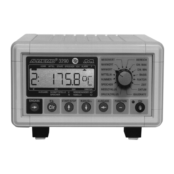
Page 9: Front Operating Controls
Front Operating Controls 1.2 Front Operating Controls 1 9:6 4.2 3 4 m (1) LCD DISPLAY 6½ x 7segment, 2 x 16segment Measured value: meas. channel, meas. value, dimension above -19999 decimal point switch over Exceed. of range: max/min value flashes Exceed. - Page 10 Front Operating Controls (3) FUNCTION SELECTOR SWITCH Function Additional functions Abbrev. MEAS. VALUE NUMBER deactivate increase MAX VALUE analogue output-end MIN VALUE analogue output-start AVERAGE V averaging mode number of aver. values RANGE, UNIT locking mode locking code LV MAX action Hi start/stop LV MIN action Lo start/stop...
-
Page 11: Rear Operating Controls
Rear Operating Controls 1.3 Rear Operating Controls (5) MEASURING INPUTS ® M0 to M9 for all sensors with an ALMEMO connector M10 to M18/M38 additional channels for double sensors and function channels (6) OUTPUTS RS232 interface cable (ZA 1909-DK), RS232 fiber optic cable (ZA 1909-DKL) RS 422 network branch box (ZA 5099-NVB) Centronics interface cable (ZA 1936-DK) A1 or A2... -
Page 12: Initial Operation
Initial Operation 2. INITIAL OPERATION 1. Connect transducers to the sockets M0 to M8 (5), see 4. 2. Ensure power supply by mains adapter connected to socket (7), see 3.1 3. For switching on set the push button (4) so the control lamp is on, s. 3.4. 4. -
Page 13: Power Supply
Power Supply 3. POWER SUPPLY 3.1 Mains Operation In general, the mains adapter ZB 5090-NA2 (12V DC, 800mA) is used for the power supply to the instrument. It is connected to the socket U-DC (7) and is locked by turning it to the right. 3.2 Operation with Rechargeable Battery (Option A) With the option A, a 7.2V NiCd rechargeable battery with 1.5 Ah will be installed, which allows, at a current consumption of approximately 15mA, an... -
Page 14: Data Buffer
Connection of the Transducers The device can be switched off by operating the push button once again. The red control lamp will no longer be illuminated. However, the real time clock continues operating and, due to the buffering rechargeable battery, all stored values remain available (see 3.5). -
Page 15: Measuring Inputs And Additional Channels
Connection of the Transducers 4.2 Measuring Inputs and Additional Channels ® The measuring instrument ALMEMO 3290-8 has 9 input sockets (5) that the ® measuring channels M0 to M8 are initially allocated to. However, ALMEMO sensors can, if required, provide up to 4 channels so that 36 channels are available with 9 input sockets. -
Page 16: Display And Keyboard
Display and Keyboard 5. DISPLAY AND KEYBOARD 5.1 Display and Function Selection ® The display of the measuring device ALMEMO 3290-8 consists of an LCD module with six and a half 7-segment digits, two 16-segment digits, and a battery symbol and seven arrows for indicating the operating status. The basic functions are set by the function selector switch (3). -
Page 17: Keyboard
Display and Keyboard Special Operating Conditions Segment test of the display automatically after switch-on. Supply voltage: lower than 7V: symbol illuminated 1:L o b A t lower than 6V: Sensors that are not connected, deactivated measuring points, 1: - - - - cleared programming values. -
Page 18: Data Input
Display and Keyboard 5.3 Data Entry The programming of numeric parameters is performed as follows: The desired function can be selected using the rotary switch (3) FUNCTION Additional functions, if required, are selected with key FUNCTION. The programming is started by the key ENTER, ENTER The first digit flashes and can be altered. -
Page 19: Sensor Programming
Sensor Programming FUNCTION FUNCTION Selecting the Function Locking Code: RANGE O P E N If the locking is switched off, the display indicates: To lock the access a four digit number C L O S E d is entered (see 5.3) and the display indicates: The functions ENTER, START/STOP and OUTPUT are no longer available in this operating stage. -
Page 20: Selecting The Measuring Range
Sensor Programming 6.2 Selecting the Measuring Range If users want to program the connectors on their own or frequently change the measuring range, it is necessary that the locking is cleared (see 6.7) and special connectors may be required for some transducers (e.g. thermo, shunt, divider etc., see table). - Page 21 Sensor Programming Transducer Conn. / Cable Meas. Range Dim. Display Millivolt 2 ZA 9000-FS -260.00...+260.00 U260 Volt ZA 9000-FS -2.6000...+2.6000 U2.60 Differential-Millivolt 1 ZA 9050-FS -26.000...+26.000 d 26 Differential-Millivolt ZA 9050-FS -10.000...+55.000 d 55 d260 Differential-Millivolt 2 ZA 9050-FS -260.00...+260.00 Differential-Volt ZA 9050-FS -2.6000...+2.6000...
- Page 22 Sensor Programming Transducer Conn. / Cable Meas. Range Dim. Display Function Channels diFF Difference Maximum value Minimum value A[t] Average value over time A[n] Averag. val. over junctions S[n] Sum over junctions S[t] Total number of pulses ZA 9909-AK2 0 ... 65000 S[P] Pulses/print cycle ZA 9909-AK2...
-
Page 23: Changing The Dimension
Sensor Programming 6.3 Changing the Dimension Each measuring channel allows to replace the standard dimension of the measuring range by any other dimension that has two digits (see manual , Ω, %, [, 6.3.5). In addition to all capital and normal letters, the characters ], *, -, =, ~ and spaces (_) are available. -
Page 24: Correction Values, Sensor Adjustment
Sensor Programming 6.5 Correction Values The correction values ZERO POINT and SLOPE allow for correcting sensors with regard to zero point and slope (see manual 6.3.10). Corrected Meas. Value = (Meas. Value - ZERO POINT) x SLOPE. Function: FUNCTION Zero point correct. (ZC) BASE Key:... -
Page 25: Scaling, Decimal Point Setting
Sensor Programming 6.6 Scaling, Decimal Point Setting For indicating the electrical signal of a sensor as a measured value of a physical variable it is, in most cases, necessary to set a zero point shift and to perform a multiplication with a certain factor. The functions BASE and FACTOR are available for this. -
Page 26: Locking The Programming Of The Sensor
Sensor Programming 6.7 Locking the Programming of the Sensor (man. 6.3.12) The function parameters of each measuring point are protected by the locking mode up to an adjustable locking level. Before any programming is performed the locking mode must be correspondingly lowered. If a dot is indicated following the locking mode on the display then a modification is not possible. -
Page 27: Measurement
Continuous Measurement of a Measuring Point 7. MEASUREMENT The instrument ALMEMO ® 3290-8 provides the following options for the acquisition of measuring data: 1. Continuous measurement of a selectable measuring point, see manual 6.4. 2. Single measuring point scan, see manual 6.5.1.1. 3. -
Page 28: Memory For Peak Values
Continuous Measurement of a Measuring Point 7.1.2 Memory for Peak Values From the acquired measured values of each measuring point the highest and lowest value is determined and stored. For indicating the peak values the function MAX. VAL. or MIN. VAL. must be selected with the rotary switch and the desired channel must be set. - Page 29 Continuous Measurement of a Measuring Point Zero Point Adjustment Many sensors must be adjusted at least once or at regular intervals to compensate for instabilities. For this purpose, a specific zero point adjustment is available, in addition to the ´Set Measured Value to Zero´ mentioned above, as some sensors require an additional scaling (e.g.
-
Page 30: Atmospheric Pressure Compensation
Single Measuring Point Scan 7.1.4 Atmospheric Pressure Compensation Some measuring variables depend on the environmental atmospheric pressure (see 6.2 measuring range list ´w. PC´). As a result, higher deviations from the normal pressure of 1013mbar can cause corresponding measuring errors: e.g. -
Page 31: Print Cycle, Output Channel, Output Format
Cyclic Measuring Point Scan 7.3 Cyclic Measuring Point Scan (see manual 6.5.1.2) For cyclic measuring point scans the measuring or print cycle (see 7.3.1/2) must be programmed. The measurement is started with the key START/STOP and the arrow ´START´ is continuously indicated. If the memory is active (see 7.4.1) the measured values are stored and the arrow ´MEMORY´... -
Page 32: Measuring Cycle And Memory Activation
Cyclic Measuring Point Scan Output formats (see manual 6.6.1) The output format determines the print output at measuring point scans and at the memory output. Apart from the standard list format, with all measured values given in a list, the column output format allows for a clear and space-saving printout in columns. -
Page 33: Time And Date
Cyclic Measuring Point Scan 7.3.3 Conversion Rate, Continuous Measuring Point Scan If required the conversion rate can be increased from 2.5 to 10M/sec (see manual 6.5, 6.5.4). The rotary switch must be moved to position MEAS. CYCLE and the additional function CONVERSION RATE ´CR´ must be selected by using the key F and must be set by using the keys ENTER, , ENTER. -
Page 34: Start And Stop By Limit Values
Cyclic Measuring Point Scan 7.3.5 Time and Date of Start, Time and Date of End A sequence of measurements can, at certain points in time, be automatically started and stopped. For this purpose, the time and date of the start and the time and date of the end can be programmed. - Page 35 Data Memory An averaging process for the measured values of measuring point scans can be programmed for each measuring point (manual 6.7.4). The average value can be indicated and programmed at switch setting AVG VAL. Average values must be cleared before each measurement and for programming. The clearing of an average value is performed after selecting the input channel by using the keys ENTER, Clr or by a total clearing (see 7.).
-
Page 36: Data Memory
Data Memory 7.4 Data Memory ® The basic information with regard to data storage in ALMEMO devices is given in the manual section 6.9. The memory organisation can be reconfigured from linear to ring memory (see manual 6.10.13.2). 7.4.1 Data Acquisition Switch-on and Switch-off of the Storage within the Measuring Cycle If the memory has been activated in position MEAS. -
Page 37: Memory Connector
Numbering of Measurements ® 7.4.2 Using ALMEMO Memory Connectors From version 5.73 it is possible with the data logger 3290-8 to record measu- red values in removable external ALMEMO ® EEPROM Memory Connectors ZA 1904-SS with capacities of 128kB (25,000 meas. values) or 256kB (50,000 meas. -
Page 38: Output Of Measuring Data
Sleep Mode 7.4.3 Output of Measuring Data The content of the data memory can, using measuring points, be provided as output to the display and the analogue output or, using cycles, be provided as output to the serial interface. The output channel is relevant in this context. Output to the Display and to the Analogue Output Select output channel: Display: output channel ´... -
Page 39: Numbering Measurements
Digital Data Output MEMORY: Print Output: NUMBER: 12-001 (if activated) DATE: 12.03.90 list format 12:30:00 01: +0012.0 °C NiCr designation each other 02:!+0008.8 °C NiCr water 03:>+125.00 °C Ntc motor oil ® The connector number of an ALMEMO Memory Connector will be printed af- ter each headline ´MEMORY´. -
Page 40: Sleep Mode
Digital Data Output 7.6 Sleep Mode For long term monitoring with larger measuring cycles it is possible to operate the measuring device in sleep mode by using a rechargeable battery (option A) or an external battery. Within this power saving mode the device will be switched off after each measuring point scan and will be automatically switched on for the next measuring point scan after the cycle time has expired. -
Page 41: Digital Data Output
Digital Data Output 8. DIGITAL DATA OUTPUT The entire programming of the sensors and the instrument, as well as all measured values, can be provided as output to a printer or computer via serial interface. The interface modules and the connection to the instruments are described in the manual section 5.2. -
Page 42: Device Address And Networking
Analogue Output 8.2 Device Address and Networking ® All ALMEMO instruments can be very easily networked to centrally acquire the measured values of several instruments that are located at different places (see manual 5.3). For communicating with networked devices it is mandatory that each device has its own address as only one device is allowed to respond to each command. - Page 43 Troubleshooting Switch Func Key Print Output 01:NiCr +0123.4 -0012.0 +0000.0 °C 1.0000 E+0 - - - RANGE MS ZERO SLOPE LM P FUNC CALOFS CALFA A-START A-END B1 MX EF AH AL CF UMIN RANGE 01:+0000.0 +1.0000 5. 1 MESS +00000 32000 +0000.0 +1000.0-01 M1 -- S- E2 05 12.0 ext.
-
Page 44: Analogue Output
Electromagnetic Compatibility 9. ANALOGUE OUTPUT For analogue acquisition of the selected measuring point either an analogue output cable ZA 1601-RK (see manual 5.1.1) without electrical isolation or a relay trigger analogue adapter ZA 8000-RTA (see manual 5.1.3) with electrically isolated analogue output can be connected to the sockets A1 or A2. Scaling It is possible to spread any partial range to the standard output signal of the three available options 0-2V, 0-10V, 0/4-20mA if the partial range covers at... -
Page 45: Troubleshooting
Appendix 10. TROUBLESHOOTING ® The data logger ALMEMO 3290-8 can be configured and programmed in many different ways. It allows for a connection of many different sensors, additional measuring instruments, alarm signalisers and peripheral devices. Due to the large variety of options it is possible that, under certain conditions, it does not perform as the user would expect. -
Page 46: Electromagnetic Compatibility
Appendix Test the data transmission by using a terminal (AMR-Control, WIN-Control, DATA-Control, WINDOWS Terminal): Address the device with its device number Gxy (see manual 6.2.1), query the programming by P15 (see manual 6.2.3), only check the sending line by cycle input via command Z123456 and control in the display. -
Page 47: Appendix
Appendix Technical Data (see also Section 2.2 in Manual) Measuring Inputs: ® ® 9 ALMEMO sockets for ALMEMO connector Meas. channels: 9 primary chann. electr. isol., max. 27 addit. chann. for double sensors and function channels Sensor voltage supply: mains adapter: approx 12V, max. - Page 48 Appendix ALMEMO 3290-8...
Need help?
Do you have a question about the ALMEMO 3290-8 V5 and is the answer not in the manual?
Questions and answers