
Related Manuals for Ahlborn ALMEMO 2690-8A


Summary of Contents for Ahlborn ALMEMO 2690-8A
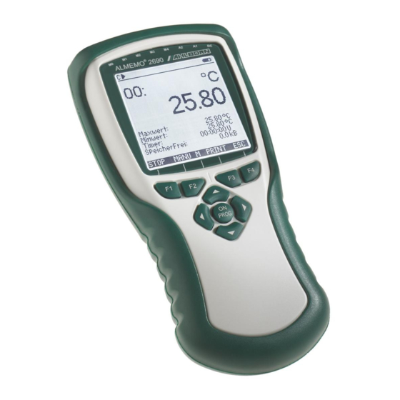
- Page 1 ____________________________ Operating Instructions Data Logger ® ALMEMO 2690-8A V4.7 20.10.2021 www.ahlborn.com...
-
Page 2: Operating Controls
1. OPERATING CONTROLS (1) Meas. inputs M0 to M4 M0 ... M4 for all ALMEMO-Sensors M10...M34 15 additional channels (2) Output sockets A1, A2 A1 Interfaces USB(ZA1919-DKU) Interface V24 (ZA 1909-DK5) Fiber optics V24 (ZA 1909-DKL) Ethernet (ZA 1945-DK) RS 422 (ZA 5099-NVL/NVB) Analog output 2 (ZA 1601-RK) A2 Network cable (ZA1999-NK5/NKL) SD card connector (ZA 1904-SD) -
Page 3: Table Of Contents
2. TABLE OF CONTENTS Operating Controls ..................2 Table of Contents ..................3 General ....................... 8 Guaranteed ..................8 Extent of the Delivery ................. 8 Waste disposal ................... 9 Safety instructions ..................10 Special notes on use ............... 11 Handling batteries / rechargeable batteries correctly ...... 11 Introduction .................... - Page 4 2. Table of Contents Function Selection ................26 Data Entry ..................26 Measuring using Measuring-Menus ............. 27 10.1 Measuring with one Measuring Point..........28 10.1.1 Selecting the Measuring Point ..........28 10.1.2 Peak Value Memory with Time and Date ......... 28 10.2 Correction of the Meas.
- Page 5 2. Table of Contents 10.5.1 Menu Multi Channel Display and Bar chart ......44 10.5.2 Differential Measurement ............44 10.5.3 Menu List of Measuring Points ..........45 10.6 Assistant-Menus for Special Meas. Operations ....... 46 10.6.1 Thermal Coefficient ..............46 10.6.2 Wet Bulb Globe Temperature ...........
- Page 6 2. Table of Contents 11.3.8 Changing the Dimension ............61 11.3.9 Selecting the Measuring Range ..........61 11.3.10 Function Channels ..............64 11.3.11 Special meas. ranges, linearization, calibration ...... 65 11.4 Special Functions................66 11.4.1 Print Cycle Factor ..............66 11.4.2 Minimum Sensor Supply Voltage ..........
- Page 7 2. Table of Contents 14.1 Technical Data ................. 81 14.2 Product overview ................82 14.3 Index ....................83 Your contact ....................88...
-
Page 8: General
3. GENERAL Congratulations for buying this innovative ALMEMO ® data logger. By means of the patented ALMEMO ® connectors the device configures itself and with the help of menus and help windows the operation should not be too difficult. However, the device allows the connection of a great variety of sensors and peripherals with many special functions. -
Page 9: Waste Disposal
3. General Waste disposal The pictogram showing a waste bin crossed through means that the product is subject to European Union regulations on segregated waste disposal. This applies both to the product itself and to any accessories marked with the same symbol. Disposal of any such item as unsorted domestic waste is strictly forbidden. -
Page 10: Safety Instructions
4. SAFETY INSTRUCTIONS DANGER Danger to life and limb, risk of damage to equipment Read the instructions carefully before starting to operate the device. Please ensure that you comply with all general safety advice and the special safety instructions included in other chap- ters. -
Page 11: Special Notes On Use
4. Safety instructions Special notes on use If the device is brought into the work-room from a cold environment • there is a risk that condensation might form on the electronics. In meas- uring operations involving thermocouples pronounced changes in tem- perature may cause substantial measuring errors. -
Page 12: Introduction
2690-8 is a new instrument from the unique product range of measuring devices that are all equipped with the ALMEMO ® connector system, which has been patented by Ahlborn GmbH. The intelligent ALMEMO ® connector provides important advantages with regard to the connection of sen- sors and peripherals as all parameters are stored in an EEPROM within the connector. -
Page 13: Sensor Programming
5. Introduction 5.1.1 Sensor Programming The measuring channels are automatically programmed by the ALMEMO ® con- nectors. However, the user can easily complete or modify the programming via keyboard or via interface. Measuring Ranges There are corresponding measuring ranges for sensors with a non-linear char- acteristic such as 10 thermocouple types, Ntc and Pt100 sensors, infrared sen- sors, and flow sensors (rotating vanes, thermoanemometers, pitot tubes). -
Page 14: Measurement
5. Introduction The base value and the factor allow for a further scaling of the corrected meas- ured value of each measuring channel for zero point and slope. The decimal point position can be set by the exponent. By setting to zero and entering the nominal value the scaling values can be automatically calculated. -
Page 15: Process Flow Control
5. Introduction sensors, dynamic pressure sensors and O2 sensors. With infrared sensors the parameters zero point and slope correction are used for background tempera- ture and emissivity factor. Max and Min Value Each measurement involves an acquisition and storage of the Max value and the Min value including the time and date. - Page 16 5. Introduction Data Memory During the cycle, all measured values can be manually or automatically stored in an EEPROM. The memory capacity is, as standard, 1024 Kilobyte, which allows up to 200.000 measured values. The memory organisation can be configured as linear or ring memory.The output can be carried out via the display or the interface.
-
Page 17: Initial Operation
6. INITIAL OPERATION Connect transducers to the sockets M0 to M4 (1), s. 8. Sensor connection with batteries/accumulators or mains adapter on DC (3) s. 7.1, 7.3 Power supply (6), s. 7.6 Switch-on Press key ON / PROG Automatical display of the last measuring menu, s. 10. keys Menu selection call up with key: MEAS.-Menus:... -
Page 18: Power Supply
7. POWER SUPPLY Power can be supplied to the instrument in any of the following ways : 3 AA NiMH batteries with integrated charge circuitry (supplied as standard). 3 AA alkaline batteries Mains adapter 12 V, 1,5 A, with ALMEMO ®... -
Page 19: Mains Operation
7. Power supply Mains operation To power the device from an external source preferably use the mains adapter ZA 1312-NAx (12 V / 1,5 A); connect this to the DC socket (3). The sensor volt- age is set automatically to 12 volts. If rechargeable batteries are being used, these will then be charged. -
Page 20: Data Buffering
7. Power supply Data buffering The sensor programming is stored in the EEPROM of the sensor connector, the calibration and the programmed parameter of the device is fail-safe stored in the EEPROM of the device. Time and date are buffered by a lithium battery so that storage of the data is also guaranteed without batteries and when the de- vice is switched off. -
Page 21: Connection Of The Transducers
8. CONNECTION OF THE TRANSDUCERS Any ALMEMO ® sensors can be connected to the ALMEMO ® input sockets M0 to M4 of the measuring instrument (1). For connecting existing sensors it is only necessary to connect a corresponding ALMEMO ® connector. Transducers A detailed description of the comprehensive ALMEMO ®... -
Page 22: Isolation
8. Connection of the Transducers Advantage of the device-internal channels: If several sensors are being used for the same application, they do not have to be reprogrammed and can be freely exchanged without losing their function channels. If, however, the whole application operates with just one sensor, then programming in the sensor itself makes more sense. - Page 23 8. Connection of the Transducers equipped with optocouplers. At electrically not isolated cables of the analog out- put, the registration device or the sensors have to be potential free. Electrically isolated A/D converter (option GT) With option OA2690-GT the analog inputs downstream from the A/D converter are also electrically isolated from the device itself and from the power supply by means of optocouplers.
-
Page 24: Display And Keypad
9. DISPLAY AND KEYPAD Display and Menu Selection The display (5) of the measuring instrument ALMEMO 2690-8 consists of a dot matrix LCD display with 128x128 dots, or 16 lines with 8 dots. For the acquisition of measuring data with the required functions and for the programming of the process control, the sensors and the device parameters, 3 categories of menus are available: Measuring-Menus (s. -
Page 25: Function Keys
9. Display and Keypad Function Keys C © REC COM l© ©l R01 * ´´´´´´µµµµ¶ ¯¯¯¯¯¯¯¯¯¯¯¯¯¯¯¯¯¯¯¯¯ The function of the keys (6) can be different in the various menus. It is indicated by Velocity abbreviations in the bottom line of the display æ... -
Page 26: Function Selection
9. Display and Keypad Function Selection C © REC COM l© ©l R01 * ´´´´´´µµµµ¶ ¯¯¯¯¯¯¯¯¯¯¯¯¯¯¯¯¯¯¯¯¯ Each menu consists of a number of func- Velocity tions that, possibly, have to be used or pro- æ » H º grammed during operation. 28.67 To set measured value to Help window at... -
Page 27: Measuring Using Measuring-Menus
MEASURING USING MEASURING-MENUS After the first switch-on, the device shows the C © REC COM l© ©l R01 * ´´´´´´µµµµ¶ menu Meas. points list (s. 10.5.3). It offers a ±±±±±±±±±±±±±±±±±±±±±±±±±±±±±±±±±±±± Meas.points list: Comment good overall view over the whole measuring sys- Time: 12:34:56 Date:01.01.04 Cycle-timer: 00:00:30 nS... -
Page 28: Measuring With One Measuring Point
10. Measuring using Measuring-Menus Measuring with one Measuring Point 10.1 C © REC COM l© ©l R01 * ´´´´´´µµµµ¶ Standard display ¯¯¯¯¯¯¯¯¯¯¯¯¯¯¯¯¯¯¯¯¯ The menu shows a measuring Standard display point in the largest display with measuring point, Velocity comment and dimension. Some symbols serve æ... -
Page 29: Correction Of The Meas. Value And Compensation
10. Measuring using Measuring-Menus Due to the continuous measurement the current measured value will be imme- diately displayed after the clearing process. Furthermore, the peak values are cleared at each start of a measurement, if the device has been correspondingly configured (standard setting, s. -
Page 30: Zero Point Adjustment
10. Measuring using Measuring-Menus 10.2.2 Zero Point Adjustment Many sensors must be adjusted at least once or at regular intervals to compen- sate for instabilities. For this purpose, a specific zero point adjustment is avail- able, in addition to the ´Set Meas. Value to Zero´ mentioned above, for not in- fluencing the scaling. -
Page 31: Two-Point Adjustment With Setpoint Entry
10. Measuring using Measuring-Menus 1. Setting up a means of calibration for the zero point: Setpoint 1: 07.00 Select function Setpoint 1: <ADJ> Zero point adjustment with key: 07.00 º The adjustment meas. value is recorded: In the case of pH probes, the standard values, base value 7.00 and slope -0.1689, can be restored by pressing the key <CLEAR>... -
Page 32: Temperature Compensation
10. Measuring using Measuring-Menus 10.2.5 Temperature Compensation Sensors with measured values that are strongly depending on the temperature of the measuring medium are, in most cases, equipped with a specific temper- ature sensor and the instrument will automatically perform a temperature com- pensation (s. -
Page 33: Cold Junction Compensation
10. Measuring using Measuring-Menus Atm. pressure 1013 mbar Enter atm. pressure in the 'Atm. pressure' function Atm. pressure 0938 mbar Atmospheric pressure is measured internally Atm. pressure 0938 mbar ´Atm. pressure´ function with active compensation To use internal atmospheric pressure sensor - press keys PROG <CLEAR>... -
Page 34: Measuring Point Scans And Output
10. Measuring using Measuring-Menus Measuring point scans and Output 10.3 Measuring point scans can be used to acquire C © REC COM l© ©l R01 * ´´´´´´µµµµ¶ the measured values of all measuring points at ±±±±±±±±±±±±±±±±±±±±±±±±±±±±±±±±±±±± Time: 12:34:56 Date:01.01.04 particular times, either manually or cyclically Cycle timer: 00:00:30 nS over a period of time, which means to store or to... -
Page 35: Memory Space, Memory Output, Clearing The Memory
10. Measuring using Measuring-Menus Change format: <FORM> Cycle Timer: 00:02:00Sn Format columns next to each other ´n´: <FORM> Change format: Cycle Timer: 00:02:00St Format table ´t´: <START> Starting a cyclic measuring point scan: For control purposes the following symbols will continuously, i.e. for the whole meas.period, be indicated in the status line: The start arrow lights up ´... -
Page 36: Displaying Measured Values As A Line Diagram
10. Measuring using Measuring-Menus 10.3.5 Displaying Measured Values as a Line Dia- gram When using the menu Line diagram the meas. value of the selected channel is indicated as a line chart with 100x200 dots as soon as a meas- urement is started. -
Page 37: Averaging
10. Measuring using Measuring-Menus Averaging 10.4 The average value of the measured value is required for various applications: e.g. Smoothing of a largely varying measured value (wind, pressure etc.). The average flow velocity in a ventilating channel. Hourly or daily average values of weather data (temp., wind etc.). As above, of consumption values (current, water, gas etc.). -
Page 38: Damping Of Meas. Values By A Sliding Averag. Window
10. Measuring using Measuring-Menus 10.4.1 Damping of Meas. values by a Sliding averag. window The first possibility of averaging concerns only the measured value of the indi- cated channel and helps to damp measured values of an unstable or strongly fluctuating nature, e.g. -
Page 39: Array Measurement
10. Measuring using Measuring-Menus <STOP> 1. Stop measurement, if it is started: Averaging mode: CONT 2. Set the averaging mode (s. 9.5): Damping: For smoothing a meas. value select damping: Conv. rate:10M/sCont: Switch the continuous scanning off, if required: 3. Clear avg. value by selecting it (s. 9.4) and using: <CLR>... -
Page 40: Averaging Over The Measuring Time
10. Measuring using Measuring-Menus 8. Stop the measurement with key: <STOP> 01: 11.43 m¡ 9. Record all points according to steps 6 to 8: 10. Clear the array and new measurement with key: <CLEAR> 11. Back to the measuring menu: <ESC>... -
Page 41: Averaging Over The Cycle
10. Measuring using Measuring-Menus Measuring duration If you want to stop a measuring operation or an averaging process (see above) after a certain length of time, you can program the measuring duration in the menu Times - Cycles or in a user menu; (this function is displayed in the status bar with ´... -
Page 42: Averaging Over Several Measuring Points
10. Measuring using Measuring-Menus Averaging mode: CYCL Setting the averaging over cycles: <CLR> Select and clear cycle using the key: Cycle timer: 00:00:00 Check: » <START> © Start measurement, averaging in progress: <MANU> © ... Manual measuring point scan: Average value from one scan to the next scan: Average value: 13.24°C For recording the average values an additional function channel ... -
Page 43: Volume Flow Measurement
10. Measuring using Measuring-Menus 10.4.9 Volume Flow Measurement The volume flow in flow channels can be calcu- C © REC COM l© ©l R01 * ´´´´´´µµµµ¶ ±±±±±±±±±±±±±±±±±±±±±±±±±±±±±±±±±±±± lated by multiplying the average flow velocity 01: 11.67 mls Volocity |¹¹¹¹¹¹¹¹¹¸¹¹¹¹¹¹¹¹¹¸¹¹¹¹¹¹¹¹¹¸¹¹¹¹¹¹¹¹¹¸¹¹¹¹¹¹¹¹¹|¹¹¹¹¹¹¹¹¹¸¹¹¹¹¹¹®®®¸®®®®®®®®®¸®®®®®®®®®¸®®®®®®®®®| and the cross-section surface. The functions 5.00 S220 mls 15.00... -
Page 44: Display Of Several Measuring Points
10. Measuring using Measuring-Menus Display of Several Measuring Points 10.5 The already mentioned measuring menus allow, on principle, only the selection and display of one measuring point. This chapter provides a description on how you can get several measuring points with your selection of functions simulta- neously on the display. -
Page 45: Menu List Of Measuring Points
10. Measuring using Measuring-Menus 10.5.3 Menu List of Measuring Points The best overview of the meas. system incl. all C © REC COM l© ©l R01 * ´´´´´´µµµµ¶ meas. values, time of day, date and cycle is ob- ±±±±±±±±±±±±±±±±±±±±±±±±±±±±±±±±±±±± Meas.points list: Comment tained with the menu . -
Page 46: Assistant-Menus For Special Meas. Operations
10. Measuring using Measuring-Menus Assistant-Menus for Special Meas. Opera- 10.6 tions Special measuring operations, i.e. thermal coefficient or wet bulb globe temper- ature, require a series of sensors in a particular arrangement and function chan- nels programmed for calculating the required variables. To ensure that these two special measuring operations can be performed quickly and easily there is a special assistant menu for each. -
Page 47: User Menus
10. Measuring using Measuring-Menus User Menus 10.7 When studying the measurement menus you may have noticed that the display of the meas. value and the combination of functions does not always match your applications in an optimum way. Therefore, you can freely configure the three user menus U1 to U3, in addition to the standard measuring menus using the software ALMEMO ®... -
Page 48: Configuration Of The Menus
10. Measuring using Measuring-Menus Number (s. 11.2.3) o 23 Number: 123-56 Range, comment: o 24 NiCr Temperature » H º Diameter mm (s. 10.4.9) o 25 Diameter: 0000 mm Cross section cm (s. 10.4.9) o 26 Cross-section: 0000 c¥ Max-time-date (s. 10.1.2) o 28 Max Time: 12:34 01.02. -
Page 49: Function Printouts
DIAMETER: 01: 00100 mm Cross section CROSS SECT: 01: 00078 cm2 Atm. pressure A.PRESSURE:+01013.mb Temp. compensation COMPENSATION:01: 25.0°C Setpoint SET POINT: 01: 1100.0°C Device designation Fa.Ahlborn,Holzkirchen Line ----------------------------- Blank line Text1 Comment Text 1 Text2 Comment Text 2 Text3 Menu Title U1... -
Page 50: Programming With Programming-Menus
PROGRAMMING WITH PROGRAMMING- MENUS Apart from the measuring functions you have al- ALMEMO 2690-8 ±±±±±±±±±±±±±±±±±±±±±±±±±±±±±±±±±±±± ready get to know some functions for process PROGRAMMING-Menus: control and sensor programming in the measur- Times, cycles Recording to memory © ing menus. Output from memory Sensor programming Here in the you find a... -
Page 51: Conversion Rate, Continuous Measuring Point Scan
11. Programming With Programming-Menus The output format (see manual 6.6.1) determines the print format at measuring point scans and at the memory output. It is programmed by using the function . Apart from the standard format ´List´ with all measured values Output form given in a list, the output format ´Columns´... -
Page 52: Time And Date Of Start, Time And Date Of End
11. Programming With Programming-Menus and all measured values are always up-to-date (s. man. 6.5.1.3). This doubles the total sampling rate. In both modes all measured values can be saved and / or output at any time. The continuous storage and the continuous output of the measured values can be activated with the conversion rate using the following two functions. -
Page 53: Data Memory
11. Programming With Programming-Menus Data Memory 11.2 The basic information with regard to data storage in ALMEMO ® devices is given in the manual section 6.9. The internal data memory of the ALMEMO 2690-8 is a 1MByte EEPROM with capacity sufficient for 128.000 to 200.000 measured values (depending on the channel number). -
Page 54: Data Acquisition
11. Programming With Programming-Menus When plugging in the connector make sure that the card remains latched in position ! The ring memory mode is not supported by memory cards 11.2.2 Data Acquisition Most of the parameters, which are required for the recording of measuring data, have already been described in the menu (s. -
Page 55: Starting And Stopping Of Measurements
11. Programming With Programming-Menus measurements during a read-out to specific measurement locations or measur- ing points (s. manual 6.7). After selecting the function the 6-digit number is entered in the usual Number way (s. 9.5). In addition to the figures 0 to 9 the characters A,F,N,P,- or _ (space) can be used. - Page 56 11. Programming With Programming-Menus The following steps must be carried out in the menu Recording to memory perform a data recording in the sleep mode: Cycle: 00:05:00 1. Enter a cycle with a min. duration of 2 minutes: Storing: Ø normal: - 2.
-
Page 57: Memory Output
11. Programming With Programming-Menus 11.2.6 Memory Output * OUTPUT FROM MEMORY * The content of the data memory can, com- ±±±±±±±±±±±±±±±±±±±±±±±±±±±±±±±±±±±±± Memory Internal: 512.0 kB pletely or in parts, be output to the serial inter- Memory free: 125.8 kB face. For each output one of the three available Residual output: 12.5 kB output formats ´List´, ´Columns´... -
Page 58: Sensor Programming
11. Programming With Programming-Menus Clear memory Memory free: 384.5kB Select function (s. 9.4): Memory free <CMEM> To clear the memory, press the key: Memory free: 512.0kB Full memory capacity is indicated in function: <ESC> Cancel by using the key: Sensor Programming 11.3 As all ALMEMO ®... -
Page 59: Measuring Point Designation
11. Programming With Programming-Menus 11.3.2 Measuring Point Designation Each measuring point can be given a 10-digit alphanumeric designation to opti- mally identify the type of sensor, the measuring location or the purpose of the application. This comment will be indicated with all standard displays of meas- ured values. -
Page 60: Limit Values
11. Programming With Programming-Menus 11.3.5 Limit Values Two limit values (MAX, MIN) can be programmed and allocated to each meas- uring channel. An exceeding of limit values is handled as a fault, similar to an exceeding of meas. range limits and sensor breakage. On the display a corre- sponding arrow ... -
Page 61: Correction Values
11. Programming With Programming-Menus 11.3.7 Correction Values The correction values ZERO CORRECTION and SLOPE CORRECTION allow for correcting sensors with regard to zero point and slope (s. man. 6.3.10). Corrected Meas. Value = (Meas.Value - ZERO CORR.) x SLOPE CORR. Function: 4 Zero correct.: -----°C Zero point correction:... - Page 62 11. Programming With Programming-Menus ZA 9021FSL and a corresponding help window to identify Thermocouple Typ L the sensors: -200.0 ... 900.0 °C Transducer Conn./Cable/ Meas. Range Dim Display Sensor Pt100-1 ZA 9000-FS -200.0... +850.0 °C ITS90 P104 Pt100-2 ZA 9000-FS -200.00...+400.00 °C ITS90...
- Page 63 11. Programming With Programming-Menus Transducer Conn./Cable/ Meas. Range Dim Display Sensor Infrared 6 ZA 9000-FS 0.0... +500.0 °C Ir 6 Rotating Vanes Normal 20 FV A915-S120 0.30... 20.00 S120 Rotating Vanes Normal 40 FV A915-S140 0.40... 40.00 S140 Rotating Vanes Micro 20 FV A915-S220 0.50...
-
Page 64: Function Channels
11. Programming With Programming-Menus Transducer Conn./Cable/ Meas. Range Dim Display Sensor Volume m · Q Flow Timer 0...65000 s.10.4.6 Time FDA602Lx Temp. for Refrigerant R22 ° -90.0...+79.0 °C FDA602Lx Temp. for Refrigerant R23 ° -100.0...+26.0 °C FDA602Lx Temp. for Refrigerant R134a ° -75.0...+101.0 °C R134... -
Page 65: Special Meas. Ranges, Linearization, Calibration
11. Programming With Programming-Menus A new feature is the presence of four device-internal channels: M5 is programmed by default as differential channel M1-M0; this applies if there are two sensors with the same units and same decimal point position connected at measuring points M0 and M1. -
Page 66: Special Functions
11. Programming With Programming-Menus If a channel with a characteristic is deactivated or programmed with a different range, the characteristic is subsequently reactivated by programming the spe- cial range ´Lin´ by means of the keyboard or command 'B99'. SPECIAL FUNCTIONS Special Functions 11.4 ±±±±±±±±±±±±±±±±±±±±±±±±±±±±±±±±±±±±±... -
Page 67: Limit Value Responses
11. Programming With Programming-Menus 11.4.3 Limit Value Responses Relay Allocation As standard, both limit values of all measuring points of a device are used for fault alarms (s. 11.3.5), i.e. if an exceeding of a limit value occurs at any meas- uring point, the relay 0 responds if an Alarm Relay Cable or a corresponding Relay Adapter (s. -
Page 68: Analog Output Start And End
11. Programming With Programming-Menus 11.4.4 Analog Output Start and End In most cases the analog output of measured values to the analog output mod- ules (see manual 5) or the display as bar or line chart must be scaled to a spec- ified sub-range. -
Page 69: Reference Channel 1
11. Programming With Programming-Menus 11.4.6 Reference Channel 1 The arithmetic functions of the function channels, generally, refer to a particular measuring channel (or 2 meas. channels) (s. 11.3.10, man. 6.3.4). During the programming of a function channel the first channel of the corresponding sensor connector Mxx1 is automatically set as reference channel Mb1. -
Page 70: Device Configuration
* DEVICE CONFIGURATION * ±±±±±±±±±±±±±±±±±±±±±±±±±±±±±±±±±±±±± the menu . The de- DEVICE CONFIGURATION Device designation: Ahlborn, Holzkirchen vice designation appears in the output via in- Device: 00 V: 6.05 XY terface and facilitates the assignment within a Baud rate: 9600 Bd network. -
Page 71: Baud Rate, Data Format
11. Programming With Programming-Menus 11.5.3 Baud Rate, Data Format All interface modules are factory-set and programmed to 9600 baud. To avoid unnecessary problems when networking several devices the baud rate should not be modified but the computer should be set up accordingly. If this is not possible the values 1200, 2400, 4800, 9600bd or 57.6, 115.2 kbd can be entered in the function Baud Rate (please consider the max. -
Page 72: Hysteresis
11. Programming With Programming-Menus 11.5.7 Hysteresis In case of an exceeding of limit values the hysteresis of an alarm condition can, generally for all sensors, be set in the function Hysteresis (s. 11.3.5 and man- ual 6.2.7) within the range from 0 to 99 digits (standard setting is 10 digits). Hysteresis: Change hysteresis (0 to 99) s. -
Page 73: Data Cable
11. Programming With Programming-Menus 11.6.1 Data cable The serial interface can be used to output cyclic data logs, all function values of the measuring menus, as well as the whole programming of the sensors and the device to a computer. The ALMEMO ® data cables and the connection to the instruments are described in the manual section 5.2. - Page 74 11. Programming With Programming-Menus 0: Summated alarm 0: Alarm if any one channel of all channels is faulty 2: Assigned internally 2: Alarm for a programmable channel 3: Alarm, if one limit value - maximum of all is overshot 3: Summated alarm - maximum 4: Alarm, if one limit value - minimum of all is undershot 4: Summated alarm - minimum 8: Driven externally...
-
Page 75: Analog Output
11. Programming With Programming-Menus 11.6.3 Analog Output For an analog recording of measured values it ANALOG OUTPUT ¯¯¯¯¯¯¯¯¯¯¯¯¯¯¯¯¯¯¯¯¯ is still possible, at sockets A1 and / or A2 (2) to Output socket: connect V5 output modules with an analog out- RK Recording cable 20mA put, e.g. -
Page 76: Menu Power Supply
11. Programming With Programming-Menus Menu Power Supply 11.7 Power for the measuring instrument is usually POWER SUPPLY supplied by three AA battery cells - normally re- ¯¯¯¯¯¯¯¯¯¯¯¯¯¯¯¯¯¯¯¯¯ chargeable - or alternatively standard batteries. Battery voltage: 3.8 V Sensor voltage set: 9.0 V The power supply menu provides an estimation Sensor voltage act:... -
Page 77: The Locking And Calibration Menu (Option Kl)
11. Programming With Programming-Menus charge automatically ended. Then only will the network icon. Batteries are loaded correctly in all cases. The external charge adapter from rechargeable battery set ZA2690-AS cannot be used with this device. The locking and calibration menu (option KL) 11.8 In the you can... -
Page 78: Troubleshooting
TROUBLESHOOTING The data logger ALMEMO 2690-8 can be configured and programmed in many different ways. It allows for a connection of many different sensors, additional measuring instru- ments, alarm signalisers and peripheral devices. Due to the large variety of options it is possible that, under certain conditions, it does not perform as the user would expect. - Page 79 12. Troubleshooting ® report and, possibly, control printouts. Additionally, the software ALMEMO Control al- lows to print the monitor pages including the programming and also to save an extensive ´function test´ in the device list or the terminal operation and to print it out.
-
Page 80: Declaration Of Conformity
DECLARATION OF CONFORMITY... -
Page 81: Appendix
APPENDIX Technical Data (see manual 2.3) 14.1 Measuring inputs: ® ® 5 ALMEMO sockets for ALMEMO flat connectors Meas. channels: 5 primary channels el. isol., max. 19 add. channels for double sensors and function channels Delta-sigma >16bit, 2.5, 10, 50, 100, M/s, amplific. 1..100 AD-converter: 500M/s (Option Q5) Sensor voltage supply:... -
Page 82: Product Overview
14. Appendix Product overview 14.2 Data logger ALMEMO 2690-8A Order No. 5 inputs, max. 24 channels, 2 outputs, cascadable interface, 9 keys, LCD graphics display, real time clock, 1MB EEPROM memory Battery charger and atmospheric pressure sensor integrated MA 2690-8A... -
Page 83: Index
INDEX Action max and Action min Current output: activation mode Cycles actual contact status Cyclic Output Additional Channels Damping of Meas. values Alarm Relay Cable Data Acquisition Analog Output Data buffering Analog Output Start and End Data cable Array Measurement Data Entry Assistant-Menus 24, 46... - Page 84 15. Index Line Diagram output linearization Programming-Menus 24, 50 Locking the Programming of the Rechargeable battery Sensor Reference Channel 1 Mains operation Reference Channel 2 Max Time Reinitialisation Relais Trigger modules Meas. points list Relay Adapter Measurement Relay Allocation Measurement Time Relay-Trigger-Analogadapter Measuring Safety instructions...
- Page 85 15. Index Trigger inputs User Menus Trigger modules Volume Flow Measurement Troubleshooting Waste disposal Two-point Adjustment Wet Bulb Globe Temperature U-Sensor Min Zero Point Adjustment Zero point correction...
- Page 86 Notes...
- Page 87 Notes...
-
Page 88: Your Contact
Your contact AHLBORN Mess- und Regelungstechnik GmbH Eichenfeldstraße 1 83607 Holzkirchen Germany internet : http://www.ahlborn.com e-mail : amr@ahlborn.com Despite great care, incorrect information cannot be ruled out. Technical changes are reserved.
Need help?
Do you have a question about the ALMEMO 2690-8A and is the answer not in the manual?
Questions and answers