
Related Manuals for Ahlborn ALMEMO 470


Summary of Contents for Ahlborn ALMEMO 470
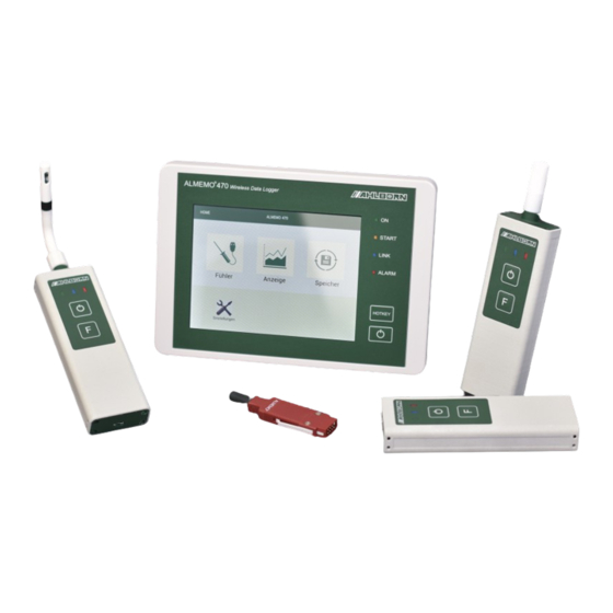
- Page 1 Produktpräsentationsbild Instruction Manual ® ALMEMO Wireless Data Logger ® Including wireless ALMEMO Sensor and ® wireless ALMEMO Interface V7 Technology English V2.1 - 1 – 01.06.2021...
-
Page 2: Global Overview
1 Global Overview ® ALMEMO 470 Wireless Data Logger Display 1 ON LED 2 START LED 3 LINK LED 4 ALARM LED 5 Hotkey 6 ON/OFF button 7 DC IN socket 8 Ethernet socket 9 ® Side view of the ALMEMO 470 wireless data logger Display 1 Micro USB socket 10... - Page 3 1 Global Overview ® Rear view of the ALMEMO 470 Wireless Data Logger Battery compartment cover 11 Fixing points for wall mount 12 ® Wireless ALMEMO Sensor Green, blue and red LEDs 13 ON/OFF button 14 F button 15 ON/OFF button 14 F button 15 Micro USB socket 16 - 3 –...
- Page 4 1 Global Overview ® Wireless ALMEMO Interface Micro USB socket 16 ® ALMEMO input socket 17 Green LED Blue LED Red LED ON/OFF button 14 F button 15 - 4 –...
-
Page 5: Table Of Contents
2 Table of Contents Global Overview..................2 Table of Contents ..................5 Explanation of Symbols ................9 Safety Notes ..................... 10 4.1 How to avoid Measuring Errors and Product Damages ...... 10 4.2 Intended Use ..................11 Product ..................... 12 5.1 Scope of Delivery ................ - Page 6 2 Table of Contents Display ..................35 7.2.4 How to delete the Function Values maximum value, minimum value, and average value ......... 35 7.3 How to perform Measuring Operations ..........37 7.3.1 How to start / stop a measuring operation ........ 37 7.3.2 How to recognize and manage Alarm Signals ......
- Page 7 2 Table of Contents Settings ..................... 58 8.1 How to set the Data Logger ..............58 8.1.1 How to set the Display Language ..........58 8.1.2 How to set a Radio Channel ............58 8.1.3 How to check the Radio Channel Utilization ......60 8.1.4 How to set a Wireless Network SSID .........
- Page 8 2 Table of Contents 8.3.1 How to enable and disable a Measuring Channel ....80 8.3.2 How to set the Channel Designation ......... 82 8.3.3 How to set Limit Values ............. 82 How to set-up a Connection for Several Data Loggers ...... 84 10 Maintenance and Care ................
-
Page 9: Explanation Of Symbols
3 Explanation of Symbols Safety note Requirement → Request Notice ➢ Result Reference referring to the legend Global Overview of the ® data logger, wireless ALMEMO sensor and wireless ® ALMEMO interface (page 2-4) back Text displayed within a software - 9 –... -
Page 10: Safety Notes
4 Safety Notes → Please read the Instruction Manual carefully and follow the safety and warning notes. → Only operate the measuring instrument in accordance with the intended use. → Do not operate the device outside of the indicated environmental conditions. -
Page 11: Intended Use
Any such usage will result in the loss of the warranty rights. In case of doubt, please contact our technical support (Phone: +49 (0)8024/3007-38, email: help@ahlborn.com). - 11 –... -
Page 12: Product
5 Product 5.1 Scope of Delivery → When unpacking, please pay attention to damages to the measuring instrument as well as to the completeness of the delivery. The precise compilation of your delivery depends on your purchase order. ® ALMEMO wireless data logger Mains adapter for the data logger USB data cable... -
Page 13: Description
5 Product ® Wireless ALMEMO interface ® Mains adapter for the wireless ALMEMO sensor ® or for the wireless ALMEMO interface ® Wall mount for wireless ALMEMO sensor ® or for the wireless ALMEMO interface ® CD ALMEMO software & documentation ®... - Page 14 5 Product Status LEDs data logger Connected to power supply, Flashing battery is being charged Constant light, Switched on and / or battery fully Display on charged Constant light, Power saving mode Display off START Flashing Measurement has been started ®...
- Page 15 5 Product Radio connection The wireless data logger receives the measured data, measured and buffer- ® saved by the ALMEMO wireless sensors, via a radio connection. In case a direct connection to the wireless data logger is not possible, every ®...
-
Page 16: Wireless Sensor Overview Key Assignment And Led States
5 Product 5.3 Wireless Sensor Overview key assignment and LED states Legend LEDs off LEDs LEDs are LEDs are Time 5 Sec light up flashing flashing rarely sequence Hold period - 16 –... -
Page 17: Initial Operation
6 Initial Operation How to switch the data logger on 1. Insert the DC plug of the included mains adapter for the data logger into the DC IN socket 8 of the data logger and the mains plug into a power socket. ➢... - Page 18 6 Initial Operation ➢ All LEDs of the ALMEMO ® ® wireless sensor will light up; the ALMEMO wireless sensor is being switched on. ➢ The green LED of the ALMEMO ® wireless sensor lights up and only ® flashes briefly as long as the battery is being charged. The ALMEMO wireless sensor is switched on.
- Page 19 6 Initial Operation simultaneously. If no connection could be established after a while, it might be because no pairing data for this sensor is saved on the data logger. Please check if the sensor is listed in the table in the menu Settings>Wireless network>Sensor pairing.
-
Page 20: Usage
7 Usage 7.1 How to prepare the Measurements 7.1.1 How to connect the Power Supply Connect the power supply to the data logger Only use the included mains adapter. Only for this mains adapter, we can guarantee a continuously stable power supply. →... -
Page 21: How To Check The Battery Charge Level
7 Usage ➢ The green LED of the ALMEMO ® wireless sensor flashes as long as the wireless sensor is charged. In case the wireless sensor is being charged while it is switched on, the green LED lights up and flashes only briefly. -
Page 22: How To Switch The Data Logger On/Off
7 Usage Check the battery charge level of the wireless sensor ! The wireless sensor must be switched on. → Shortly press the ON/OFF button 14 of the ALMEMO ® wireless sensor. ➢ The LEDs will display the battery charge level of the wireless sensor for 8 seconds. -
Page 23: How To Use The Power Saving Mode Of The Data Logger
7 Usage ➢ The ON LED 2 of the data logger lights up as soon as the battery is fully charged. Switch the data logger off → Press the ON/OFF button 7. ➢ The display of the data logger and the status LEDs will go out. ➢... -
Page 24: How To Connect /Disconnect An Almemo
7 Usage ➢ You can end the power saving mode by tapping on the display. ® 7.1.5 How to connect /disconnect an ALMEMO Sensor to ® the Wireless ALMEMO Interface Connect a sensor ® The wireless ALMEMO interface ® is a ALMEMO wireless sensor ®... -
Page 25: How To Connect The Wireless Sensor With The Data Logger
7 Usage ➢ The green LED of the ALMEMO ® wireless sensor will light up and only ® flashes briefly as long as the batteries are charged. The ALMEMO wireless sensor is switched on. ➢ In case pairing data is saved on the wireless sensor and the sensor tries to connect to the data logger, the blue LED flashes slowly. - Page 26 7 Usage neither light up nor flash. In case the green and the blue LED flash simultaneously after the wireless sensor has been switched on, the wireless sensor was already paired with a data logger and pairing data is saved on the wireless sensor.
- Page 27 7 Usage stored and queries the pairing data from the data logger. This may take some time. In case only the red LED flashes approximately 7 times instead of all LEDs flashing simultaneously, pairing data is already stored on the wireless sensor.
- Page 28 7 Usage ➢ In the line Connection quality , the connection quality will be indicated by three fields. Description Message regarding connection quality All fields green Very good connection Two fields green Good connection One field green Poor connection All fields grey No connection In case you want to connect several wireless sensors to a data logger, repeat steps 4 to 7 for every single wireless sensor.
- Page 29 7 Usage ➢ The display 1 of the data logger will show the home screen. ➢ The display 1 of the data logger will show the home screen and the ON LED 2 of the data logger flashes as long as the data logger is being charged.
-
Page 30: How To Terminate The Connection Between Wireless Sensor And Data Logger
7 Usage INIT featuring the symbol as long as initialization data is being transferred. ➢ The blue LED of the ALMEMO ® ® wireless sensor is lit. The ALMEMO wireless sensor is connected to the data logger. The blue LED flashes if data is being transferred to the data logger. - Page 31 7 Usage The wireless sensor and the data logger save the pairing data during the pairing process. After being switched off and then on again, both devices connect automatically. During the unpairing process it is therefore mandatory to delete the pairing data from the data logger as well as from the wireless sensor.
- Page 32 7 Usage In case the data logger and the wireless sensor cannot be connected, and you still want to delete the pairing data from the wireless sensor, follow the following steps: ! The wireless sensor needs to be switched on. The green LED is lit. →...
-
Page 33: How To Display Measured Values
7 Usage If you want to unpair all connected wireless sensors simultaneously, in Unpair all sensors. step 4 tap on the button → Delete the pairing data from the wireless sensor as well (see section Delete pairing data from wireless sensor without connection). 7.2 How to display Measured Values ! The data logger needs to be switched on. -
Page 34: How To Display Measured Values In The User Menu
7 Usage 1. Tap on the cell in the header of the column, whose display you want to change. 2. Tap on the desired type of measured value. ➢ The selected type of measured value will be displayed in the header. The relevant measurement data will be displayed in the column. -
Page 35: How To Display Measured Values In The Measured Value
7 Usage connected, the measuring points and the measured values will be displayed. Hide measured values in the user menu Mx.x.x 1. Tap on the measuring point name in the cell, whose measured values you want to hide. Hide. 2. Tap on ➢... - Page 36 7 Usage 1. Select the type of measured value of a table cell displayed in the menu channel list as described in 7.2.1 How to display measured values in a channel list. ➢ The measuring channels of the connected wireless sensors will be displayed with the desired measurement data.
-
Page 37: How To Perform Measuring Operations
7 Usage 7.3 How to perform Measuring Operations During a measuring operation, the received measurement data will be saved to the data logger according to the selected measuring cycle and output cycle (8.2.4 How to set the Measuring Cycle and chapter 8.2.5 How to set the Output Cycle). -
Page 38: How To Recognize And Manage Alarm Signals
7 Usage ➢ Measurement data received from the wireless sensor will be saved to the data logger with a timestamp. ➢ In the upper line of the display 1 the arrows of the icon will start flashing. In case the data storage mode ring memory is enabled, the arrows flash in orange. - Page 39 7 Usage featuring the following information: Alarm occurrence time, time of alarm end, and the corresponding measuring channel. In addition, an acoustic signal will sound (provided that the signal transmitter has been switched on) and the ALARM LED 5 will light up. Recognize an alarm If an alarm is triggered in the data logger, a dialog field informs you about the new entry of an alarm in the alarm list.
-
Page 40: How To Detect A Radio Connection Loss
7 Usage UNDERRANGE Lower range limit underrun OVERRANGE Upper range limit overrun Manage alarms in the alarm list 1. In the home screen, tap on Display to open the alarm list. 2. Go to the tab alarm list 3. Enable the checkbox next to the alarm you want to delete. The most recent alarm is on the top of the list. -
Page 41: How To Query The Memory Status
7 Usage measured value display as well as in the menu Sensor overview>Sensor SX.X> Measuring channels. Additionally, an acoustic signal will sound and the ALARM LED 5 will light BREAK Measured values will be displayed without the symbol as soon as the sensor break no longer exists and the set output cycle has run out, which means that a new measured value has been sent to the data logger. -
Page 42: How To Manage Measurements
7 Usage 7.4 How to manage Measurements 7.4.1 How to export measurements from the data logger to a PC ! The data logger must either be connected to the PC via a USB connection or via an Ethernet network (see chapter 7.5 How to connect the Data Logger to a PC). -
Page 43: How To Name Upcoming Measurements
7 Usage of the measurement that was measured during the selected time interval. 7. If you would rather save the Coordinated Universal Time (UTC) as the timestamp for your export file than the time set in your data logger, tick Using Coordinated Universal Time (UTC) the checkbox in the... -
Page 44: How To Delete A Measurement
7 Usage ➢ If you start a measurement, the measurement will be given the desired name and will be listed with this name in the table in the menu Manage measurements. ➢ If you stop a measurement and start a new one without selecting a new name for the next measurement, an ascending serial number will be added to the measurement name. -
Page 45: How To Establish A Usb Connection
CD on hand, you can download the driver for USB connections with ® ALMEMO measuring devices under the following link: https://www.ahlborn.com/download/treiber/ After the download is complete, the files need to be unzipped to be installed. How to install the USB driver before connecting the USB data cable ®... - Page 46 7 Usage or the AMR WinControl software. In addition, you can use the ® ALMEMO 470 MeshViewer software via the USB connection. Installation after accidentally connecting the USB data cable ® 1. Insert the ALMEMO software & documentation CD in the CD drive of your PC.
-
Page 47: How To Establish An Ethernet Connection
7 Usage Identify the COM port number 1. On the PC keyboard simultaneously press the Windows key and the R key. ➢ The dialog box will open. devmgmt.msc 2. Enter and press Enter. Device Manager ➢ The dialog box will open. Connections (COM &... -
Page 48: How To Establish A Connection Via An Ethernet Network
7 Usage ➢ Via the Ethernet connection you can export measured values to the ® PC, use the AMR WinControl software, and use the ALMEMO MeshViewer software. 7.5.3 How to establish a Connection via an Ethernet Network ® The IP address of the wireless ALMEMO data logger is preset as a dynamic IP address. -
Page 49: How To Use Amr Wincontrol
7 Usage Device settings. 3. Tap on Communication. 4. Tap on Reboot of the network connection Start. 5. In the line tap on ➢ The network connection will be restarted and the new IP address of IP address the data logger will be displayed in the line 7.5.4 How to use AMR WinControl Use software version 8.2.8.0 or higher to be able to connect to the ®... -
Page 50: How To Use Almemo ® Control
7 Usage Connecting via Ethernet network Connection Network. 6. In the line , click one 7. Check the IP address of the data logger in the data logger menu Settings>Device settings>Communication. IP address or computer 8. Enter the IP address in the field next to name 9. - Page 51 8. Enter the baud rate set in the data logger. You can find the set baud rate in the data logger menu Settings>Device settings>Communication. Protocol. 9. Click on the field next to ALMEMO 470. 10. Click on 11. Click on Connection via Ethernet network Interface.
-
Page 52: How To Use The Mounting Support For The Data Logger
7 Usage 7.6 How to use the Mounting Support for the Data Logger 7.6.1 How to hang the data logger on the wall mount Release levers Fastening hooks Screw holes 1. Use screws to attach the wall mount for the ®... -
Page 53: How To Remove The Data Logger From The Wall Mount
7 Usage 7.6.2 How to remove the Data Logger from the Wall Mount → Press both release levers of the wall mount and pull the data logger up to remove it from the wall mount. Release levers 7.6.3 How to use the Pedestal as a Table Top Console →... -
Page 54: How To Use The Pedestal As A Wall Mount
7 Usage 7.6.4 How to use the Pedestal as a Wall Mount 1. Loosen the screws of the pedestal using a screws screwdriver. screw holes 2. Open the pedestal. 3. Use screws to attach the housing of the pedestall (the bottom part of the pedestal) to the desired position on the wall. -
Page 55: How To Use The Wall Mount For The Almemo Wireless Sensor
7 Usage ® 7.7 How to use the Wall Mount for the ALMEMO Wireless Sensor 7.7.1 How to install the Magnetic Mount If you have a pacemaker or an implanted defibrillator, do not use a magnetic wall mount. Magnets can affect the functionality of pacemakers and implanted defibrillators. -
Page 56: How To Use The Mounting Plate
7 Usage 7.7.2 How to use the Mounting Plate 1. Use screws to fasten the mounting plate to the desired position on the wall. ® 2. Slide the ALMEMO wireless sensor above the mounting plate until it noticeably snaps in. ➢... -
Page 57: How To Use The Suction Cup Fastening
7 Usage 7.7.3 How to use the Suction Cup Fastening 1. Firmly press the suction cups of the suction cup fastening on a smooth surface, such as a glass pane. Make sure that the smooth surface is free of dirt and grease. ®... -
Page 58: Settings
8 Settings 8.1 How to set the Data Logger 8.1.1 How to set the Display Language 1. In the home screen click on the button to change the language that is used throughout all menus of the data logger. 2. Tap on the desired language. ➢... - Page 59 8 Settings Radio channel 2405 2410 2415 2420 2425 2430 2435 2440 Radio channel 2445 2450 2455 2460 2465 2470 2475 2480 Every radio channel overlaps with at least one WiFi channel as schematically illustrated in the image below. To detect free radio frequencies you can use computer programs, tablet apps, or smart phone apps suitable for this purpose.
-
Page 60: How To Check The Radio Channel Utilization
8 Settings The radio channel will not be changed until you select another radio AUTO channel or you tap on again. The capacity utilization of the radio channel by other radio applications may change meanwhile. 8.1.3 How to check the Radio Channel Utilization When the utilization of the radio channels is checked, the current utilization will be displayed in percent (%) and decibels milliwatt (dBm). -
Page 61: How To Set A Wireless Network Ssid
8 Settings 8.1.4 How to set a Wireless Network SSID ! No wireless sensor must be connected to the data logger. If you want to operate several data loggers in parallel, make sure to set a different wireless network SSID for each data logger. 1. - Page 62 8 Settings featuring short measuring cycles are connected to the data logger. In this mode, measuring data of the wireless sensors is sent to the data logger and configuration packets are sent from the data logger to the wireless sensors. Important: No network information of the wireless sensors is sent.
-
Page 63: How To Set Time, Date And Time Zone
8 Settings displayed with every sensor. In the measured value display, the last Configuration measured values received before the operating mode STOP was set will be displayed with the symbol on every measuring channel. Configuration In the operating mode the data logger is not able to ®... -
Page 64: How To Set The Data Storage Mode
8 Settings Set a time zone Measured data will be stored in the wireless sensor with a timestamp. To be sure that the timestamp does not show the time set in the data logger but rather the Coordinated Universal Time (UTC) the time zone in which the data logger and the wireless sensor are located must be set on the data logger. -
Page 65: How To Set The Storage Capacity
8 Settings 8.1.9 How to set the Storage Capacity ! No measurement may be started. 1. In the home screen tap on Memory Memory total. 2. Tap into the field next to 3. Tap on the desired storage capacity. ➢ In the data storage mode ring memory, the oldest data of a running measurement will be overwritten when the memory is full. -
Page 66: How To Set A Static Or A Dynamic Ip Address
8 Settings 8.1.11 How to set a static or a dynamic IP address ! There shall be no connection via Ethernet between the data logger and another device. Set the static IP address 1. In the home screen, tap on Settings Device settings. -
Page 67: How To Set The Baud Rate For The Usb Connection
8 Settings ➢ The data logger receives a dynamic IP address that will be assigned by the respective DHCP server in the Ethernet network. This process may take some time. ➢ The current IP address will be displayed in the field next to address . -
Page 68: How To Find The Software Version Of The Data Logger
8 Settings 8.1.14 How to find the Software Version of the Data Logger Display software version → You will find the display software version in the right lower corner on the home screen. Wireless network software version 1. In the home screen, tap on Settings Wireless network. -
Page 69: How To Set The Display Brightness
8 Settings triggered in the data logger, a dialog field will open informing you that a new alarm has been added to the alarm list. ➢ If the alarm dialog is switched off, the button next to Alarm dialog grey and features the word OFF. 8.1.17 How to set the Display Brightness 1. -
Page 70: How To Display The Wireless Sensors
8 Settings To change the setting of a wireless sensor that is in sleep mode, you should temporarily interrupt the energy saving mode (see chapter 8.2.7 How to enable / disable Sleep Mode). 8.2.1 How to display the Wireless Sensors →... -
Page 71: How To Set The Measuring Cycle
8 Settings Transmission power Transmission power in Selection in dBm 0 dBm 1 mW Medium 10 dBm 10 mW Maximum 17 dBm 100mW ➢ The wireless sensor will send at the selected transmission power. 8.2.4 How to set the Measuring Cycle During the measuring cycle, the measurement data will be stored with a timestamp in the wireless sensor. -
Page 72: How To Set The Output Cycle
8 Settings 8.2.5 How to set the Output Cycle During the measuring cycle, the measurement data will be stored with a timestamp in the wireless sensor. The data will be sent to the data logger according to the output cycle. A maximum of 128 measured values can be stored in the wireless sensor, so that in the output cycle these values will be sent together to the data logger. - Page 73 V1.04 and higher and for data loggers with software version V1.03 and higher. For software updates please contact the technical support (phone +49 8024 3007-38, email help@ahlborn.com). In case you want to make settings regarding designation of the sensor, transmission power, measuring cycle, output cycle, or active...
- Page 74 8 Settings Power saving. 5. Tap on The sleep mode will not be activated until the wireless sensor is being paired again. ® To extend the battery life, for wireless ALMEMO interfaces the sensor supply is being automated during sleep mode. ®...
- Page 75 8 Settings → To pair the sensor once again with the data logger, follow the steps 4 to 7 in the chapter 7.1.7 How to connect the Wireless Sensor with the Data Logger. ➢ All LEDs of the ALMEMO ® wireless sensor are flashing simultaneously.
- Page 76 8 Settings every 10 seconds. The green LED is flashing simultaneously with the blue one when the batteries of the wireless sensor are being charged. → Press and hold the ON/OFF key 14 of the wireless sensor for quite some time. ➢...
- Page 77 8 Settings the field next to Radio network registration. However, the sensor is not in energy saving mode when the green LED is lit respectively is flashing when the batteries are being charged. The blue LED of the wireless sensor is lit, respectively is flashing when data is being transferred to the data logger.
- Page 78 8 Settings 1. In the home screen tap on Sensor overview 2. Tap on the arrow at the end of the line of the wireless sensor, of which you want to disable the sleep mode. Power settings. 3. Tap on Radio network registration.
-
Page 79: How To Automate Sensor Supply And Settling Time
8 Settings 8.2.7 How to automate Sensor Supply and Settling Time ® ALMEMO Sensors that are powered via the sensor supply of the ® ALMEMO wireless interface will possibly consume permanently a lot of current. To save energy and to extend the battery life, the sensor supply can be switched off whenever no measured values are ®... -
Page 80: How To Set A Measuring Channel
8 Settings 2. Tap on the arrow at the end of the line of the wireless sensor, whose software version you want to know. ➢ The software version of the wireless sensor will be displayed in the Software version line 8.3 How to set a Measuring Channel ®... - Page 81 8 Settings Measuring channels. 3. Tap on 4. Untick the checkbox in the line of the measuring channel you want to disable. ➢ The measuring channel is disabled and the measurement data of this measuring channel will not be stored in the wireless sensor and not be transferred to the data logger.
-
Page 82: How To Set The Channel Designation
8 Settings 8.3.2 How to set the Channel Designation ! The wireless sensor needs to be connected to the data logger. 1. In the home screen, tap on Sensor overview 2. Tap on the arrow at the end of the line of the wireless sensor whose measuring channel you want to name. - Page 83 8 Settings Limit value, maximum. 6. Tap on the field next to 7. Enter the desired upper limit value. Limit value, minimum. 8. Tap on the field next to 9. Enter the desired lower limit value. ➢ The desired limit values are set. In case the limit value is overshot respectively undershot, the measured value will be displayed in red (limit value overshoot) respectively in blue (limit value undershoot) and an acoustic signal will sound in the data logger (provided that the...
-
Page 84: How To Set-Up A Connection For Several Data Loggers
9 How to set-up a Connection for Several Data Loggers ® You can operate several ALMEMO 470 wireless data loggers in ® parallel. Which wireless sensor will connect to which ALMEMO wireless data logger is determined via the pairing of the wireless sensor and the data logger. - Page 85 9 How to set-up a Connection for Several Data Loggers 10. Repeat steps 2. to 9. for every data logger you want to operate in parallel. Make sure that you set a different wireless network SSID for every data logger. Additionally, make sure that you set different radio channels.
-
Page 86: Maintenance And Care
10 Maintenance and Care How to clean the Housing of the data logger ! The data logger needs to be switched off. ! The data logger needs to be disconnected from the power supply. → If soiled, clean the housing with a damp cloth. Do not use aggressive detergents or solvents for cleaning. - Page 87 The sensitive sensor element is below the protection cap. → For calibration or replacement of the sensor send your wireless ® ALMEMO sensors to the Ahlborn Company. How to replace batteries of the wireless sensor ® To avoid product damages, do not open the wireless ALMEMO ®...
-
Page 88: Questions And Answers
11 Questions and Answers 11.1 General Questions Question Possible causes Possible solution The wireless Overloaded radio Select another radio channel for the sensor does not channel wireless network of the data logger (see connect to the chapter 8.1.2 How to set a Radio data logger Channel) Wireless sensor is... - Page 89 11 Questions and Answers Overloaded radio Select another radio channel for the channel wireless network of the data logger (see chapter 8.1.2 How to set a Radio Channel) The wireless Serial number of Delete the pairing data from the data sensor connects the wireless logger, to which you do not want to...
- Page 90 11 Questions and Answers ® ® No ALMEMO Connect the ALMEMO D6 or D7 plug of ® sensor has been an ALMEMO sensor to the wireless ® connected to the ALMEMO interface (see chapter 7.1.5 wireless 7.1.5 How to connect /disconnect an ®...
- Page 91 (see chapter 10 Maintenance and Care, section How to replace the batteries of the data logger). → In case we could not answer your question, please contact the technical support (Phone: +49 (0)8024/3007-38, email: help@ahlborn.com). - 91 –...
-
Page 92: How To Reset The Data Logger Settings
11 Questions and Answers 11.2 How to reset the Data Logger Settings If you follow the following steps, all settings made so far will be deleted. After the reset, the saved measurements will no longer contain start and stop times (i.e. no timestamps will be available). With the reset taking effect, the time and date in the data logger will be set to 00:00 (time) and 00.00.2000 (date). -
Page 93: How To Interpret The Led Status Of The Wireless Sensor
11 Questions and Answers 11.3 How to interpret the LED Status of the Wireless Sensor The wireless sensor communicates its current condition using the three LEDs green, blue, and red. LED description Message Status The green LED is lit. The wireless sensor is switched on. The sensor is not connected to the data logger and no pairing data is stored. - Page 94 11 Questions and Answers The blue LED is lit. The wireless sensor is connected to the data logger. The blue LED flashes The wireless sensor is rarely. transferring data (e.g. measuring data) to the data logger. The red LED is lit. The battery charge level of the wireless sensor is low.
-
Page 95: Warranty
12 Warranty Before leaving the factory, every device has passed several quality tests. For proper functioning, a 2-year warranty is granted beginning with the day of delivery. Before returning the device, please pay attention to the information provided in chapter 11 Questions and Answers. In case of a defect, please use –... -
Page 96: Disposal
13 Disposal The symbol of a crossed-out waste bin implies that the product must be disposed of separately in the European Union. This applies to the product itself as well as to all accessory components labeled with this symbol. The products must not be discarded via the unsorted municipal waste. -
Page 97: Technical Data
14 Technical Data ® 14.1 Technical Data ALMEMO 470 Wireless Data Logger Measuring inputs 10 wireless sensors of the type ® - Wireless ALMEMO sensor ® - Wireless ALMEMO interface Measuring channels In total, up to 40 measuring channels Interfaces USB, Ethernet for connection to the PC and measured value query via WinControl Equipment:... -
Page 98: Technical Data Of The Wireless Almemo Sensor
14 Technical Data ® 14.2 Technical Data of the Wireless ALMEMO Sensor Measuring input For 1 multi-sensor element for humidity, temperature, and atmospheric pressure FH0D-Cx Or for 1 Multi Sensor elementfor CO2, temperature and air pressure Measuring channels Up to 4 measuring channels Accuracy FH 1746-1Cx: see sensor specification FH0D 46-Cx FY 1700-1CO2M0B05: See data sheet... -
Page 99: Technical Data Wireless Almemo Interface
14 Technical Data ® 14.3 Technical Data Wireless ALMEMO Interface ® ® Measuring input 1 ALMEMO socket for ALMEMO D7 sensor Measuring channel Up to 10 measuring channels ® Accuracy See specifications of the ALMEMO D7 sensor Galvanic isolation Yes (radio) Sensor supply 6 V, 30 mA (operation with batteries or with mains adapter) -
Page 100: Subject Index
....10 acoustic signal . 38, 39, 40, 41, 65, 68, active ........50, 51 adapter plate pedestal ....54 basis ..........80 address Ahlborn ......108 batteries address point of your network ..48 empty alarm ..........38 wireless sensor ....... - Page 101 15 Subject Index Break ..........40 console........... 53 BREAK ........... 39 cross-sectional area ....... 69 button Czech ..........58 ® wireless ALMEMO interface ..4 ® wireless ALMEMO sensor ... 3 D6 plug........... 14 connect ........24 capacity disconnect ........24 radio channel ......
- Page 102 15 Subject Index detergent ........86 FAQ ..........88 device designation ......67 fast key ......see hotkey device settings ....... 58 fastening hooks DHCP ..........66 console ........53 dim display ........23 wall mount data logger ..52, 54 dimension .........
- Page 103 15 Subject Index limit value overshoot ...... 39 limit value overshot ......83 inactive ........50, 51 limit value undershoot ....39 INIT ........27, 30, 90 LIMIT-HIGH ........39 initial operation ....... 17 LIMIT-LOW ........39 initialization data ....... 27, 75 linear memory ......
- Page 104 15 Subject Index measuring channel functions ..69 wireless sensor ......26 measuring channel settings .... 80 network ........... 48 measuring cycle ... 71, 72, 98, 99 switch.......... 48 set ..........71 network address ..see IP address measuring inputs ......97 network connection restart .....
- Page 105 15 Subject Index saved .......... 16 radio frequencies ......58 wrong .......... 88 radio loss ........28 pairing key 26, see also serial number radio network ..see wireless network wireless sensor radio network registration ....73 pairing mode ........16 radio transmit power Pairing mode ........
- Page 106 15 Subject Index scope of delivery ......12 operate data logger in parallel ..84 screen ......see display set ..........61 screen brightness ..... see display START ..........37 brightness not possible ........ 90 screw holes START LED ........ 2, 37 wall mount data logger ....
- Page 107 15 Subject Index wireless sensor set ..... 70 warranty ......... 95 transport damage......13 website ......... 108 troubleshooting ....... 88 weight TSYN ..........91 data logger ......... 97 type of measured value ....33 wireless interface ....... 99 wireless sensor ......98 WiFi ..........
- Page 108 ® ALMEMO Manual on www.ahlborn.com under the tab SERVICE on DOWNLOADS. © Ahlborn Mess- und Regelungstechnik GmbH 2021 All rights reserverd. Ahlborn Mess- und Regelungstechnik GmbH, Eichenfeldstraße 1-3, D-83607 Holzkirchen, Phone +49(0)8024/3007-0, Fax +49(0)8024/30071-0 Internet: http://www.ahlborn.com, Email: amr@ahlborn.com PLEASE KEEP THIS INSTRUCTION MANUAL FOR...
Need help?
Do you have a question about the ALMEMO 470 and is the answer not in the manual?
Questions and answers