
Related Manuals for Bierer Phasing Ranger 2


Summary of Contents for Bierer Phasing Ranger 2
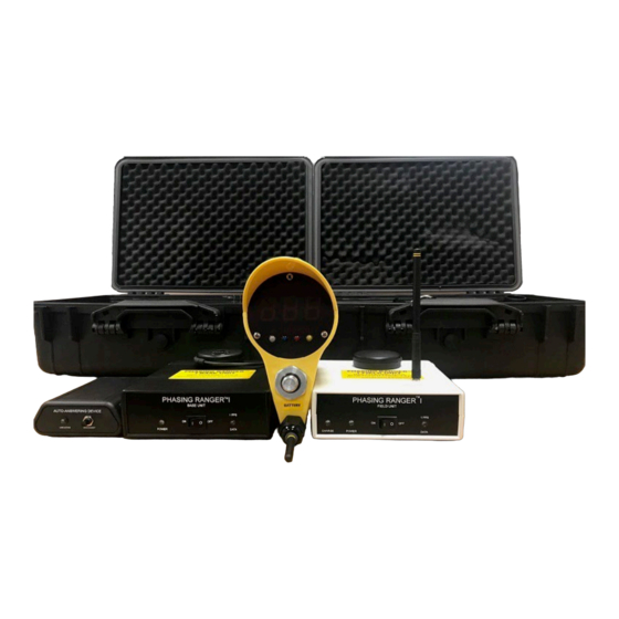
- Page 1 Phasing Ranger 2™ Long Distance Phasing System Operating Instructions Patent No. 6,617,840 and 6,734,658...
-
Page 2: Table Of Contents
Phase Angle Measurements Testing Phase Sequence FCC Compliance Information Statement Parts & Accessories Notes For Training, Support, or Any Questions Concerning the use of the Phasing Ranger 2 or the Information In This Manual Feel Free to call us at (803)786-4839... -
Page 3: Limitation Of Warranty And Liability
Bierer & Associates Inc. Bierer & Associates Inc. do not express or imply to be an insurer of these risks, and by purchasing or using this product you AGREE TO ACCEPT THESE RISKS. IN NO EVENT SHALL Bierer &... -
Page 4: Product Safety Information
PRODUCT SAFETY INFORMATION WARNING 1. Meter assembly, interconnect cable assembly, and live line tool adapters shall be considered non-insulating. Do not let live line tool fittings come in contact with energized or grounded conductors. The live line tool adapters, fittings, and handles supplied with meters shall not be used on any other devices. -
Page 5: Design And Function
The Receive Unit talks directly to the Meter Probe to provide the correct phase angle. The Phasing Ranger 2 is useable from 120/208 V to 800kV at a tested distance of 1000 miles. - Page 6 PD800W Meter Probe (DEG Position ONLY) DEG – Phase angle measurement in degrees for use on Secondary, URD and Overhead. Direct contact from 240V to 69kV (including capacitive test points). Non-contact from 69kV to 800kV. T – Tests basic meter function and displays the internal 9V battery voltage. 0 degree light - indicates an in-phase condition relative to send unit 120 degree light - indicates out-of-phase condition of 120 degrees.
-
Page 7: Meter Probe Set-Up And Testing
1. Turn the unit to the test position and verify a god battery voltage level. 2. Turn the selector switch back to URD position. 3. Turn on the known voltage source, Bierer offers several options, but we’ll be using the 3kV power supply and Handheld Power Supply for this. -
Page 8: Send Unit Set-Up And Testing
SEND UNIT SET-UP & TESTING: 1. Permanently place satellite receiver (GPS) where there is a clear view of the sky, i.e. a window sill (non-tinted), preferably outside on the building structure with a minimum distance of 16 inches from the wall. 2. -
Page 9: Receive Unit Set-Up And Testing
RECEIVE UNIT SET-UP & TESTING: WARNING See “Product Safety Information”, page 4. See “Inspection & Maintenance”, page 4. Place the Field Unit in a location where there is a clear view of the sky (dashboard of automobile is suitable). Turn switch to the ON position, both lights (Red Power and White 1PPS Data) should blink momentarily and then the red light (Power) should remain on. -
Page 10: Phase Angle Measurements
PHASE ANGLE MEASUREMENTS Direct Contact from 120/208V to 69kV including Capacitive Test Points WARNING See “Product Safety Information”, page 4. See “Inspection & Maintenance”, page 4. See “Send Unit Set-up and Testing”, page 8. See “Receive Unit Set-up and Testing”, page 9. Attach the Meter Probe to the appropriate length live line tool for the voltage being tested. - Page 11 3. Using the meter probe, bring the meter to minimum approach distance as described in OSHA standard 1910-269, table R-6. You can also use the Bierer Support Hooks. Use a 2 foot hook for voltages from 69kV to 300kV and use the 4 foot support hook for voltages above 300kV.
-
Page 12: Testing Phase Sequence
TESTING PHASE SEQUENCE WARNING See “Product Safety Information”, page 4. See “Inspection & Maintenance”, page 4. See “Send Unit Set-up and Testing”, page 8. See “Receive Unit Set-up and Testing”, page 9. Phase sequence will be either: (1 - 2 - 3) or (3 - 2 - 1) (A - B - C) or (C - B -A) Phase sequence is the order in which the voltages of a three phase system rise... -
Page 13: Fcc Compliance Information Statement
Report Number: B31202D2 Compliance Test Report Dates: 12/01/03 & 12/02/03 Responsible Party: Bierer & Associates, Inc. Address: 10730 Farrow Rd., Blythewood, SC 29016 Telephone: 803-786-4839 This equipment (Meter Probe) has been tested and found to comply with limits for a Class B, RF Receiver pursuant to Part 15 of the FCC rules. These limits are designed to provide reasonable protection against harmful interference in a residential installation. -
Page 14: Parts & Accessories
Bierer & Associates Inc. Manufacturing & Repair 10730 Farrow Rd. Blythewood SC 29016... -
Page 15: Notes
Notes_____________________________________________ __________________________________________________ __________________________________________________ __________________________________________________ __________________________________________________ __________________________________________________ __________________________________________________ __________________________________________________ __________________________________________________ __________________________________________________ __________________________________________________ __________________________________________________ __________________________________________________ __________________________________________________ __________________________________________________ __________________________________________________ __________________________________________________ __________________________________________________ __________________________________________________ __________________________________________________ __________________________________________________ __________________________________________________ __________________________________________________ __________________________________________________ __________________________________________________ __________________________________________________ __________________________________________________ __________________________________________________ __________________________________________________ __________________________________________________ __________________________________________________ __________________________________________________ __________________________________________________ __________________________________________________ __________________________________________________...
Need help?
Do you have a question about the Phasing Ranger 2 and is the answer not in the manual?
Questions and answers