Advertisement
Quick Links
JY997D36701E
FX
-2HC
3U
USER'S MANUAL
Manual Number
JY997D36701
Revision
E
Date
March 2019
This manual describes the part names, dimensions, mounting, wiring, and
specifications of the product. Before use, read this manual and the manuals of all
relevant products fully to acquire proficiency in handling and operating the product.
Make sure to learn all the product information, safety information, and precautions.
Store this manual in a safe place so that it can be taken out and read whenever
necessary. Always forward it to the end user.
Registration:
The company names, system names and product names mentioned in this manual
are either registered trademarks or trademarks of their respective companies.
In some cases, trademark symbols such as '
' or '
' are not specified in this manual.
Effective March 2019
Specifications are subject to change without notice.
Safety Precaution
(Read these precautions before use.)
This manual classifies the safety precautions into two categories:
and
.
Indicates that incorrect handling may cause hazardous
conditions, resulting in death or severe injury.
Indicates that incorrect handling may cause hazardous
conditions, resulting in medium or slight personal injury
or physical damage.
Depending on the circumstances, procedures indicated by
also cause severe injury.
It is important to follow all precautions for personal safety.
Associated Manuals
Manual name
Manual No.
Description
FX
3U
Series
JY997D16501
Explains the FX
3U
Series PLC
User's Manual
MODEL CODE:
specifications for I/O, wiring,
- Hardware Edition
09R516
installation, and maintenance.
FX
3UC
Series
JY997D28701
Explains the FX
3UC
Series PLC
User's Manual
MODEL CODE:
specifications for I/O, wiring,
- Hardware Edition
09R519
installation, and maintenance.
FX
/FX
/FX
/
3S
3G
3GC
Describes FX
3S
/FX
3G
/FX
FX
/FX
Series
JY997D16601
3U
3UC
FX
3UC
Series PLC programming for
Programming Manual
MODEL CODE:
basic/applied instructions and
- Basic & Applied
09R517
devices.
Instruction Edition
MELSEC iQ-F FX5U
JY997D55301
Explains the FX5U PLC
User's Manual
MODEL CODE:
specifications for I/O, wiring,
(Hardware)
09R536
installation, and maintenance.
MELSEC iQ-F FX5UC
JY997D61401
Explains the FX5UC PLC
User's Manual
MODEL CODE:
specifications for I/O, wiring,
(Hardware)
09R558
installation, and maintenance.
How to obtain manuals
For product manuals or documents, consult with the Mitsubishi Electric dealer
from who you purchased your product.
Certification of UL, cUL standards
The following product has UL and cUL certification.
UL, cUL File Number:E95239
Models:
MELSEC FX
3U
series manufactured
from December 1st, 2009
FX
3U
-2HC
Compliance with EC directive (CE Marking)
This note does not guarantee that an entire mechanical module produced in
accordance with the contents of this note will comply with the following standards.
Compliance to EMC directive and LVD directive for the entire mechanical module
should be checked by the user / manufacturer. For more details please contact the
local Mitsubishi Electric sales site.
Requirement for Compliance with EMC directive
The following products have shown compliance through direct testing (of the identified
standards below) and design analysis (through the creation of a technical construction
file) to the European Directive for Electromagnetic Compatibility (2014/30/EU) when
used as directed by the appropriate documentation.
Attention
This product is designed for use in industrial applications.
Type:
Programmable Controller (Open Type Equipment)
Models:
MELSEC FX
series manufactured
3U
from December 1st, 2009
FX
3U
-2HC
Standard
EN61131-2:2007
Compliance with all relevant aspects of the standard.
Programmable controllers
EMI
- Equipment requirements
• Radiated Emission
and tests
• Conducted Emission
EMS
• Radiated electromagnetic field
• Fast transient burst
• Electrostatic discharge
• High-energy surge
• Voltage drops and interruptions
• Conducted RF
• Power frequency magnetic field
Caution for EC Directive
Installation in Enclosure
Programmable controllers are open-type devices that must be installed and used
within conductive control cabinets. Please use the programmable controller while
installed within a conductive shielded control cabinet. Please secure the cabinet
door to the control cabinet (for conduction). Installation within a control cabinet
greatly affects the safety of the system and aids in shielding noise from the
programmable controller.
1. Outline
1.1 Outline
The hardware high-speed counter block is a 2-channel high-speed counter. It is a
special function block for the FX
/FX
/FX5U/FX5UC PLC.
3U
3UC
1.2 Major Features of the FX
-2HC
3U
may
Differential-Line-Driver (AM26C31 or equivalent) and open collector output
encoders are available for the FX
3U
-2HC.
The FX
3U
-2HC has two outputs per channel. When the counter value coincides with
an output compare value, the appropriate output is set ON. The output transistors
are individually isolated to allow either sink or source connection methods.
Various counter modes, such as 1-phase or 2-phase, 16-bit or 32-bit modes, can be
selected using commands in the sequence program. Allow the FX
run only after setting these mode parameters.
1.3 Incorporated Items
Verify that the following product and items are included in the package:
Included Items
FX
-2HC
3U
3GC
/FX
3U
/
Special unit/block No. label
Dust proof protection sheet
Manuals [Japanese version]
Manuals [English version] (This manual)
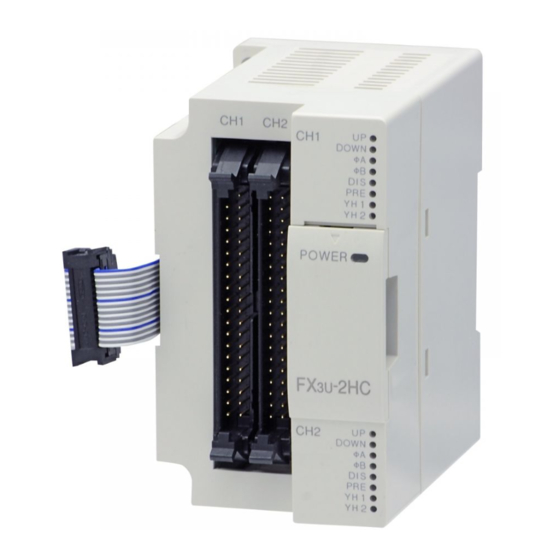
1.4 External Dimensions, Part Names, and Terminal Layout
[2]
[3] [4]
2-φ4.5 mounting holes
[1]
[9]
[8]
9 (0.36")
4 (0.16")
87 (3.43")
55 (2.17")
Weigh: Approx. 0.2 kg (0.44 lbs)
No.
Direct mounting hole: 2 holes of
[1]
Used when attaching FX
3U
Extension cable (PLC side)
[2]
Used to connect this special function block to the FX
extension block.
[3]
CH1 connector
[4]
CH2 connector
Status LED (the upper side: CH1, the lower side: CH2)
POWER
Power LED
(Green)
UP (Red)
Up count LED
DOWN (Red)
Down count LED
Remark
A phase input LED
A (Red)
[5]
B (Red)
B phase input LED
DIS (Red)
DISABLE input LED T h e r e s p e c t i v e L E D i s O N / O F F
PRE (Red)
PRESET input LED
YH1 (Red)
YH1 output LED
YH2 (Red)
YH2 output LED
[6]
Top cover
Extension connector (Extension side)
[7]
Used to connect a FX
3U
block. Remove top cover for connecting.
[8]
DIN rail mounting hook
[9]
DIN rail mounting groove (DIN rail: DIN46277, 35mm (1.38") width)
FX
-2HC connector arrangement
3U
CH1
A24+
A12+
Phase A
A5+
A-
input
B24+
B12+
Phase B
input
B5+
B-
PRESET
P24+
P12+
input
P5+
P-
3U
-2HC unit to
XD24
XD5
DISABLE
input
COMD
YH1 output
YH1+
YH1-
YH2 output
YH2+
YH2-
1 Unit
1 Sheet
1 Sheet
1 manual
1 manual
2. Installation, Connect to the PLC
INSTALLATION
PRECAUTIONS
Without top cover
Make sure to cut off all phases of the power supply externally before attempting
[5]
installation or wiring work.
Failure to do so may cause electric shock or damage to the product.
INSTALLATION
[5]
PRECAUTIONS
[6]
Use the product within the generic environment specifications described in PLC
main unit manual.
[5]
Never use the product in areas with excessive dust, oily smoke, conductive dusts,
corrosive gas (salt air, Cl
2
impacts, or expose it to high temperature, condensation, or rain and wind.
[7]
If the product is used in such conditions, electric shock, fire, malfunctions,
deterioration or damage may occur.
INSTALLATION
Name
PRECAUTIONS
4.5 (0.18") (mounting screw: M4 screw)
Do not touch the conductive parts of the product directly.
-2HC directly.
Doing so may cause device failures or malfunctions.
Install the product on a flat surface.
3U
/FX
3UC
main unit or an
If the mounting surface is rough, undue force will be applied to the PC board,
thereby causing nonconformities.
When drilling screw holes or wiring, make sure cutting or wire debris does
not enter the ventilation slits.
Failure to do so may cause fire, equipment failures or malfunctions.
Be sure to remove the dust proof sheet from the PLC's ventilation port when
installation work is completed.
ON when the 5V power supply is
Failure to do so may cause fire, equipment failures or malfunctions.
normally supplied from the PLC.
Connect extension cables securely to their designated connectors.
The respective LED is ON according
Loose connections may cause malfunctions.
to up/down count direction of the
counter.
2.1 Mounting
The respective LED is ON (flicker)
The product is mounted by the following method.
according to ON/OFF of
A and
B
DIN rail mounting
input.
Direct mounting (mounting screw: M4 screw)
For further information on installation arrangements, refer to the following manuals.
according to ON/OFF of PRESET and
DISABLE input.
T h e r e s p e c t i v e L E D i s O N / O F F
according to status of YH1 and YH2
2.1.1
DIN Rail Mounting
output.
The product can be mounted on a DIN rail
(DIN46277, 35mm (1.38") width).
1) Fit the upper edge of the DIN rail mounting
extension block to the right of this special function
groove (fig. A) onto the DIN rail.
2) Press the product against the DIN rail.
- An interval space of 1 to 2 mm (0.04" to
0.08") between each unit is necessary.
CH2
A24+
A12+
2.1.2
Direct Mounting (mounting screw: M4 screw)
A5+
A-
The product can be installed directly with screws.
Refer to the External Dimensions (section 1.4) for the product's mounting hole
pitch information.
B24+
B12+
An interval space between each unit of 1 to 2 mm (0.04" to 0.08") is necessary.
B5+
B-
2.2 Connection to the PLC
P24+
P12+
A maximum of eight
P5+
P-
right side of the powered extension unit/block. A unit number of No.0 to No.7 is
assigned based on the order in which special function units/blocks are attached to
Notch
Notch
the main unit.
For connection to an FX
XD24
XD5
FX
-CNV-IF or FX
2NC
COMD
For connection to an FX5U or FX5UC PLC, an FX5-CNV-BUS or FX5-CNV-BUSC
is required.
YH1+
YH1-
*1 Up to seven special function units/blocks in total can be connected to the
FX
3UC
YH2+
YH2-
blocks begins with No.1.
*2 Up to two special function units/blocks in total can be connected to the
FX5U or FX5UC PLC. Unit numbers assigned to special function units/
blocks begins with No.2.
For further information on installation arrangements, refer to the following manuals.
3. Wiring
WIRING
PRECAUTIONS
Make sure to cut off all phases of the power supply externally before
attempting installation or wiring work.
Failure to do so may cause electric shock or damage to the product.
When drilling screw holes or wiring, make sure cutting or wire debris does
not enter the ventilation slits.
Failure to do so may cause fire, equipment failures or malfunctions.
, H
S, SO
, or NO
), flammable gas, vibration or
2
2
2
Refer to the FX
3U
Series User's Manual - Hardware Edition.
Refer to the FX
Series User's Manual - Hardware Edition.
3UC
Refer to the MELSEC iQ-F FX5U User's Manual (Hardware).
Refer to the MELSEC iQ-F FX5UC User's Manual (Hardware).
1)
A
2)
*1*2
FX
3U
-2HC(s) are connectable with the main unit or the
Series PLC or FX
Series PLC extension block, an
3UC
2NC
-1PS-5V is required.
3UC
-32MT-LT(-2) PLC. Unit numbers assigned to special function units/
Refer to the FX
3U
Series User's Manual - Hardware Edition.
Refer to the FX
Series User's Manual - Hardware Edition.
3UC
Refer to the MELSEC iQ-F FX5U User's Manual (Hardware).
Refer to the MELSEC iQ-F FX5UC User's Manual (Hardware).
Advertisement

Related Manuals for Mitsubishi Electric MELSEC-F FX3U


Summary of Contents for Mitsubishi Electric MELSEC-F FX3U
- Page 1 Failure to do so may cause electric shock or damage to the product. How to obtain manuals Make sure to cut off all phases of the power supply externally before For product manuals or documents, consult with the Mitsubishi Electric dealer INSTALLATION attempting installation or wiring work.
-
Page 2: Specifications
3.2.2 PNP output encoders 3.2.5 YH1, YH2 output wiring [Source wiring] 4.3 Performance Specifications WIRING PRECAUTIONS Encoder (PNP) Item Specification 24V DC -2HC Make sure to observe the following precautions in order to prevent any YH1+ [A24+],[B24+], 24V DC10%, +24V [P24+] 8mA or less... - Page 3 5. Buffer Memories (BFM) 5.2.2 [BFM #1 (CH1), #41 (CH2)] Output occurs when the current value becomes equal to the compare value but DOWN/UP command Count modes 32 bits 16 bits Reference only if b1 and b2 of BFM #4, #44 are ON. Once an output is set, it remains ON When using the 1-phase 1-input counter [Software UP/DOWN] (counter mode: K10, 5.1 Buffer memory List until it is reset by b9 or b10 of BFM #4, #44.
- Page 4 This manual confers no industrial property rights or any rights of any other kind, Bit N0. Error Status M8000 nor does it confer any patent licenses. Mitsubishi Electric Corporation cannot be FNC 79 Set when the counter mode (BFM #0, K4M10...
-
Page 5: Installation
Failure to do so may cause electric shock or damage to the product. How to obtain manuals Make sure to cut off all phases of the power supply externally before For product manuals or documents, consult with the Mitsubishi Electric dealer INSTALLATION attempting installation or wiring work. - Page 6 This manual confers no industrial property rights or any rights of any other kind, Bit N0. Error Status M8000 nor does it confer any patent licenses. Mitsubishi Electric Corporation cannot be FNC 79 Set when the counter mode (BFM #0, held responsible for any problems involving industrial property rights which may...
Need help?
Do you have a question about the MELSEC-F FX3U and is the answer not in the manual?
Questions and answers