
Subscribe to Our Youtube Channel
Related Manuals for Cooper & Hunter CHV-05SDLSP


Summary of Contents for Cooper & Hunter CHV-05SDLSP
- Page 1 VRF INDOOR UNIT CHV-05SDLSP,CHV-07SDLSP LOW HEIGHT CEILING CHV-09SDLSP,CHV-12SDLSP DUCTED CHV-15SDLSP,CHV-17SDLSP TYPE CHV-19SDLSP,CHV-22SDLSP CHV-24SDLSP ORIGINAL INSTRUCTIONS...
- Page 3 IMPORTANT NOTICE Signal words (DANGER, WARNING, CAUTION, and NOTE) are used to indicate hazard seriousness. Definitions of the hazard levels are provided below with respective signal words. This manual should be considered as a permanent part of the air conditioning equipment. Please keep it properly. ●...
- Page 5 ● o not use an spra s suc as insecticide lac uer air spra or ot er flamma le gases it in appro imatel meter from t e s stem. ● If t e eart lea age rea er is fre uentl acti ated please stop t e s stem and contact our local dealer or r u or ser ices.
-
Page 7: Table Of Contents
a le of ontents ection peration Manual afet ummar nit escription art ame . Indoor nit efore peration utomatic ontrol rou les ooting . If rou le till Remains peration ot ooling or eating is is ot normal ection Installation & Maintenance Manual afet ummar ecessar... -
Page 9: Ection Peration Manual
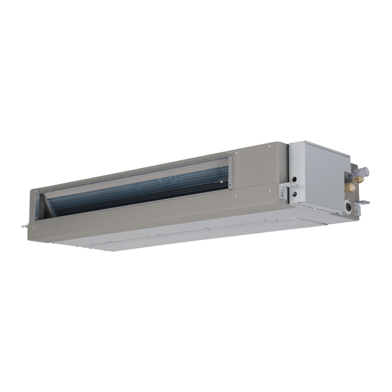
Section 1 Operation Manual 1. Safety Summary Table 2.1 Capacities of Indoor Units Indoor nit ominal apacit ! ● Do not have the indoor unit or outdoor unit exposed to water. All these parts are designed with electronic components that may cause short circuit when exposed to ucted water. - Page 10 Fig. 3.1 Ducted Type Indoor Unit Models 05~17 Models 19~24 No. Name Name Centrifugal Fan Drain Piping Base Motor Float Switch Heat Exchanger Drain Pan istri utor Air Outlet Filter Air Inlet Electronic Expansion Valve Drain Pump Electric Box Coupling (Models 19~24) Refrigerant Gas Pipe Connection(φa Flare) Filter Screen Refrigerant Liquid Pipe Connection(φb Flare)
-
Page 11: Efore Peration
4. Before Operation Oil Return Operation When an indoor unit is out of service for more than 2 hours during refrigeration, it will run for a few minutes The units that have been left unused for a long period of automatically to prevent the detention of refrigeration oil time shall be electrified for more than 4 hours before in the indoor unit in stopped state. -
Page 12: Rou Les Ooting
6. Troubleshooting ! When overflow of drain water from the indoor unit occurs, stop the operation and contact your contractor. When you smell or see white smoke coming from the unit, turn OFF the main power supply and contact your contractor. -
Page 13: Ecessar Ools And Instrument For Installation
Section 2 Installation & Maintenance Manual 1. Safety Summary ! ! Please don't perform installation works such as Do not install the indoor unit, outdoor unit, wired refrigerant piping connection, drain pipe connection, control and cable within approx. 39-13/32 inch. from and electrical wiring connection. -
Page 14: Ransportation And Andling
3. Transportation and Handling 4.2 Initial Check Install the indoor unit with a proper clearance 3.1 Transportation Transport the product as close to the installation location around it for operation and maintenance a po before unpacking. working space, as shown in Fig. 4.1. !... -
Page 15: Installation And Repair Of Ilter Creen
4.4 Indoor Unit Installation Pay attention to the following points when the indoor unit is installed in a hospital or other facilities where there are electronic waves from medical equipment, etc.: 4.4.1 Suspension Bolts (A) Do not install the indoor unit where the electromagnetic wave is directly radiated to the electric box, wired control (1) Decide upon appropriate mounting position and cable or wired control. - Page 16 4.4.2 Suspension Bolt and Pipe (1) How to Install Suspension Bolt and Nut Mount nuts to the four bolts as shown in Fig. 4.6. Connection Points (1) Indicate the location of suspension bolt, and the Unit: in. connection points of refrigerant pipe and drain pipe. (2) Installation dimensions are shown in Fig.
-
Page 17: Refrigerant Iping Or
5. Refrigerant Piping Work 4.4.4 Leveling of Indoor Unit (1) Check to ensure the top surface is level, and measure the max. top surface inclination degree. ! Use refrigerant R410A in the refrigerant cycle. Do not charge oxygen, acetylene or other flammable and poisonous gases into the refrigerant cycle when performing a leakage test or an air- tight test. -
Page 18: Iping Onnection
5.2 Piping Connection (2) As shown in Fig. 5.4, two spanners shall be used for tightening the nut. (1) Piping connection points are shown in Figs. 5.1 and 5.2. Unit: in. 3-35/64 Refrigerant Refrigerant 2-19/32 6-35/64 Gas Pipe Liquid Pipe Pipe Size (inch(mm)) Tightening Torque (ft.·lbs(N.m)) 1/4(6.35) -
Page 19: Rain Iping
! ! Excessive and inadequate refrigerant is a leading cause Where the relative humidity of air inlet or ambient air of system anomaly. Please inject the right amount of exceeds 80%, an auxiliary drain pan shall be fabricated at refrigerant. installation site and placed under the indoor unit, as shown in Fig. -
Page 20: Lectrical Iring
7.1 General Check 7. Electrical Wiring Make sure that the field-selected electrical components (main power switches, circuit breakers, wires, conduit connectors and wire terminals) have been properly ! selected according to the electrical data given in "Technical Catalog I". Make sure the components comply Turn OFF the main power switch to the indoor unit and with National Electrical Code (NEC). -
Page 21: Est Run
Wire Clamp 8. Test Run The debugging shall be performed as per the Installation & Maintenance Manual. Terminal Block (TB) ! The machine can't be started unless all check points are checked and ascertained. Wired Remote (A) Check to make sure the terminal resistance to ground Control Enlarged View of exceeds 1MΩ;... -
Page 22: Ield Peration
10. Field Operation 10.1 Specifications of Field Connected Power Cord Electrical Parameters and Power Cord Size of Indoor Unit Power Cord Signal Wire Indoor Unit Capacity (kBtu/h) Power Supply Max. Current Specifications Specifications (AWG) (AWG) 05~07 0.47A 0.64A 09~12 208/230V~ 15~17 0.74A 14(2.5mm... -
Page 23: Etting Of I Itc
10.2 Setting of DIP Switch Refrigerant System Setting DSW5 (Tens Digit) RSW2 (Units Digit) Ex.) Set system No. 5 Insert a flat head (1) DIP switch must be set with power sources of the indoor screw driver into the Setting Position and outdoor units in OFF state. - Page 24 The om an is ommitted to ontinuous rodu t im ro ement. We reser e the right therefore to alter the rodu t information at an time and without rior announ ement. 08.2022...
Need help?
Do you have a question about the CHV-05SDLSP and is the answer not in the manual?
Questions and answers