
Subscribe to Our Youtube Channel
Related Manuals for Cooper & Hunter CHV-07SDHSP


Summary of Contents for Cooper & Hunter CHV-07SDHSP
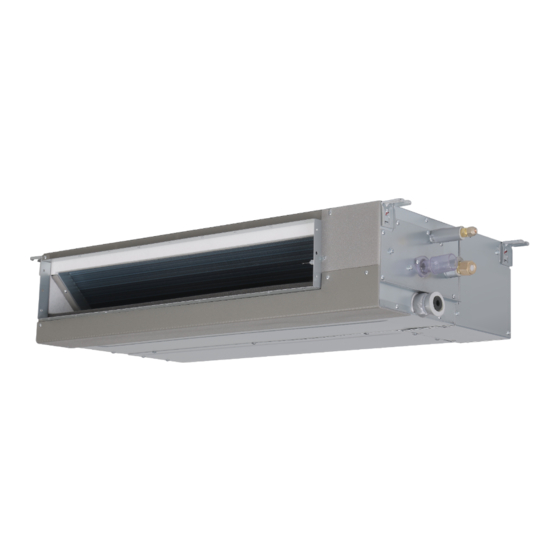
- Page 1 VRF INDOOR UNIT CHV-07SDHSP CHV-09SDHSP CHV-12SDHSP CHV-15SDHSP CHV-19SDHSP CEILING CHV-24SDHSP DUCTED CHV-30SDHSP TYPE CHV-38SDHSP CHV-48SDHSP CHV-54SDHSP ORIGINAL INSTRUCTIONS...
- Page 3 Our company Our company International Organization for Standardization: (ISO 5149 or European Standard, EN 378). our company. Refer to Installation & Maintenance Manual of outdoor unit for temperature operation range.
- Page 4 Our company's our company's...
- Page 5 8. Filter Cleaning Installation of the Filter Section2 Installation & Maintenance Manual...
- Page 7 3.3ft.(1m) Ground Fault Circult Interrupter(GFCI) The appliance is not to be used by children or unless they have been given supervision or instruction concerning use of the appliance by a person responsible for their safety. Children should be supervised so that they do not play with the appliance.
- Page 8 F(16 90 F(32...
-
Page 9: Automatic Control
122 F 122 F Automatic Control Regarding the instructions of Wired Remote Control Switch or Wireless Remote Control Switch read the operation manual attached to the control switch. -
Page 10: Troubleshooting
Troubleshooting 80 F (27 C)/80% R.H), Self-clean: During self-cleaning, the sound of sputter may be heard, which is a normal physical phenomena, and will disappear after cleaning. -
Page 11: Installation Of The Filter
Step 1 approximately 104 F( Remove two screws from the small plate next to the electric box. Screws Installation of the Filter Step 2 The installation method is contrary to the disassembly method But Install air Take out the small plate from the indoor unit. filter according to arrow direction. - Page 12 9.8ft.(3m) R410A possible...
- Page 13 8.2ft.(2.5m)
- Page 14 Unit: in. Electrical Box Service Access Door (≥ 17-23/32) In case that the ceiling board can 0.026lb/ft (0.42kg/m³ not be detected for servicing, Rear Side prepare a service access door below the indoor unit for removing the indoor unit. 0.026lb/ft 0.42kg/m Front Side (5-1/8)
- Page 15 Unit: in. (mm) 27-9/16 25-19/32 28-11/32 25-19/32 (700) (650) (720) (650) 37-1/4 35-7/16 28-11/32 25-19/32 (946) (650) (720) (650) 45-9/32 43-5/16 31-1/2 28-5/8 (1150) (110) (800) (727) 57-3/32 55-1/8 31-1/2 28-5/8 (1450) (1400) (800) (727) Suspension Bracket Nut & Washer...
- Page 16 Unit: in. (mm) (0~5mm) 0 13/64in. Static Pressure Voltage Model in.W.G.(Pa) 0. 2 /0. 0 /1 0) 230V 2 2 08/ 0.20 /0. 0 /200) (0): or S pm nt 17-23/32 in. ×17-23/32 in.
- Page 17 Dimension Model 7-11/64 8-47/64 9-11/16 12-41/64 14-27/32 29/32 07 24 (182) (222) (246) (321) (377) (23) 5-29/32 7-31/64 10-5/8 13-37/64 15-25/32 55/64 30 54 (150) (190) (270) (345) (401) (22) Unit: in.(mm) Flaring Dimension Perform the flaring work as shown below. Unit: in.(mm) Diameter -1/64(0.4)
- Page 18 1-1/4in. - upp c amp Unit: in. (mm) Optional pump Drain Piping (PVC Tube, VP25) (Field-Supplied) Suspension Bracket 1/25 to 1/100 Down-Slope (Field-Supplied) 2-9/32(58) Elbow Pipe (VP25) (Field-Supplied) Lift Piping for Drain-Up (PVC Tube, VP25) (Field-Supplied) Drain Hose (L: 11-13/16 (300)) Indoor Unit (Accessory) Drain...
- Page 19 All electrical work must be done as outlined in this manual and in accordance with this manual. Substandard work can result in fire and damage to the unit. Use specified cables between units and choose the cables correctly. If not, an electrical shock or fire may occur.
- Page 20 Enlarged View of P Part Terminal Block (TB) Wiring Communication Wired Power Cord Cable Remote Control 208 230V~60Hz Wire View from B 55/ 4 in. (φ22.2mm) Conduit Hole F(90 Connecting Hole for Connecting Hole for Communication Cable Power Supply Wiring...
- Page 21 Line This equipment can be installed with a Ground Fault Circuit Interrupter (GFCI), which is a recognized measure for added protection to a properly grounded unit. Install appropriate sized breakers /fuses / overcurrent protection switches and wiring in accordance to local, state and NEC codes and requirements. The equipment installer is responsible for understanding and abiding by applicable codes and requirements.
- Page 22 Refrigerant System Setting (1) DIP switch must be set with power sources of the indoor DSW5(Setting 0~63) Ex.) Set system No. 5 and outdoor units in OFF state. Otherwise, the settings are invalid. (2) The location of DIP switch is shown in the figure below. DSW5 are set to "0"...
- Page 23 pp n Compar on a o 8421 Co D c ma :The current position is set to OFF :The current position is set to ON...
- Page 24 The Company is committed to continuous product improvement. We reserve the right, therefore, to alter the product information at any time and without prior announcement. 08.2022 V00...
Need help?
Do you have a question about the CHV-07SDHSP and is the answer not in the manual?
Questions and answers