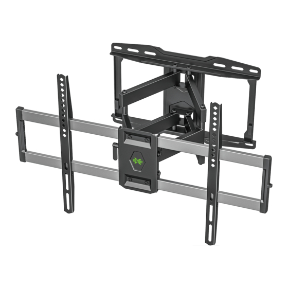
Summary of Contents for USX-MOUNT XML012-01
- Page 1 XML012-01 INSTRUCTION MANUAL For 47-84" TV If you have any questions along the way, just give us a call 1-800-460-0956 or mail to customerservice@x-mount.com. We’re ready to help! USA-A1...
- Page 2 Before getting started, let’s check below lists to make sure it is just right for you! MAX:600mm/23.62" (MIN:200mm/7.87") Check your TV VESA is within No? This mount is NOT compatible. Min and Max size MAX:400mm/15.74" (MIN:100mm/3.94") Yes? Perfect ! CAUTION: DO NOT exceed the maximum weight Does your TV No? Perfect –...
- Page 3 TV INTERFACE 200mm 15mm [7.87in] [0.59in] 400mm [15.75in] 600mm [23.62in] WALL PLATE TOP VIEW - EXTENDED SIDE VIEW - EXTENDED 412.1mm [16.22in] [0.35in] +5° 236mm 421mm [9.29in] [16.57in] -15° 175.7mm [6.92in] FULLY ASSEMBLED MOUNT TOP VIEW - RETRACTED SIDE VIEW - EXTENDED 697mm [27.44in] 63mm...
- Page 4 WARNING: This product contains small items that could be a choking hazard if swallowed. Before starting assembly, verify all parts are included and undamaged. If any parts are missing or damaged, do not return the damaged item to your dealer; contact Customer Service.
- Page 5 Parts and Hardware for STEP 2 Wall Plate Unit M6x16mm Bolt Lag Bolt Allen Key Mounting template Contact us at telephone 1-800-460-0956 (USA) or mail to customerservice@x-mount.com. to have these additional pieces shipped directly to you. Concrete Wall Anchor 4pcs Velcro x3 16"(406.4mm) 8"(203.2mm)
- Page 6 1-1 Select TV Screws...
- Page 7 1-2 Figure out the suitable position of brackets HIGH MOUNTING HOLES LOW MOUNTING HOLES TV BRACKETS MUST BE LEVEL INSTALL UP/DOWN IF NEEDED...
- Page 8 1-4 Attach the TV Plate 1-3 Need Spacer? No, choose suitable screws and washers. Yes, choose suitable screws, washers and spacers. Tips: If you need to combine M6/M8(c/e/f) screws with 2.5mm spacers( i ), you have to remove the inner circle.
- Page 9 CAUTION: Avoid potential personal injury or property damage! ● Drywall covering the wall, must not exceed 5/8 in. (16 mm) ● Minimum wood stud size: common 2 x 4 in. (51 x 102 mm) nominal 1½ x 3½ in. (38 x 89 mm) ●...
- Page 10 3. Drill pilot holes using a 7/32 in. (5.5 mm) diameter drill bit. IMPORTANT: Pilot holes must be drilled to a depth of 2.5 in. (64 mm). Be sure to drill into the center of the studs. 4. Install wall plate using four lag bolts .
- Page 11 CAUTION: Avoid potential personal injury or property damage! ● Mount the wall plate assembly directly onto the concrete surface ● Minimum solid concrete thickness: 8 in. (203 mm) 1. Position the mounting template on the wall at your desired height. Level the wall plate and mark the hole locations.
- Page 12 3. Insert four anchors. CAUTION: Be sure the anchors are seated flush with the concrete surface. 4. Insert wall plate using four lag bolts .Tighten the lag bolts only until they are pulled firmly against the wall plate. CAUTION: Improper use could reduce the holding power of the lag bolt. DO NOT over-tighten the lag bolts.
- Page 13 Before hanging TV, please try to pull the mount to make sure that it has been assembled on the wall tightly.
- Page 14 Hang TV/bracket assembly onto wall plate, wrap clips on bracket around extension arms and tighten them using bolts...
- Page 15 5-1 TV leveling adjustment (±4°): Loosen 4 leveling bolts on the rear of TV plate by maximum 2 turns, adjust to level, and retighten to secure. ±4° Loosen Tighten...
- Page 16 5-2 Tilting angle adjustment (+5°/-15°) : Loosen handle and tilting bolt, adjust TV to your desired position, then tighten handle and tilting bolt. Put the handle level when finish. Level Handle Tilting bolts Tilting bolts +5° -15° Tighten Tighten Loosen Loosen +5°...
- Page 17 5-3 Cables manage: Manage TV cables orderly and guide them through the velcros. Velcro...


Need help?
Do you have a question about the XML012-01 and is the answer not in the manual?
Questions and answers