Table of Contents
Advertisement
YF120vRX24-SB
24" DUAL-STAGE CORDLESS
SNOW BLOWER
OWNER'S MANUAL
Our Customer Service staff is ready to provide assistance.
In the case of a damaged or missing part, most replacement parts ship from our facility.
For immediate help with assembly, or for additional product information, email support@
MerotecUSA.com or call 866-902-9690 M-F 8:30am – 5:00pm ET. More information can be
found on www.YardForceUSA.com.
SAVE THIS MANUAL FOR REFERENCE
You will need this manual for safety instructions, operating
procedures, and Warranty. The original sales receipt is
required for warranty service.
YF120vRX24-SB
Advertisement
Table of Contents

Related Manuals for Yard force YF120vRX24-SB

Summary of Contents for Yard force YF120vRX24-SB
- Page 1 YF120vRX24-SB YF120vRX24-SB 24" DUAL-STAGE CORDLESS SNOW BLOWER OWNER'S MANUAL Our Customer Service staff is ready to provide assistance. In the case of a damaged or missing part, most replacement parts ship from our facility. For immediate help with assembly, or for additional product information, email support@ MerotecUSA.com or call 866-902-9690 M-F 8:30am –...
-
Page 2: Table Of Contents
YF120vRX24-SB Original Instructions TABLE OF CONTENTS Safety Instructions………………..…..…..…..…..…..…..…..…..…..3 Description of Symbols…………..…..…..…..…..…..…..…..…..…...7 Parts List…………..…..…..…..…..…..…..…..…..…....…..…..8 Technical Specifications………..…..…..…..…..…..…..…..…..…....11 Assembly……………..…..…..…..…..…..…..…..…..…....…....12 Operation…………………..…..…..…..…..…..…..…..…..…....15 Maintenance and Storage………..…..…..…..…..…..…..…..…..…..24 Troubleshooting………… ..…..…..…..…..…..…..…..…..…..…..28 Warranty……………..…..…..…..…..…..…..…..…..…....…..30... -
Page 3: Safety Instructions
SAFETY INSTRUCTIONS WARNING! To reduce the risk of injury, the user must read and understand the owner's manual before using this product. WARNING! READ AND UNDERSTAND ALL INSTRUCTIONS. Failure to follow all instructions listed below and on the machine could result in electric shock, fire, serious personal injury and/or death. - Page 4 SAFETY INSTRUCTIONS sleds, boards, wires, and other foreign objects. • Do not operate the equipment without wearing adequate winter garments. Avoid loose-fitting clothing that can get caught in moving parts. Wear footwear that will improve footing on slippery surfaces. • Never attempt to make any adjustments while the motor is running (except when specifically recommended by manufacturer).
- Page 5 2. Before using battery charger, read all instructions and cautionary markings on battery charger, battery, and product using battery. 3. To reduce the risk of injury, charge only YARD FORCE Y0L120BAT2.5 120V Li-ion battery pack using Y0L120CGR. 4. TO REDUCE THE RISK OF FIRE, ELECTRIC SHOCK, DEATH, OR SERIOUS PERSONAL...
- Page 6 SAFETY INSTRUCTIONS • This manual contains important safety and operating instructions for the charger. Refer to them frequently and use them to instruct others who may use this product. If you loan someone this product, loan them these instructions also to prevent misuse of the product and possible injury.
-
Page 7: Description Of Symbols
DESCRIPTION OF SYMBOLS The following symbols are used on the product and in this manual to alert the operator of potential safety hazards. Read them carefully, and understand their meaning. DANGER! Indicates an imminently hazardous situation which, if not avoided, will result in death or serious injury. -
Page 8: Parts List
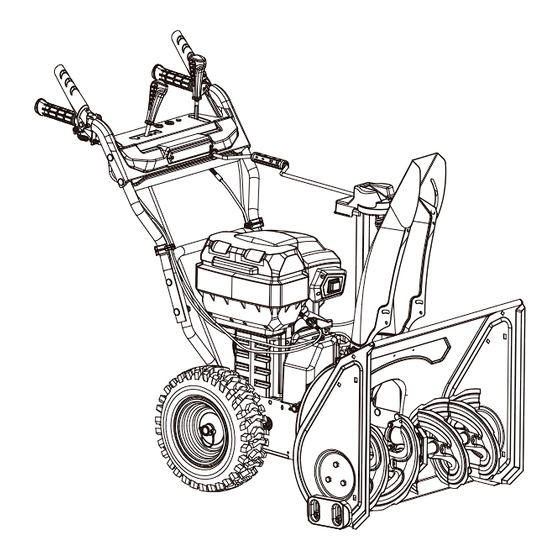
PARTS LIST KNOW YOUR SNOW BLOWER (See Fig.1) Fig. 1 12. Chute Rotation Bar LED Headlight 13. Auger Control Trigger Lower Handle 14. Heated Grip Battery Compartment 15. Speed Shift Handle On/Off Switch 16. Chute Deflector Handle Wheel 17. Drive Control Trigger Skid Shoe 18. - Page 9 PARTS LIST WARNING: The safe use of this product requires an understanding of the information on the product and in this operator’s manual as well as a knowledge of the project you are attempting. Before use of this product, familiarize yourself with all operating features and safety rules. On/Off Switch The On/Off switch must be pressed down before the motor can be started.
- Page 10 PARTS LIST PARTS LIST Two people should grasp the lower handle and the front part of the product at the same time and carefully lift the tool up and out of the carton. Remove any other accessories from the carton. Make sure that all items listed in the packing list are included.
-
Page 11: Technical Specifications
TECHNICAL SPECIFICATIONS Voltage 120V Clearing Width 24 in Intake Height 21 in Throwing Distance Up to 40 ft. Wheel Size 13 in Operating Temperature -4°F to 50°F(-20°C to 10°C) Storage Temperature 32°F to 113°F(-0°C to 45°C) Snow Blower Weight 119 lbs (54 kg) (Without battery and charger) -
Page 12: Assembly
ASSEMBLY WARNING: To prevent accidental starting that could cause serious personal injury, always remove the battery pack(s) from the tool when assembling parts. WARNING: If any parts are damaged or missing, do not operate this product until the parts are replaced. - Page 13 ASSEMBLY 2. Attach the auger drive control cable to the cable clamp located on the belt cover (see Fig. 4). Fig. 4 TO ASSEMBLE THE SPEED SHIFT ROD (See Fig. 5&6) 1. Remove the cotter pin from the bottom plate of the speed shift handle. (Fig. 5) 2.
- Page 14 ASSEMBLY TO INSTALL THE SNOW DISCHARGE CHUTE ASSEMBLY WARNING: Never operate the snow blower without the complete discharge chute in place. WARNING: Use the chute rotation handle to make sure that the chute rotates properly and that the discharge opening never crosses the operator controls. 1.
-
Page 15: Operation
OPERATION APPLICATION You may use this product for purpose listed below: Removing snow from areas such as driveways and sidewalks. Control Panel Fig. 14 Speed Shift Handle Set the speed shift handle into any position to control speed and direction. See Figure 14. - Page 16 OPERATION Move the handle (Fig.17 B) forward or backward to adjust the deflector. Fig. 17 Clean-Out Tool WARNING: Never use your hands to clear a clogged chute assembly. Shut off machine and remain behind handles until all moving parts have stopped before unclogging. The chute clean-out tool is fastened to the top of the auger housing with a mounting clip.
- Page 17 OPERATION 4. Insert the other battery pack into the other battery compartment in the same way. 5. To remove the battery pack, depress the battery release latch to release the battery pack, and then lift it out of the compartment (Fig. 19). 6.
- Page 18 OPERATION To Stop the Snow Blower 1. Fully release the auger control trigger. 2. Set the on/off switch to the "off" position. Fig. 21 Fig. 20 Auger control trigger Variable-Speed Self-Propel System (Fig.22) Fig. 22 Speed Shift Handle This snow blower is equipped with variable-speed self-propel capability. This system is independent of the auger ;...
- Page 19 OPERATION AUGER CONTROL TRIGGER AND DRIVE CONTROL TRIGGER LINKAGE (ONE HANDLE OPERATION) (Fig. 23) Fig. 23 Auger control trigger Self-propel trigger When you activate the drive control trigger and the auger control trigger at the same time, the auger control trigger will be temporarily locked.
- Page 20 OPERATION LED HEADLIGHT AND HEATED GRIP OPERATION (Fig.25) Fig. 25 LED Light Switch LED Headlight To operate the LED Headlight: 1. Set the LED light switch into the "on" position to turn on the headlight. 2. To turn off the LED headlight, set the LED light switch to the "off" position. To operate the heated hand grips: 1.
- Page 21 OPERATION To adjust the skid shoes: 1. Loosen the four hex nuts (Two on each side) and carriage bolts. Move skid shoes to desired position. 2. Make certain the entire bottom surface of skid shoe is against the ground to avoid uneven wear on the skid shoes.
- Page 22 OPERATION BATTERY PACK OPERATION Fig. 29 Battery Pack Y0L120BAT2.5 (See Fig. 29) 1. Lift handle 2. Main housing 3. Indicator button 4. Green LED lights 120v LITHIUM-ION 5. Red LED lights Battery Pack Operation (See Fig. 30) 1. When you push the power indicator button, the green LED lights will show the power remaining.
- Page 23 The safety key has been designed to totally disable the snow blower when the key is removed. If the safety key is lost or broken, please call the Yard Force service hot-line at 866-902-9690. OPERATING TIPS DANGER: Never use a snow blower on frozen lakes, rivers, or similar surfaces. Death or serious injury could occur if the ice breaks.
- Page 24 OPERATION WARNING: Never reach into the discharge chute or place any body part in front of the snow blower when the unit is operating or when the battery pack(s) are installed. Always ensure all moving parts have stopped and the battery pack(s) have been removed before clearing any obstructions. Failure to follow these instructions can result in serious personal injury.
-
Page 25: Maintenance And Storage
MAINTENANCE AND STOARGE WARNING: To avoid serious personal injury, always remove the battery pack(s) from the snow blower before cleaning or performing any maintenance. WARNING: When servicing, use only identical replacement parts. Use of any other parts may create a hazard or cause product damage. To ensure safety and reliability, all repairs should be performed by a qualified service technician. - Page 26 MAINTENANCE AND STOARGE Auger Shaft At least once a season, remove the shear pins on auger shaft. Spray lubricant inside shaft, around the spacers. Also lubricate the flange bearings found at either end of the shaft. See Figure 34. Fig. 34 Cotter Pin Bearing Shear Pin Auger...
- Page 27 MAINTENANCE AND STOARGE Fig. 36 Fig. 37 2. Roll the auger belt off the motor pulley. See Figure 37. a. Loosen and remove the shoulder screw which acts as a belt keeper. b. Unhook the support bracket spring from the frame. See Figure 38. Fig.
- Page 28 MAINTENANCE AND STOARGE • If the augers will not turn, check to see if the pins have sheared. One set of replacement shear pins has been provided with the snow blower. When replacing pins, spray an oil lubricant into shaft before inserting new pins. Control Cable Adjustment Note: The drive system consists of pulleys, a belt, and a cable linking the transmission to the drive handle.
-
Page 29: Troubleshooting
6. Replace the battery pack. damaged. 7. Contact an Authorized Service center 7. There is another electrical or Yard Force Customer Support. problem with the machine. 1. The battery pack charge 1. Remove the battery pack from the The machine does not capacity is too low. - Page 30 2. Fault with battery pack or still blinking red, repeat this procedure charger. again. If the LED indicator light on the battery charger is still blinking red after 2 attempts, Contact Yard Force Customer Support. 2. Contact Yard Force Customer Support.
-
Page 31: Warranty
2. Send in proof-of-purchase and serial number (if applicable) to confirm warranty coverage. 3. If service or a warranty evaluation is requested, Yard Force USA will provide an RGA number that should be used in all communications with Yard Force USA and if necessary, a list of local authorized service centers to bring your lawn mower to for evaluation and repair. - Page 32 You can submit a support request by scanning the QR code on this page, or by visiting: www.YardForceUSA.com/contact-support Scan Code to connect with Yard Force Support www.YardForceUSA.com Register your product today to maintain warranty coverage and stay up to date with information on the use, care, maintenance and service of your product.
Need help?
Do you have a question about the YF120vRX24-SB and is the answer not in the manual?
Questions and answers