Advertisement
Quick Links
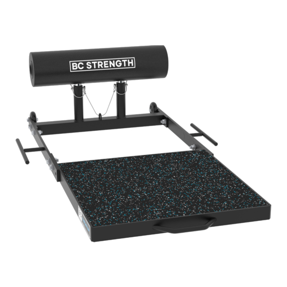
Thruster 3.0
ASSEMBLY
INSTRUCTIONS
Thank you for your recent purchase. Please read these instructions
carefully prior to assembling the Thruster 3.0.
This document includes assembly instructions for the Thruster 3.0,
as well accessories, including the Rotating Back Pad, please note this
accessory is optional.
Advertisement

Related Manuals for BC Strength Thruster 3.0


Summary of Contents for BC Strength Thruster 3.0
- Page 1 Thank you for your recent purchase. Please read these instructions carefully prior to assembling the Thruster 3.0. This document includes assembly instructions for the Thruster 3.0, as well accessories, including the Rotating Back Pad, please note this accessory is optional.
- Page 2 PARTS Tools Required (not included): 19 mm Crescent Wrench and 19 mm Socket Wrench BOLTS (x8) FOOT PLATE WASHERS (x16) BASE FRAME LOCK NUTS (x8) FOOT BASE (x1) SIDE SUPPORTS (x2) ROUND BACK PAD (x1) BACK FRAME (x1) ROTATING BACK PAD (optional) bcstrength.com | bcstrength.co.uk | bcstrength.com.au...
- Page 3 ASSEMBLY INSTRUCTIONS STEP 1 a) Place Foot Base (Part D) flat on the floor and *Height Guide attach Side Support (Part E). Make sure the We recommend that most users use the band pegs are facing outwards, and wheels shorter base position. However, individuals are towards the back of the unit.
- Page 4 ASSEMBLY INSTRUCTIONS STEP 3 a) Insert Round Back Pad (Part F), select and pin at desired height. Tighten all hardware. Your Thruster is now ready to use. STEP 4 (OPTIONAL) a) If using the Rotating Back Pad (Part H), insert, select and pin at desired height. STEP 5 (OPTIONAL) Disclaimer Warning: misuse of this equipment can result in severe...
Need help?
Do you have a question about the Thruster 3.0 and is the answer not in the manual?
Questions and answers