Subscribe to Our Youtube Channel
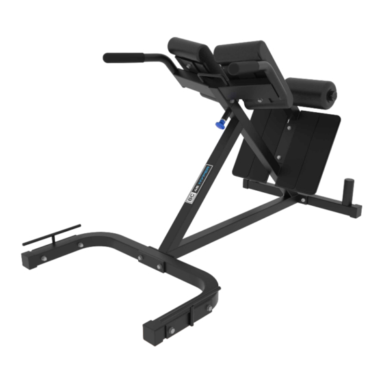
Summary of Contents for BC Strength 45-Degree Hyper
- Page 1 45-Degree Hyper ASSEMBLY INSTRUCTIONS Thank you for your recent purchase. Please read these instructions carefully prior to assembling the 45-Degree Hyper.
-
Page 2: Base Frame
PARTS Tools required (not included): 5 mm Allen Wrench, 17 mm Socket Wrench, 17 mm Crescent Wrench M10 x 75 BOLTS (x4) FOOT PLATE M10 x 70 BOLTS (x6) BASE FRAME M10 x 65 BOLT (x1) M10 x 25 BOLTS (x4) WASHERS (x26) LOCK NUTS (x11) BAND BRACKETS (x2) - Page 3 PARTS FRONT U BRACKET FRAME (x6) BASE FRAME (x1) FOOT PLATE BASE FRAME BACK FRAME (x1) FOOT PLATE (x1) NON SLIP STRIPS (x4) ROLLER PADS (x2) NON SLIP STRIPS () COLLETS (x2) ROUND TUBE (x1) bcstrength.com | bcstrength.co.uk | bcstrength.com.au...
- Page 4 PARTS TOP ASSEMBLY(x1) FOOT PLATE PLASTIC WASHERS (x4) bcstrength.com | bcstrength.co.uk | bcstrength.com.au...
- Page 5 ASSEMBLY INSTRUCTIONS STEP 1 a) Place Front U Bracket (Part I) and Base Frame (Part J) together and align holes. Insert b) Repeat on second hole and hand tighten M10 x 75 Bolt and Washer (Part A & E) then hardware.
- Page 6 ASSEMBLY INSTRUCTIONS STEP 4 b) Take the Foot Plate (Part L) and align holes on main assembly. (The larger U cutout a) *Attach Non Slip Strips (Part M) to Foot Plate should be facing downwards) Insert M10 x (Part L). Repeat for the other 3 pieces of Non 70 Bolt and Washer (Part B &...
- Page 7 ASSEMBLY INSTRUCTIONS STEP 6 a) Slide Plastic Washer (Part R) and then slide Roller Pad (Part N) on to round Tube (Part O). b) Slide subassembly from Step 6a on to base Lastly slide on another plastic washer (Part R). unit.
- Page 8 ASSEMBLY INSTRUCTIONS STEP 8 a) Take Pad (Part H) and align holes on main assembly of Part Q. Screw in M10 x 25 Bolt (Part D). Repeat on second hole. b) Repeat Step 8a on the other side. STEP 9 a) Fully tighten all bolts to complete the assembly.


Need help?
Do you have a question about the 45-Degree Hyper and is the answer not in the manual?
Questions and answers