Table of Contents
Advertisement
Quick Links
Document Type
Document No.
Document No.
Versio
ECR/PCNTCN
n
Issuing department
Archiving method
Formulate
d by
Date
Technical Documentation
i6-English Instructions
P Production Dept.
Audit by
Date
Process Code
Printing
Requirements
References
Description
Record of Revisions
Content Change
Purchasing Dept.
System
e-Documents
Colored
& White
Formul
ated by
Quality Dept.
□ Marketing Dept.
Paper Documents □ Other:
Approved by
Date
210
□
Black
Approval
Date
R&D
Advertisement
Table of Contents

Related Manuals for Amoul i6


Summary of Contents for Amoul i6
- Page 1 Document Type Technical Documentation Process Code Printing Colored □ Black Document No. Requirements & White i6-English Instructions References Document No. Description Record of Revisions Versio Formul Approval ECR/PCNTCN Content Change ated by Date P Production Dept. Purchasing Dept.
- Page 2 www.amoulmed.com...
-
Page 3: Table Of Contents
Table of Contents Table of Contents...........................I 1 Safety Instructions........................1 1.1 Safety Signs........................1 1.2 Safety Overview......................1 1.2.1 Hazards....................... 1 1.2.2 Warnings......................2 1.2.3 Considerations....................3 1.3 Contraindications......................3 2 Product Introduction........................5 2.1 Scope of application...................... 5 2.2 User Qualification......................5 2.3 Symbols Used on the Equipment..................5 2.4 ProductStructure and Function..................7 2.4.1 Product Structure....................7 2.4.2 Product Functions.................... - Page 4 4.3.3 Shock Recommended..................26 4.3.4 Shock Not Recommended................26 4.4 CPR Operation......................27 5 Manual Defibrillation.........................28 5.1 Overview........................28 5.2 Manual Defibrillation Screen..................28 5.3 Manual Defibrillation Settings..................29 5.4 Manual Defibrillation Steps..................30 5.1.1 External Defibrillation..................30 5.1.2 Internal Defibrillation..................32 5.5 Manual Synchronous Defibrillation................
- Page 5 10.2 NIBP Measurement Steps..................52 10.2.1 Measurement Preparation................52 10.2.2 Measurement Method...................52 10.2.3 Correct Measurement Results............... 53 10.3 Limitations of the Measurement................53 10.4 Measurement Mode....................53 10.5 Set initial Pressure.....................54 11 TEMP monitoring........................55 11.1 Overview........................55 11.2 TEMP monitoring display..................55 11.3 TEMP measurement steps..................
- Page 6 19.2.3 Limit Settings....................74 19.2.4 Alarm Parameter Settings................76 19.2.5 Clear Technical Alarms................... 76 19.2.6 Technical Alarm List..................76 20 Accessories..........................79 21 Technical Parameters....................... 80 21.1 Medical Device Management Class................80 21.2 Main Unit Specifications................... 80 21.3 Defibrillation Specifications..................81 21.4 AED Algorithm Performance..................84 21.5 Noninvasive Pacing Specifications................
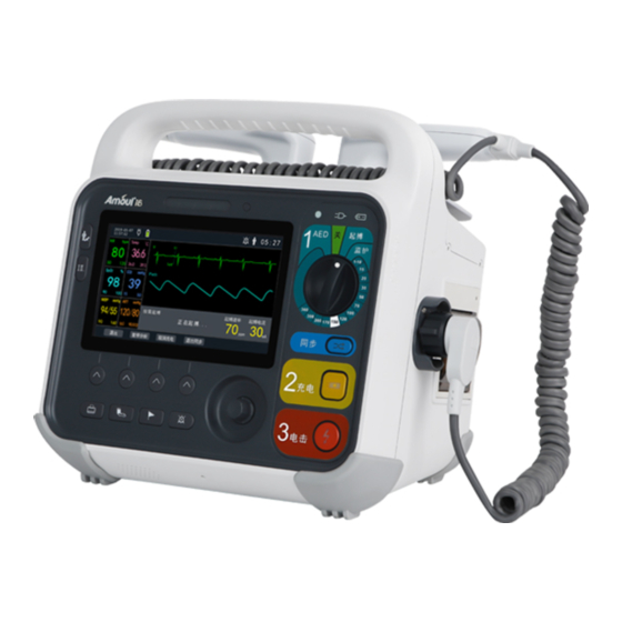
- Page 7 Product Information Thank you for purchasing the i6 defibrillator monitor. Please read and understand the contents of this instruction manual carefully before use, to operate the device correctly. Keep this manual in a safe place so that it can be easily referred to during the use of this product.
- Page 8 Intellectual property @2022 Ambul (Shenzhen). Tech Co., Ltd., all rights reserved. The intellectual property rights of this product and its instruction manual belong to Ambulanc (Shenzhen) Tech Co., Ltd., including but not limited to patents, trademarks, copyrights, etc. Ambulanc (Shenzhen) Tech Co., Ltd. reserves the right of final interpretation of this instruction manual.
- Page 9 Statement Ambulanc (Shenzhen) Tech Co., Ltd. reserves the right to modify the contents of the Manual without prior notice. Ambulanc (Shenzhen) Tech Co., Ltd. reserves the right to change the technology without prior notice. Ambulanc (Shenzhen) Tech Co., Ltd. reserves the right to modify product specifications without prior notice.
- Page 10 Maintenance service Scope of free service: • The free service is available for all devices that meet the warranty service regulations of Ambulanc (Shenzhen) Tech Co., Ltd. Scope of fee-based services: • Ambulanc (Shenzhen) Tech Co., Ltd. will implement fee-based services for any device that exceeds the scope of warranty service regulations of Ambulanc (Shenzhen) Tech Co., Ltd.;...
- Page 11 Toll-free service hotline: 400-9969-120 Tel: +86-755-26072215 Fax: +86-755-23016012 Website: http://www.ambulgroup.com E-mail: manager@ambu-lanc.com Product returns Returning procedure For necessary product returns to Ambulanc (Shenzhen) Tech Co., Ltd., please follow the steps below: • Approval for product returns: please contact the After-sales Service Department of Ambulanc (Shenzhen) Tech Co., Ltd.
- Page 12 by Ambul (Shenzhen) Tech Co., Ltd. This system is designed to provide physicians with the aids they need for clinical care. The physician is responsible for the treatment process. Ambulanc (Shenzhen) Tech Co., Ltd. shall not bear any responsibilities for the treatment process. Be sure to back up important data such as clinical records and notebooks to the external storage medium.
-
Page 13: Safety Instructions
Provide warning for conditions that can cause damage to the device and possibly improper treatment results. Prompts: provides helpful advice. The i6 Defibrillator Monitor is hereinafter referred to as "i6". 1.2 Safety Overview Function check must be performed before using this device (see "Inspection and Maintenance (19)"). -
Page 14: Warnings
• During defibrillation, keep a sufficient distance from the patient and metal objects connected to the patient to avoid electric shocks. 1.2.2 Warnings • The equipment, connection lines and accessories must be checked for proper operation before use. Do not use this device in case of failure is discovered. •... -
Page 15: Considerations
• When treating patients with implantable pacemakers, pads or paddles should be placed as far away from implantable pacemaker as possible. • Please place the power cord and cables of various accessories carefully to avoid entanglement or suffocation of the patient, or the cables from being tangled and electrically disturbed •... - Page 16 Patients who are responsive, breathing and have a pulse. • Manual defibrillation and asynchronous defibrillation: A conscious patient with a pulse. Patients with no pulse and no shockable rhythm (cardiac arrest or pulseless electrical activity). • Synchronous defibrillation: Patients with pulseless and unresponsive ventricular fibrillation, pulseless ventricular tachycardia or polymorphic tachycardia, pulseless activity, and cardiac arrest.
-
Page 17: Product Introduction
• Trained in CPR or other physician-authorized emergency response plans. • The Defibrillator Monitor i6 can be used in a medical institution or public places and supports pre-hospital or in-hospital use. • When used as a semi-automated external defibrillator in AED mode, the i6 is intended for use by medical personnel trained in basic life support (including the use of AEDs). - Page 18 Symbol Description Symbol Description sternum paddle icon Apex paddle icon Refer attached Do not discard in trash Handbook/Instructions "Shock" button Select Adult or Child Level of protection against Keep away from high heat ingress of solid particles and open flame, and do not Level of protection against dispose of battery in fire ingress of liquid...
-
Page 19: Productstructure And Function
Annex I of the Directive, therefore bears the CE marking 2.4 ProductStructure and Function 2.4.1 Product Structure The Defibrillator Monitor i6 consists of the main unit, battery, and pads (disposable pads for both adult and pediatric patients). 2.4.2 Product Functions There are four operating modes of the i6 defibrillator monitor: manual defibrillation, AED, pacer and monitoring. - Page 20 Parts Description When an alarm sounds, red and yellow flashes are displayed to Alarm indicate different alarm priorities. Red flashing = high, yellow flashing Indicator = medium, steady yellow = low. To bring up the main menu; display waveform changes; observe the Display Screen monitoring parameters;...
- Page 21 2- 2 Rear view Parts Description ①Equipotential Column Earthing ②Battery Pack Removable battery ③DC charging port For DC charging ④Network port For connecting the network (temporarily unavailable) ⑤USB For upgrade and data copy ⑥VGA Video interface (temporarily unavailable) ⑦Wire clip Secure the wires to prevent them from falling off.
- Page 22 2- 3 Left view Parts Description module interface Temp probe interface 1 Temp probe interface 2 NIBP NIBP cuff interface probe interface ECG lead wire interface • Main Unit- Right View...
- Page 23 2- 4 Right view Number Parts Description Plug Handle plug Printer Printer's paper tray • External Defibrillation Paddles The left image shows the sternum paddles, and the right image shows the apex paddles. 2- 5 Defibrillation paddles Number Parts Description...
- Page 24 Number Parts Description Electrode button For delivering shocks Indicator Effect indicator for skin contact with patients Energy increase increase or decrease shock energy /decrease button Electrode button For delivering shocks Charge button Charging for delivering shocks...
-
Page 25: System Operation
3 System Operation 3.1 Installation and Use The packing box of i6 contains the following items: i6 defibrillator monitor, user manual, battery, disposable defibrillator pad, ECG lead wire, SpO probe, cuff, and temperature probe for adults. Warnings: • The Defibrillator Monitor must be installed by the personnel designated by our Company. -
Page 26: Environmental Requirement
• Using Batteries The i6 can be powered by a rechargeable lithium battery. With the battery installed, if the external power supply goes off suddenly, the Defibrillator Monitor can automatically switch to the battery power. For the use of batteries, please refer to "16 Batteries". -
Page 27: Start Using The Device
Before switching on, check the defibrillator monitor for mechanical damage, and whether the pads, external cables, and accessories are properly connected. Plug the power cord into an AC power outlet. If using battery power, ensure that the battery has sufficient power; if using DC power, the inverter provided by our company must be used. -
Page 28: Screen Description
3.2 Screen Description 3.2.1 Main Screen 3- 1 Main screen Number Parts Description Heart Rate (HR) Heart rate detection Temperature (Temp) Current patient temperature Pulse Rate (PR) Displays patients’ arterial pulse rate Oxygen Saturation (SpO Indicates the ability of blood to carry oxygen Carbon Dioxide Current CO2 concentration in the blood... -
Page 29: Main Menu
Number Parts Description ECG Waveform Patient's ECG waveform Treatment time after Time elapsed since the start of the treatment start-up Patient Category Current patient category Technical Alarm Bar Displays technical alarm information Physiological Alarm Bar Displays physiological alarm information WIFI Network connection method (Optional) Alarm Silencing Sign Shows that the device is in silent mode... -
Page 30: System Settings
Exit button 3.3 System Settings Press the knob to enter the [Menu] settings, select the [System settings] tab, and press the knob to enter the settings screen, as shown below. On the screen, six modules such as [Alarm] [Volume] [Time] [Style] [Language] [Brightness] can be set. 3- 3 System settings screen 3.3.1 Alarm Settings Rotate the knob to select the [Alarm] tab, press, and enter the password to enter the... -
Page 31: Brightness Adjustment
3- 4 Alarm 3.3.2 Brightness Adjustment Rotate the knob to select the [Brightness] tab and press to enter the settings screen, as shown below. 3- 5 System settings - Brightness Set [Brightness]: can be set to levels 1-5, with 5 as the brightest level. Once set up, exit the settings screen, and the Defibrillator Monitor will automatically update to the latest settings. -
Page 32: Language Settings
3- 6 Volume Set [Voice prompt switch]: can be set to "On" or "Off". Set [Voice Prompt Volume]: can be set to levels 1-10. Set [Heartbeat Tone switch]: can be set to "On" or "Off". Set [Heartbeat Tone Volume]: can be set to levels 1-10. Once set up, exit the settings screen, and the Defibrillator Monitor will automatically update to the latest settings. -
Page 33: Time And Date Settings
3- 7 Language Set [Language]: select "Chinese" or "English". Once set up, exit the settings screen, and the Defibrillator Monitor will prompt that the device has changed its language and will restart. 3.3.5 Time and Date Settings Rotate the knob to select the [Time] tab, and press to enter the settings screen, as shown below. -
Page 34: Monitoring Parameter Settings
3- 9 Waveform settings Set [Waveform 1], [Waveform 2], and [Waveform 3]: "Waveform Selection," "Waveform Speed" and "Gain" can be set respectively. Once set up, exit the settings screen, and the Defibrillator Monitor will automatically update to the latest settings. 3.5 Monitoring Parameter Settings Press the knob to enter the [Menu] settings screen. -
Page 35: Aed
Set [Monitor Parameter 1] to [Monitor Parameter 6]: parameter categories corresponding to "Monitor Parameter 1" to "Monitor Parameter 6" can be selected respectively. Once set up, exit the settings screen, and the Defibrillator Monitor will automatically update to the latest settings. 4 AED 4.1 Overview This chapter describes how to operate AED and related prompts. -
Page 36: Aed Steps
In AED mode, the system displays only one ECG waveform from the multi-function pad. The AED information area in the middle of the screen displays information such as AED defibrillation, AED prompts, contact impedance indication (configurable), and the number of shocks. 4.3 AED Steps 4.3.1 AED Settings The AED-related information can be set as follows:... -
Page 37: Defibrillation Operation
4.3.2 Defibrillation Operation Confirm that the patient has suffered a cardiac arrest, and is in a non-breathing, non-pulsatile, non-responsive condition: Undo the patient's clothing, cut, or remove excessive chest hair and wipe the chest clean if necessary. Use the anterior-anterior pad placement position to attach the multi-function pad to the patient as indicated on the pad package. -
Page 38: Shock Recommended
prompt"High impedance, no shock delivered" appears, check if the patient's skin is clean and dry. If the message persists, replace the pad or electrode cable. 4.3.3 Shock Recommended In AED mode, the Defibrillator Monitor continuously performs rhythm analysis. When a shockable rhythm is detected, the Defibrillator Monitor will be automatically charged to a preset energy value. -
Page 39: Cpr Operation
automatically restart analysis when a potentially shockable rhythm is detected. Before the shockable rhythm is detected, the system will repeat the voice prompt of "A Shock is Not Recommended, press Pause for CPR If Needed," and cycles through the text prompt of "Shock is Not Recommended"... -
Page 40: Manual Defibrillation
• Do not place the paddles on your body to verify that their connection is valid. 5.2 Manual Defibrillation Screen The following figure shows the standard screen of i6 in a normal manual defibrillation state. 5- 1 Manual defibrillation energy... -
Page 41: Manual Defibrillation Settings
In manual defibrillation mode, the Defibrillator Monitor displays only one ECG waveform and related parameters. The defibrillation information area in the middle of the screen displays various related defibrillation information, such as defibrillation mode, synchronization identifier, defibrillation energy, patient contact impedance indication, defibrillation prompt, and several shocks. -
Page 42: Manual Defibrillation Steps
Select [Treatment Entry Mode] and select "Direct," "Password" and "Confirm". • If [Direct] is set, when manual defibrillation mode is selected, the manual defibrillation mode is directly entered. • If set to [Password], when manual defibrillation mode is selected, the Defibrillator Monitor will pop up in the password input menu. - Page 43 Do not touch this surface and the parts below it 5- 4 multi-functional paddles Warnings: During defibrillation, avoid touching places other than the insulated parts such as the paddle handle to prevent electric shock. Start the Defibrillator Monitor and enter the manual defibrillation mode. Select energy value: use the knob switch of the Defibrillator Monitor to set the required energy value.
-
Page 44: Internal Defibrillation
5.1.2 Internal Defibrillation If you need to use an internal defibrillation shock pad, please follow these steps: Open the i6 Defibrillator Monitor and select the manual defibrillation mode. Select the appropriate paddles according to the patient's condition. Insert the paddle cable into the therapy port of the Defibrillator Monitor and firmly insert it until it is in place. -
Page 45: Manual Synchronous Defibrillation
patient. Caution: • When the internal defibrillation paddles are used, the maximum energy value that can be selected is automatically limited to 50J to prevent from damaging the heart. • Always sterilize before using the internal defibrillation paddles, otherwise, it can cause serious infections. -
Page 46: Deliver An Additional Synchronous Shock
appear or is in the wrong position (for example, on the T wave), select another lead. Confirm that the Defibrillator Monitor enters the synchronized cardioversion mode. At this time, the "Sync" sign will appear in the defibrillation information area, and the "Sync" will disappear when existing synchronous defibrillation. -
Page 47: Monitoring Screen
The i6 supports the monitoring of ECG signals with 3- and 5-lead ECG lads, external defibrillation paddles, and multi-function pads. When the ECG lead is connected to the external defibrillation paddles or multi-function pads, the Defibrillator Monitor will display the ECG waveform from one of them according to the system settings. -
Page 48: Ecg Monitoring Settings
6- 1 ECG monitoring screen 6.3 ECG Monitoring Settings ECG-related information can be set as follows: Press the knob to bring up the Menu screen and select [General Configuration] - [ECG settings]. The ECG settings screen is shown in the following figure. 6- 2 ECG settings Select [Lead Type], which can be set to "3-Lead"... -
Page 49: Ecg Monitoring Steps
update to the latest settings. The default settings are 5-lead, 25.0 mm/s, Arrhythmia Analysis Off, Monitoring Mode, Power Frequency On, and Pacing Analysis Off. 6.4 ECG Monitoring Steps 6.4.1 Lead Monitoring Operation Skin preparation. To obtain a good ECG signal, the patient's skin must be cleaned before placing the ECG lead electrode or paddles, preferably in a flat area with less muscle. -
Page 50: Monitoring Operation With Paddles/Pads
LL: placed in the left lower quadrant. • 5-lead Take the AHA standard as an example, the electrode of the 5-lead is placed as shown in the figure: 6- 4 5-lead electrode placement position RA electrode: placed under the right clavicle, near the right shoulder. LA electrode: placed under the left clavicle, near the left shoulder. -
Page 51: Placement Of Paddles/Pads
• Use the paddles: remove the paddles set from the paddle slot by holding the handle with your hands and pulling the paddles straight upwards out of the paddle slot. After applying conductive paste to the paddles, place them on the patient using the anterior-anterior placement position. - Page 52 • For patients without a pacemaker, set [Pacing Analysis] to [No]. Otherwise, the system cannot detect arrhythmias associated with ventricular premature beats (including PVCs counts). Some pacemakers may cause false low heart rate or asystole alarms because pacemaker artifacts, such as pacemaker overshoot, may override true QRS waves.
-
Page 53: Non-Invasive Pacing
ECG waveform. In pacing mode, monitoring, and alarms for physiological parameters other than Resp can be performed as usual. The i6 supports both fixed and on-demand pacer modes: • Fixed pacer mode: the Defibrillator Monitor delivers pace pulses according to the set pacing rate. -
Page 54: Pacing Screen
Warnings: • During pacing, the heart rate and alarm provided by the Defibrillator Monitor may be inaccurate, and the patient should be observed closely. Do not rely on displayed heart rate or heart rate alarms as a measure of the patient's perfusion status. 7.2 Pacing Screen The standard screen of the Defibrillator Monitor in normal pacing status is shown in the figure below. -
Page 55: Pacing Steps
7- 2 pacing setting Select [Pacing Rate] to set the required rate or set the pacer mode on the parameter hotkey on the Defibrillator Monitor panel. Select [Default Pacing Method] to set "Fixed" or "On-demand" pacing. The pacer mode can also be set on the Defibrillator Monitor panel by using the hotkey. Select [Pacing Current] to set the required current or set the pacer mode using the parameter hotkey on the Defibrillator Monitor panel. - Page 56 Press the [Start] soft key to perform pacing, and a prompt"Pacing..." will appear in the pacing information area of the defibrillator monitor. Verify that the white pace mark appears on the ECG waveform. As shown in the figure below: 7- 3 Pacing Waveform Mark Pacing current adjustment: increase the pacing current until a capture occurs (capture is marked by a QRS complex following each pacing marker), and then lower the pacing current to the lowest level to maintain the capture.
-
Page 57: Co Monitoring
CO concentration in the gas sample. The mainstream CO module can be configured on the i6 defibrillator monitor. The operating temperature of the mainstream CO module is 0-55℃. measurement provides:... -
Page 58: Mainstream Co Module
4.CO upper alarm limit 5.Unit 8.3 Mainstream CO Module Caution: • The mainstream CO module is only applicable to patients undergoing mechanical ventilation (tracheal intubation). • Zeroing is required for the first use, and the zeroing time is about 15~20s. •... -
Page 59: Atmosphere Pressure Compensation
8.5 Atmosphere Pressure Compensation The CO module comes with the automatic atmosphere pressure compensation function. The system automatically measures the atmospheric pressure of the environment where the Defibrillator Monitor is located. 8.6 Measuring Influencing Factors The following factors may affect the accuracy of the measurement: Leakage or internal leakage of the sampled gas. -
Page 60: Spo 2 Monitoring
9 SpO Monitoring 9.1 Overview Continuous, non-invasive pulse oximetry is used for SpO measurement. It measures the light flux that reaches the photodetector end of the sensor after a specific wavelength of light emitted from the sensor's light source is absorbed by the oxygenated hemoglobin in the patient's tissues, thus obtaining the information on blood oxygen saturation and pulse rate. -
Page 61: Monitoring Settings
sensor and SpO cable otherwise, there may be a risk of harm to the patient. • When the patient is prone to hypoxia, a blood sample should be analyzed using an oximeter to fully grasp the patient's condition. • When a patient tends to be hypoxic, an oximeter should be used to analyze the blood sample to get a complete picture of the patient's condition. -
Page 62: Monitoring Steps
Once set up, exit the settings screen, and the Defibrillator Monitor will automatically update to the latest settings. The SpO value displayed on the Defibrillator Monitor is the result of averaging the data collected over a period. The shorter the average time, the faster the Defibrillator Monitor responds and the lower the measurement accuracy when the patient's SpO value changes. -
Page 63: Nibp Monitoring
10 NIBP Monitoring 10.1 Overview The non-invasive blood pressure monitoring method includes the Kirschner sound method (manual) and oscillation method. The Defibrillator Monitor adopts the oscillation method to measure the non-invasive blood pressure (NIBP), which applies to adults, children, and neonates. NIBP monitoring values include systolic blood pressure (SBP), diastolic blood pressure (DBP) and mean arterial pressure (MAP). -
Page 64: Nibp Measurement Steps
• The NIBP reading is affected by the measurement position, the patient's position, motion, and physiological state. If in doubt about the accuracy of the measurement results, check the vital signs of the patient by other means, and then check whether the Defibrillator Monitor is functioning properly. -
Page 65: Correct Measurement Results
To stop the measurement within the set time, press Stop Measurement on the Defibrillator Monitor panel. • Manual measurement Open the main menu screen, select [Basic Configuration], and open the [NIBP settings] menu. Set [NIBP Measurement Interval] to "Manual". Use the buttons on the Defibrillator Monitor panel to start or stop the measurement. -
Page 66: Set Initial Pressure
• Manual: perform an NIBP measurement manually when required. • Auto: the Defibrillator Monitor automatically and repeatedly performs NIBP measurements according to the set time interval. 10.5 Set initial Pressure You can manually set the initial inflation pressure for the cuff. Select the NIBP parameter area, open the [NIBP settings] menu, select [Initial Inflation Pressure] and set the appropriate cuff pressure. -
Page 67: Temp Monitoring
11 TEMP monitoring 11.1 Overview The defibrillator monitor can be used to measure the patient's body surface and intracavity temperature. The Defibrillator Monitor supports two-channel temperature measurement. arnings The temperature probe cable should be checked for proper operation before starting temperature monitoring. -
Page 68: Temperature Unit Setting
measurement requirements. If a disposable probe is used, connect the probe to the extension cable. Insert the probe or extension cable into the temperature probe connector. Attach the probe properly to the patient. Ensure that the alarm settings are applicable to the patient. Rotate the mode selection switch to monitoring mode. -
Page 69: Resp Monitoring
12 RESP Monitoring 12.1 Overview The thoracic impedance method was used for respiration measurement. When a patient is breathing, the chest impedance changes between the two ECG electrodes. The Defibrillator Monitor displays a respiratory wave on the screen by measuring the change in impedance. The Defibrillator Monitor calculates the respiratory rate (RR) according to the waveform period. -
Page 70: Place Respiratory Electrodes
[RESP settings]. The RESP settings screen is shown in the following figure: 12- 2 RESP settings Select [RESP Waveform Speed] to set the waveform speed to "6.25," "12.5" and "25". Select [Apnea Alarm Time] to set the alarm time to "10," "15," "20," "25," "30," "35" and "40". - Page 71 12- 3-lead electrode placement • Cardiac Activity Superposition The effect of cardiac activity on respiratory waveforms is called cardiac activity superposition. This occurs when the respiratory electrode picks up impedance changes caused by rhythmic blood flow. Proper placement of breathing electrodes reduces this impact. It should be avoided that the hepatic region and the ventricles are on the line of the respiratory electrodes to avoid artifacts generated by cardiac or pulsatile blood flow, which is particularly important in neonates.
-
Page 72: Recording Settings
13 Recording Settings 13.1 Recorder i6 uses a thermal array recorder. Patient information, measurement data, review data, and up to 3 waveforms can be produced through the recorder. 13.2 Recording Type • Recordings can be categorized according to the way they were triggered: Manually initiate the real-time waveform recording output. -
Page 73: Recording Settings
• The corresponding event is triggered. During recording, you can select the button to manually stop the recording: The recorder will automatically stop recording on the following occasions: • Recording task completion. • Recorder is out of paper. • A technical malfunction occurred in the recorder. •... -
Page 74: Recording Paper Loading
Once set up, exit the settings screen, and the Defibrillator Monitor will automatically update to the latest settings. 13.5 Recording Paper Loading Open the recorder door by turning outward the handle on the upper right corner of the recorder. Load the recording paper into the paper tray with the paper head located outside the paper outlet. -
Page 75: Clean Recorder
13.7 Clean Recorder After long-term use, paper dust and contaminants can accumulate on the printing head, affecting the recording quality and the life of the printing head and roller shaft. Please follow the following steps to clean the recorder: Before cleaning, take measures to prevent damage to the recorder from static electricity, such as wearing a disposable anti-static bracelet. -
Page 76: Marking Events
14 Marking Events During treatments or monitoring, various events may affect the patient, causing changes in certain waveforms or parameters. To assist in analyzing these impacts, you can manually mark certain events. You can define events A, B, C, D, E, F, G, H, before marking. For example, define event D as an injection of a drug. -
Page 77: Trend Review
15 Trend Review Under the operating modes of monitoring, manual defibrillation, and pacing, select [Menu] - [Trend Review] or select the [Trend] soft key in the monitoring mode to enter the trend table menu, as shown below: 15- 1 Trend Review... -
Page 78: Battery Management
16 Battery Management 16.1 Overview The Defibrillator Monitor is equipped with a maintenance-free lithium-ion rechargeable smart battery to ensure that the Defibrillator Monitor can be used normally even if the external power supply is not available. When AC power or DC power is turned on using an inverter, the battery can be charged regardless of whether the unit is turned on or not. -
Page 79: Charging The Battery
Disconnect the external power supply and use the battery to power the Defibrillator Monitor until the Defibrillator Monitor is turned off. The length of time the battery is powered will reflect the performance of the battery. If the battery is powered for significantly less than the time claimed in the specifications, replace the battery or contact maintenance personnel. - Page 80 batteries, the appropriate regulations should be followed. Warnings: Do not disassemble the battery, put it into a fire or short circuit it. Burning and explosion or leakage of the battery may cause personal injury.
-
Page 81: Cleaning And Disinfection
17 Cleaning and Disinfection The accessories of the defibrillator can be cleaned with common non-corrosive disinfectants and detergents, and the following are suitable detergents: • 90 % opropyl (except adapter, patient cable and Wi-Fi Data COMM card) • Soapy water •... -
Page 82: Inspection And Maintenance
18 Inspection and Maintenance 18.1 Routine Inspection Weekly and after each use of the i6 defibrillator monitor, do the following: Ensure that the equipment is clean. Ensure there are pads or paddles in the carrying bag. Turn the switch on to power up the device to perform self-tests and ensure that it can pass the self-tests. - Page 83 Inspection/Maintenance Items Weekly After use 12 months 24 months Recorder test ○ ○ × ○ ECG cable test ○ ○ × ○ Charge/discharge ○ ○ function Manual Disarm of energy ○ ○ defibrillation test × ○ Synchronous ○ ○ defibrillation Pacing test ○...
-
Page 84: Alarms
19 Alarms Alarm function refers to the devices’ system or the patient's vital signs that appear abnormal changes, the device reminds the staff to be more alert with sound, light, and text. The alarms are designed to improve patient safety by drawing attention from healthcare staff to values exceeding the preset normal level. -
Page 85: Alarm Settings
Medium alarm: Yellow, with a blinking frequency of 0.4 Hz-0.8 Hz. Low alarm: Yellow, steady on and not blinking "beep-beep-beep--beep-beep-----beep-beep-beep--beep-beep" (high alarm); Sound "beep-beep-beep" (medium alarm); "beep" (low alarm); When an alarm occurs, the alarm text prompt is displayed in the Text corresponding alarm area 19.2 Alarm Settings... -
Page 86: Limit Settings
19- 2 Alarm settings As shown in the figure, the relevant vital parameter alarm can be set to "On" or "Off," and the relevant vital parameter alarm level can be set to "High," "Med" and "Low". The alarm priority is from high to low. Once set up, exit the settings screen, and the Defibrillator Monitor will automatically update to the latest settings. - Page 87 As shown in the figure, the upper and lower alarm limits can be set for relevant life parameters. When the parameter value is lower than the lower limit or higher than the upper limit, the system will give an alarm. Once set up, exit the settings screen, and the Defibrillator Monitor will automatically update to the latest settings.
-
Page 88: Alarm Parameter Settings
19.2.4 Alarm Parameter Settings Configuration Items Options/Range Default Alarm Sound Switch On, Off Alarm Volume Level 1-10 Level 8 Alarm Pause Time 2 minutes ECG Off Priority High, Medium, Low High, Medium, Low Off Level HR Alarm Switch On, Off HR Alarm Level Medium, High High... - Page 89 Column I indicates how the technical alarms are cleared: A indicates that they can be cleared completely, and B indicates that they cannot be cleared. Column L indicates the default alarm level: "H" is high, "M" is medium, "L" is low, and "*" indicates the level can be set by the user.
- Page 90 the gas circuit NIBP overpressure The gas circuit may be blocked. Check protection and measure again. NIBP pump leakage Check the cuff and the inflation tube NIBP measurement A malfunction occurs during the timeout measurement and the system cannot perform the analysis and calculation. Check the patient's condition, check connections, or replace the cuff and measure again...
-
Page 91: Accessories
20 Accessories List of accessories Numb Quantit Name Unit Remark Instructions Quick guide External paddles (Adult/Children) ECG lead wire (stud-nap, 3-lead, U.S. Standard) ECG lead wire (stud-nap, 5-lead, U.S. Standard) ECG lead wire (stud-nap, 3-lead, European standard) ECG lead wire (stud-nap, 5-lead, European standard) ECG pads sensor (Children, repeatability) -
Page 92: Technical Parameters
21 Technical Parameters The specifications of the Defibrillator Monitor shall meet the requirements of GB9706.8 -2009 21.1 Medical Device Management Class Medical Device Management Class Class Class III medical device Electrical Safety Classification Parameter Value Dustproof and waterproof rating IP54 BF application section: CO and external defibrillation... -
Page 93: Defibrillation Specifications
Battery Specifications (with a fully charged new battery, at an ambient temperature of 20°C) Type Rechargeable lithium-ion battery Battery capacity 3500mAh Battery voltage Nominal 14.8 V Operating Operating Test conditions mode hours Maximum energy, charging interval Defibrillatio ≥ 100 greater than 1min, the printer is times not turned on 50Ω... - Page 94 Defibrillation External defibrillation paddles, multi-function pads, and internal Electrode Category defibrillation paddles It supports charging, discharging and energy selection, and has a charging External Paddles completion indicator and impedance indicator. Synchronous Discharge Delay Less than 60 ms (From R wave peak) Time External Manual Internal Manual...
- Page 95 The energy output accuracy meets the requirements in the following table. Impedance Energy Accuracy 25 Ω 50 Ω 75 Ω 100 Ω 125 Ω 150 Ω 175 Ω ±2J ±2J ±2J ±2J ±2J ±2J ±2J ±2J ±2J ±2J ±15 % ±15 % ±15 % ±15 %...
-
Page 96: Aed Algorithm Performance
Impedance Energy Accuracy 25 Ω 50 Ω 75 Ω 100 Ω 125 Ω 150 Ω 175 Ω 360J ±15 % 21.4 AED Algorithm Performance Targe Actual 90 % 90 % One- Mini Experi One-si Shock Non-sho Actual Target sided mental Heart rate Decisi Performa... -
Page 97: Noninvasive Pacing Specifications
Targe Actual 90 % 90 % One- Mini Experi One-si Shock Non-sho Actual Target sided mental Heart rate Decisi Performa Performa Lowe Samp Sampl Lower Decision Confid Confi ence denc Limit Limit (PVC) Specificity Specificit Cardiac Arrest 100 % 92 % =100 % y >95 % True predictive value: 98.18 % , false positive rate: 0.44 %... - Page 98 Basic ECG Monitoring Specifications 2.5 mm/mV (×0.25), 5 mm/mV (×0.5), 10 mm/mV (×1), 20 mm/mV (×2), 40 mm/mV (×4) with errors less than ±5 % Sensitivity Add ±300mV DC polarization voltage, the sensitivity variation range will be ±5 % Scan Speed 50mm/s, 25mm/s, 12.5mm/s, 6.25mm/s, with errors less than ±10 % Treatment mode 1Hz-20Hz (...
- Page 99 Basic ECG Monitoring Specifications ECG Input 0.2mV-8mV (at standard sensitivity 10 mm/mV) Signal Range Post-defibrillat ECG lead: <5 s ion Baseline Defibrillation lead: <5 s Response Time Electrode Polarization ±500 mV Voltage Range (ECG lead) Input Impedance ≥5 MΩ (ECG lead) Lead off Measuring electrode: <0.1 μA Detection...
-
Page 100: Spo Monitoring Specifications
Comply with the requirements of YY 1079-2008 Part 4.1.2.1 d). The average heart rate has been calculated as follows: If the last three consecutive RR intervals are greater than 1200 ms, the 4 Average Heart closest RR intervals are averaged to calculate heart rates. Otherwise, take the Rate 12 closest RR intervals, subtract the maximum and minimum values, and take the average to calculate the heart rate. -
Page 101: Respiratory (Resp) Monitoring Specifications
For adults, children, and neonates. Probe Repeatability. Specifications Acting on fingers Pulse Rate (PR) Specifications Measurement 30 bpm- 240 bpm Range Measurement ±3 bpm Accuracy Measurement 1 bpm Resolution High limit alarm Low limit alarm Alarm error PR Alarm Range PR low limit+ 2 bpm) - 25 bpm-(PR high limit- ±... - Page 102 Range TEMP Measurement ± 0.1 ℃ (± 0.2 ℉) (main unit) Accuracy TEMP Measurement 0.1 ℃ Resolution Minimum Accurate Body surface: 100 s Measurement Time Body cavity:< 80 s High limit alarm Low limit alarm Alarm error TEMP Alarm Range (TEMP low limit+ 0.0 ℃-(TEMP High limit- ±...
-
Page 103: Non-Invasive Blood Pressure (Nibp)
21.6.5 Non-Invasive Blood Pressure (NIBP) Non-Invasive Blood Pressure (NIBP) Specifications NIBP Manual measurement, automatic interval measurement, and continuous Measurement measurement Mode Interval Time of Automated 1 min, 2 min, 3 min, 5 min, 10 min, 15 min, 20 min, 30 min, 1 h, 2 h, 3 h, 4 h, Measurement 8 h. -
Page 104: Carbon Dioxide (Co 2 ) Monitoring Specifications
mmHg)- 230 limit- 5 mmHg) mmHg Low limit+ 5 Diastolic 10 mmHg-(High mmHg)- 210 pressure limit- 5 mmHg) mmHg (Low limit+ 5 Systolic 40 mmHg-(High mmHg)- 200 pressure limit- 5 mmHg) mmHg Chil (Low limit+ 5 20 mmHg-(High mmHg)- 165 limit- 5 mmHg) mmHg Low limit+ 5... -
Page 105: Recording Specifications
Time Interval of Continuous Measurement Measurement Mode Mainstream Start-up Time < 10 s Response Time < 120 ms Calibration Automated continuous self-calibration Manual calibration is not required Pressure Compensation With automatic barometric pressure compensation Relative Humidity 10- 90 % (no condensation) Accuracy (based on an atmospheric pressure of ±... -
Page 106: Environmental Specifications
Paper 21.8 Environmental Specifications: Operating environment Operate Temperature 0 ℃-50 ℃ Operate Humidity Relative humidity is 10 % - 95 % , non-condensing Atmospheric Pressure 57.0 kPa- 106 .2 kPa; Storage and Transportation Environment Storage and Transportation Temperature - 30 ℃- 70 ℃ Storage and Transportation Humidity Relative humidity is 10 % - 95 % , non-condensing... -
Page 107: Emc
22 EMC This product meets the requirements of YY0505-2012 for emission and immunity. The basic performance of EMC is as follows: "During the EMC testing, the display screen displays normally, no false alarms have occurred, and the instrument operates without any fault". 22.1 Warnings The pins of connectors marked with ESD warning symbols should not be touched and no connection should be formed to these connectors unless ESD precautions are taken. - Page 108 equipment is low. RF emission Class B GB4824 Harmonic emission The Defibrillator Monitor is suitable for use in Class A GB17625.1 all facilities, both non-domestic and not directly connected to the public low voltage Voltage power grid for residential use. fluctuation/Flicker Pass emission...
- Page 109 Guidelines and Manufacturer's Declaration - Electromagnetic Immunity The Defibrillator Monitor is intended to be used in the following electromagnetic environments. The purchaser and user should ensure that it is used in such an electromagnetic environment: Electromagnetic Immunity Test IEC 60601 Test Level Coincidence Level Environment - Guidelines...
- Page 110 hospital quality Grid power shall be of a typical commercial hospital quality. If the user of the Defibrillator Monitor needs Power frequency continuous operation magnetic field 3 A/m, 50 Hz 3 A/m during power (50/60 Hz) interruption, GB/T17626.8 recommended that the Defibrillator Monitor be powered uninterruptible...
- Page 111 Guidelines and Manufacturer's Statement - Electromagnetic Immunity The Defibrillator Monitor is intended for use in the following specified electromagnetic environments, which the purchaser or user should ensure that it is used in such an environment: Coincidence Electromagnetic Environment - IEC 60601 Immunity Test Level Guidelines...
- Page 112 propagation is affected by absorption and reflection from buildings, objects, and the human body. The ISM (industrial, scientific, and medical radio) band between 150 kHz and 80 MHz refers to 6.765 MHz-6.795 MHz, 13.553 MHz-13.567 MHz, 26.957 MHz-27.283 MHz, and 40.66 MHz-40.70 MHz.
- Page 113 For the maximum rated output power of the transmitter not listed in the above table, the recommended separation distance d in meters(m) can be determined by the formula in the corresponding transmitter frequency column, where P is the maximum rated output power of the transmitter provided by the transmitter manufacturer in watts (W).
-
Page 114: Product Assurance
23 Product Assurance Within two years from the date of purchase, the product quality problems that occurred during the normal operation according to the product instructions can be repaired free of charge by Shenzhen Ambul Tech Co., Ltd. If the warranty period indicated on the product is less than two years, this guarantee will also end with the end of the warranty period indicated on the packaging or in the instructions for use. -
Page 115: Classification Description Of Toxic And Harmful Substances
24 Classification Description of Toxic and Harmful Substances Name and Content of Toxic and Harmful Substances or Elements Hexava Polybromi Polybro Cadmi lent nated Mercur Lead minated Part Name chromi diphenyl y (Hg) (Pb) biphenyl (Cd) ether (PBB) (Cr, .VI) (PBDE) Battery ×... -
Page 116: Storage And Transportation
25 Storage and Transportation The Defibrillator Monitor can be transported with a common transportation method after it is packed in a packing box. The product should be protected from moisture, sunlight, and impact during transportation. See the table below: Graphic Symbol Description Graphic Symbol Description... -
Page 117: Defibrillator Monitor Shift Check List
26 Defibrillator Monitor Shift Check List Check the Defibrillator Monitor according to the items in the following table after daily use. If the items are normal, please tick in the "Normal" column. If there is any abnormality, please indicate the condition in the"Abnormal Condition Description" column and wait until all items are normal before the next use. -
Page 118: List Of Terms
Charge to 200 J, press the "Discharge" button, and the system prompts that a shock is released normally. Remove the test load after the test is completed. Electrode Shock Power on the device, select"Manual Test **(Test Defibrillation", connect Use) paddles. Put the electrode into the slot, charge it to 10 J, and press the "Discharge"... - Page 119 Ambulanc (Shenzhen) Tech. Co., Ltd. Address: 3rd Floor, Building 5#C, Innovation Valley, SKYWORTH Industrial Zone, No. 1 Tangtou Road, Shiyan Street, Baoan District, Shenzhen Tell: +86-755 26072210 Fax: +86-755 23016012 Website: www.amoulmed.com Email: manager@amoulmed.com...
Need help?
Do you have a question about the i6 and is the answer not in the manual?
Questions and answers