Advertisement
Quick Links
INTRODUCTION
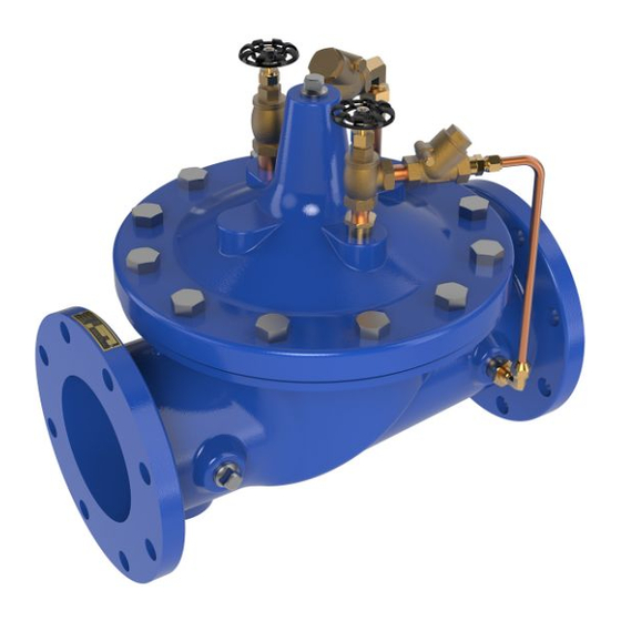
The Cla-Val Model 81-02/681-02 Check Valve is an automatic
valve designed to close drip tight when outlet pressure exceeds
inlet pressure. It is a hydraulically operated, pilot controlled,
diaphragm type globe or angle valve. When a pressure reversal
occurs, higher downstream pressure is applied to the cover cham-
ber through one control tube line and valve closes tightly. Upon
resumption of normal pressure, cover chamber pressure is relieved
through the other control tube line. The valve opens for flow. This
valve is equipped with adjustable opening and closing speed con-
trols.
INSTALLATION
1. Allow sufficient room around the valve to make adjustments, and
for disassembly.
2. It is recommended that gate or block valves be installed on both
ends of the 81-02/681-02 to facilitate isolating the valve for preven-
tive maintenance.
NOTE: BEFORE VALVE ASSEMBLY IS INSTALLED, PIPE
LINES SHOULD BE FLUSHED OF ALL CHIPS, SCALE AND
FOREIGN MATTER.
3. Place the valve in the line with flow through the valve in the
direction indicated on the inlet nameplate or by flow arrows. Check
all fittings and hardware for proper makeup and that no apparent
damage is evident. Be sure main valve cover nuts/bolts are tight.
4. Cla-Val valves operate with maximum efficiency when mounted
in horizontal piping with the cover UP; however, other positions are
acceptable. Due to size and weight of cover and internal compo-
nents of six inch and larger valves, installation with the cover up is
advisable. This makes periodic inspection of internal parts readily
accessible.
5.
Caution must be taken in the installation of this valve to insure that
galvanic and/or electrolytic action does not take place. The proper use
of dielectric fittings and gaskets are required in all systems using dis-
similar metals.
OPERATION AND START-UP
1. A Cla-Val X101 Valve Position Indicator may be installed in the
center cover port to provide a visual indication of the valve stem
during start-up.
2. Close the two speed control valves by turning full clockwise.
Open both valves 1/4 to 1/2 turn counterclockwise for an initial
setting.
3. With pressure in the piping, slowly open the gate or block valves
on both ends of the Cla-Val 81-02/681-02 Check Valve. Carefully
loosen the center cover plug of the Hytrol Valve, or the vent valve
of X101 Valve Position Indicator (if installed), and bleed air from
valve. Retighten cover plug or vent after all air is expelled.
4.To check the operation of the valve lower the pressure at the
valve inlet and the valve will close. Return the inlet pressure to a
81-02/681 02
INSTALLATION / OPERATION / MAINTENANCE
MODEL
higher pressure than the outlet pressure and the valve will open.
5. The opening and closing speed of the main valve is controlled
by the speed control valves. The opening control will be on the
smaller of the two control lines.
MAINTENANCE
1.Cla-Val Valves and Controls require no lubrication or packing
and a minimum of maintenance. However, a periodic inspection
schedule should be established to determine how the fluid handled
is affecting the operation of the valve assembly. Minimum of once
per year.
2. Repair and adjustment procedures of the Cla-Val Hytrol valve
and control components are included in a more detailed IOM
manual. It can be downloaded from our web site (www.cla-
val.com) or by contacting a Cla-Val Regional Sales Office.
3. When ordering parts always refer to the catalog number and
stock number on the valve nameplate.
SYMPTOM PROBABLE CAUSE
Fails to close
Fails to open
(Valve is
designed to
fail closed
on a
diaphragm
failure)
Check Valve
Lack of cover chamber
Check upstream and
pressure
downstream pressure,
tubing for restrictions
Diaphragm damaged
Replace diaphragm
Diaphragm assembly
Clean and polish stem
inoperative Corrosion
Replace any defective
or excessive scale build
part damaged, badly
up on valve stem
eroded
Mechanical obstruction
Remove obstruction
Object lodged in valve
Worn disc
Replace disc
Badly scored seat
Replace seat
Closing speed control closed
Open speed control1/4 turn
Insufficient line pressure
Check pressure
Diaphragm assembly
Clean and polish stem
in-operative Corrosion
Replace any defective part
on valve stem
damaged, badly eroded
Diaphragm damaged
Replace diaphragm
Opening speed control
Open 1/4 turn
closed
REMEDY
Advertisement

Subscribe to Our Youtube Channel
Related Manuals for CLA-VAL 81-02/681-02


Summary of Contents for CLA-VAL 81-02/681-02
- Page 1 2. It is recommended that gate or block valves be installed on both ends of the 81-02/681-02 to facilitate isolating the valve for preven- 5. The opening and closing speed of the main valve is controlled tive maintenance.
- Page 2 For a more detailed IOM Manual go to www.cla-val.com or contact a Cla-Val Regional Sales Office. CLA-VAL 1701 Placentia Ave • Costa Mesa CA 92627 Phone: 949-722-4800 • Fax: 949-548-5441 • E-mail: info@cla-val.com • www.cla-val.com N-81-02/681-02 (R-06/2018) Copyright Cla-Val 2018 Printed in USA Specifications subject to change without notice.
Need help?
Do you have a question about the 81-02/681-02 and is the answer not in the manual?
Questions and answers