
Related Manuals for Circutor RGU-10 MT Series


Summary of Contents for Circutor RGU-10 MT Series
- Page 1 Electronic earth leakage protection relay RGU-10 MT Serie INSTRUCTION MANUAL (M98228501-03-21A)
- Page 2 RGU-10 MT Instruction Manual...
-
Page 3: Safety Precautions
CIRCUTOR, SA reserves the right to make modifications to the device or the unit specifications set out in this instruction manual without prior notice. CIRCUTOR, SA on its web site, supplies its customers with the latest versions of the device specifica- tions and the most updated manuals. -
Page 4: Table Of Contents
RGU-10 MT CONTENTS SAFETY PRECAUTIONS ���������������������������������������������������������������������������������������������������������������������������������������������������������3 DISCLAIMER ��������������������������������������������������������������������������������������������������������������������������������������������������������������������������3 CONTENTS �����������������������������������������������������������������������������������������������������������������������������������������������������������������������������4 REVISION LOG �����������������������������������������������������������������������������������������������������������������������������������������������������������������������5 SYMBOLS �������������������������������������������������������������������������������������������������������������������������������������������������������������������������������5 1�- VERIFICATIONS UPON RECEPTION ����������������������������������������������������������������������������������������������������������������������������������6 2�- DESCRIPTION OF THE PRODUCT �������������������������������������������������������������������������������������������������������������������������������������6 3�- INSTALLING THE DEVICE �������������������������������������������������������������������������������������������������������������������������������������������������8 3�1�- PRELIMINARY RECOMMENDATIONS ������������������������������������������������������������������������������������������������������������������������8 3�2�- INSTALLATION ���������������������������������������������������������������������������������������������������������������������������������������������������������9 3�2�1�- INSTALLATION OF DEVICE IN PANEL ����������������������������������������������������������������������������������������������������������������9 3�3�- TERMINALS OF THE DEVICE ����������������������������������������������������������������������������������������������������������������������������������... -
Page 5: Revision Log
RGU-10 MT REVISION LOG Table 1: Revision log� Date Revision Description New version. 09/21 M98228501-03-21A Changes in the following sections: 3.4. SYMBOLS Table 2: Symbols� Symbol Description In compliance with the relevant European directive. In accordance with the CMiM directive. In accordance with the UKCA directive (UK Conformity Assessed) The device complies with the 2012/19/EC European directive. -
Page 6: 1�- Verifications Upon Reception
Perform an external visual inspection of the device before connecting it. d) Check that it has been supplied with the following: - An installation guide. Immediately contact the carrier and/or CIRCUTOR’s after-sales service if you de- tect any problem in the device upon reception. 2.- DESCRIPTION OF THE PRODUCT The RGU-10 MT is a type A earth leakage protection device. - Page 7 RGU-10 MT Main features: - Measuring in true effective value- - Type A differential (IEC 61008-1) - Insulation against transients (IEC 61008.1) - High frequency filtering (IEC 61008.1) - Trip setting between 80 and 100% I∆n - Inverse curve (IEC 61008.1) - Associated standard: IEC 61008.1, IEC755 - 3 modules.
-
Page 8: 3�- Installing The Device
RGU-10 MT 3.- INSTALLING THE DEVICE 3�1�- PRELIMINARY RECOMMENDATIONS The operators using and handling the device must follow the safety measures estab- lished in the country where the device will be used to guarantee its safe operation, using personal protective equipment if needed. The RGU-10 MT device must be installed by authorised and qualified staff. -
Page 9: 3�2�- Installation
RGU-10 MT 3�2�- INSTALLATION While the device is connected, the terminals, opening the cover or removing ele- ments can expose parts that are hazardous to the touch. The device must not be used until the installation process is complete. The device is installed on a DIN rail or on a panel (drilled panel 67 x 67 mm, according to DIN 43 700 using accessory). -
Page 10: 3�3�- Terminals Of The Device
RGU-10 MT Figure 2: Installation of adapter accessory� 3�3�- TERMINALS OF THE DEVICE Table 3:Terminal description RGU-10 MT� Terminal description 1: Trigger input - External reset 9: Interlock relay (NC) 2: Trigger input - External reset 10: A1, Power supply 3: Transformer current input 1S2 11: A2, Power supply / State of the circuit breaker 4: Transformer current input 1S1... -
Page 11: 3�4�- Connection Diagrams
RGU-10 MT 3�4�- CONNECTION DIAGRAMS 3�4�1�- CONNECTION WITH CURRENT SHUNT COIL L1 L2 L3 SUPPLY: 230 V ~ U> 10 11 13 14 15 Reset RGU-10 MT Test Disparo por BOBINA Trip by COIL. CARGA LOAD AJUSTE POR SETUP TRIP: St Bobina de emisión SEC.T: Pt Bobina de mínima... -
Page 12: 3�4�2�- Connection Without Coil With Mt-C-62/64 Circuit Breaker
RGU-10 MT 3�4�2�- CONNECTION WITHOUT COIL WITH MT-C-62/64 CIRCUIT BREAKER The device is connected to the power supply before the circuit breaker, which is the MT-C-62/64 mo- torized circuit breaker. SUPPLY: 230 V ~ L1 L2 L3 10 11 13 14 15 Reset RGU-10 MT Test... -
Page 13: 3�4�3�- Connection With Coil With Recmax Mp - C/D2/4
RGU-10 MT 3�4�3�- CONNECTION WITH COIL WITH RECmax MP - C/D2/4 The device is connected to the power supply before the circuit breaker, which is the RECmax MP-C/ D2/4 motorized circuit breaker. Alimentación Auxiliar: 230 V~ L1 L2 L3 Power Supply: 230 V~ U>... -
Page 14: 3�4�4�- Connection Without Coil With Recmax Mp -C/D2/4
RGU-10 MT 3�4�4�- CONNECTION WITHOUT COIL WITH RECmax MP -C/D2/4 The device is connected to the power supply before the circuit breaker, which is the RECmax MP-C/ D2/4 motorized circuit breaker. Alimentación Auxiliar: 230 V~ L1 L2 L3 Power Supply: 230 V~ 10 11 13 14 15 Reset... -
Page 15: 3�4�5�- Connection Without Coil With Mt-Tsd Circuit Breaker
RGU-10 MT 3�4�5�- CONNECTION WITHOUT COIL WITH MT-TSD CIRCUIT BREAKER The device is connected to the power supply before the circuit breaker, which is the MT-TSD motorized circuit breaker. Figure 9: RGU-10 MT: Connection without coil with the MT-TSD circuit breaker� Instruction Manual... -
Page 16: 4�- Operation
RGU-10 MT 4.- OPERATION 4�1�- GENERAL DESCRIPTION RGU-10 MT Small size 3 módule Instant current leakage Display Programming of parameters Backlit LCD display DIN rail Panel (Adapter accessory) Output Relays ASSOCIATED BREAKING DEVICE Earth leakage device with trip coil ASSOCIATED MEASURING DEVICE WG and WGS toroidal family... -
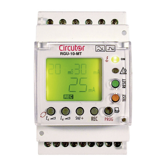
Page 17: 4�2�- Description Of The Device
RGU-10 MT 4�2�- DESCRIPTION OF THE DEVICE The front of the equipment which is formed by the display, buttons and LEDs, is protected with a seal- able plastic cover which has the appropriate holes to access the RESET, TEST and PROG/PAG keys. ON LED Interlock/reclosing LED RESET key... -
Page 18: 4�4�- Keyboard Functions
RGU-10 MT 4�4�- KEYBOARD FUNCTIONS The device has 7 keys, Figure 11 1�- Keys accessible with sealed cover and tool RESET, Starts the device after a trip. TEST, Carries out a trip to check the proper operation of the relay. ... -
Page 19: 4�5�- Display
RGU-10 MT 4�5�- DISPLAY The device has a backlit display with green or red light, depending on the state of the device. The background to the screen in normal mode is green. The parameters required for earth leakage protection, sensitivity and delay in its associated units are displayed. It also displays the current leak- age current. -
Page 20: 4�6�- Operation
RGU-10 MT 4�6�- OPERATION When the device is powered at its rated voltage, the green LED ON the front is on, the backlit LCD is green indicating the software and hardware version. After a short while, the version disappears and the default display values appear on the display. - Page 21 RGU-10 MT Table 9: Adjustment parameters� Parameter Units + (contact 8-7 NO) / nothing (contact 8 - 7 NC) Contact status: Interlock relay + (contact 8-9 NC) / nothing (contact 8 - 9 NO) Working frequency No. of peripheralss Communication baudrate Bauds Parity For the RGU-10C MT model only.
-
Page 22: 4�7�- Troubleshooting Or Reasons For Tripping
RGU-10 MT 4�7�- TROUBLESHOOTING OR REASONS FOR TRIPPING In the event of an earth leakage current trip due to a fault, test or error of the earth leakage trans- former. 1�- Look at the red display for the cause of the trip. 2�- The device starts a timer based on the sequence selected in the event of a trip. -
Page 23: 4�7�3�- Trip On Circuit Breaker Failure
RGU-10 MT 4�7�3�- TRIP ON CIRCUIT BREAKER FAILURE When the device trips due to a circuit breaker, the red LED is on continuously, the yellow LED flashes, and the LCD is backlit red. The display shows a “MAG” message, indicating the circuit breaker fault. Figure 18: Trip on circuit breaker failure�... -
Page 24: 5�- Configuration: Direct Settings
RGU-10 MT 5.- CONFIGURATION: DIRECT SETTINGS By pressing for a long time on any of the direct setting buttons, Configuration mode is entered and the relay’s setting may be changed. PROG will be shown on the display. While in Configuration mode if any other direct function is used (Id, td or Std/+), the parameter for the displayed relay can also be set. -
Page 25: 5�3�- Positive Safety Setting Of The Interlock Relay
RGU-10 MT 5�3�- POSITIVE SAFETY SETTING OF THE INTERLOCK RELAY “Std”, contacts are on standby: terminals 7 (NO), 8 (Common) and 9 (NC). “+”, contacts change status on powering the device, the + sign is displayed.. Terminals 7 (NC), 8 (Com- mon) and 9 (NO). -
Page 26: 6�- Configuration: Adjustments Using Setup Menu
RGU-10 MT 6.- CONFIGURATION: ADJUSTMENTS USING SETUP MENU To access the setup menu, long press the PROG key. PROG will be shown on the display. Figure 24: Setup menu� Instruction Manual... -
Page 27: 6�1�- Communications Settings
RGU-10 MT The device does not save changes to the settings until they are validated using the PROG key. When the keyboard is inactive for a certain period, the device exits the programming menu. “EXIT” is shown on the display and the changes are not saved. 6�1�- COMMUNICATIONS SETTINGS Note: The communications menu is only shown in the RGU-10C MT model. -
Page 28: 6�1�3�- Parity
RGU-10 MT When the desired value is shown on the screen, validate the number by pressing the PROG key. Programming values: 2�4 (2400 bauds), 4�8 (4800 bauds), 9�6 (9600 bauds), 19�2 (19200 bauds), 38�4 (38400 bauds), 54�6 (54600 bauds) and 115 (115000 bauds). 6�1�3�- PARITY To change the parity, press the td key repeatedly. -
Page 29: 6�2�3�- Circuit Breaker
RGU-10 MT To change the scales, press the td key repeatedly. Programming values: 10s - 30 A or 1s - 3 A� When the desired value is shown on the screen, validate the number by pressing the PROG key. The device exits the programming menu, and shows a screen with the “SAVE”... -
Page 30: 6�2�5�- Status Of The Contactors On The Coil
RGU-10 MT device exits the programming menu, and shows a screen with the “SAVE” message. 6�2�5�- STATUS OF THE CONTACTORS ON THE COIL The display shows SEC�T. To change the value, press the PROG key. To modify the status of the contactors on the coil, press the td key repeatedly. Programming values: St (standard) or PS (positive signal)�... -
Page 31: 7�- Configuration: Adjustments By Differential And Magnetothermic
RGU-10 MT 7.- CONFIGURATION: ADJUSTMENTS BY DIFFERENTIAL AND MAGNETOTHERMIC While the screens of differential and magnetothermic are displayed, floating screens, it is possible to view or modify: The number of partial and total reclosings. Assign the maximum number of reclosings. ... -
Page 32: 8�- Rs-485 Communications
RGU-10 MT 8.- RS-485 COMMUNICATIONS 8�1�- MODBUS CONNECTION The RS-485 connection must be wired using twisted pair cable with a mesh shield (minimum 3 wires), with a maximum distance of 1200 meters between the RGU-10C MT and the master unit. A maximum of 32 slave devices can be connected to this bus. -
Page 33: 8�2�2�- Write Example
RGU-10 MT 00 32: Address 0003: Working frequency (50 Hz) 00 00: Address 0004: Programmed trip current (0-30mA) 00 01: Address 0005: Time programmed for trip delay (1-INS) 00 00: Address 0006: Output polarity of trip relay (0-standard) 00 01: Address 0007: % IΔn pre-alarm trip. (1-50%) 00 14: Address 0008: Time programmed for pre-alarm delay. -
Page 34: 8�3�- Modbus Memory Map
RGU-10 MT 8�3�- MODBUS MEMORY MAP Table 10: Modbus memory map� Parameter Function Address Values Units Peripheral number 03/06 0000 1 ... 99 0: 2400, 1: 4800, 2: 9600, Communication baudrate 03/06 0001 3: 19200, 4: 38400, 5: 57600, 6: bauds 115200 Parity type... -
Page 35: 9�- Technical Features
RGU-10 MT 9.- TECHNICAL FEATURES Power supply AC Rated voltage 230 V ~ ± 20% , 110 V ~ ± 20% Frequency 50 - 60 Hz Consumption 6 VA Installation category CAT III 300 V Power supply DC Rated voltage 24 ... - Page 36 RGU-10 MT RS-485 Communications (RGU-10C MT Model) RS-485 Communications protocol Modbus RTU Baud rate 2400, 4800, 9600, 19200, 38400, 57600, 115200 Parity none - even - odd Environmental features Operating temperature -10ºC ... +50ºC Storage temperature -20ºC ... +55ºC Humidity (without condensation) 5 ...
-
Page 37: 10�- Technical Service
RGU-10 MT 10.- TECHNICAL SERVICE In the case of any query in relation to device operation or malfunction, please contact the CIRCUTOR, SA Technical Support Service. Technical Assistance Service Vial Sant Jordi, s/n, 08232 - Viladecavalls (Barcelona) Tel: 902 449 459 ( España) / +34 937 452 919 (outside of Spain) email: sat@circutor.com... -
Page 38: 12�- Ce Certificate
RGU-10 MT 12.- CE CERTIFICATE Instruction Manual... - Page 39 RGU-10 MT Instruction Manual...
- Page 40 RGU-10 MT Instruction Manual...
- Page 41 RGU-10 MT Instruction Manual...
- Page 42 CIRCUTOR, SA Vial Sant Jordi, s/n 08232 - Viladecavalls (Barcelona) Tel: (+34) 93 745 29 00 - Fax: (+34) 93 745 29 14 www.circutor.es central@circutor.com...
Need help?
Do you have a question about the RGU-10 MT Series and is the answer not in the manual?
Questions and answers