
Subscribe to Our Youtube Channel
Related Manuals for Electrolux Professional thermaline 1/1 GN


Summary of Contents for Electrolux Professional thermaline 1/1 GN
- Page 1 Multibraiser 1/1 GN – 2/1 GN Installation and operating manual * 599A0UP00 - 82.8060.01- 2021.07 *Original instructions...
- Page 2 Foreword Read the following instructions, including the warranty terms before installing and using the machine. Visit our website www.electroluxprofessional.com and open the Support section to: Register your product Get hints & tips of your product, service and repair information The installation, use and maintenance manual (hereinafter Manual) provides the user with information necessary for correct and safe use of the machine (or “appliance“).
-
Page 3: Table Of Contents
Contents A WARNING AND SAFETY INFORMATION....................5 General information ........................5 Personal protection equipment ......................6 General safety ..........................6 General safety rules ........................7 Safety signs to be placed near the machine area ................. 8 Transport, handling and storage ...................... 9 Installation and assembly ....................... - Page 4 OPERATING INSTRUCTIONS ....................... 26 Use ............................26 Features ........................... 27 Glass display ..........................27 Steel display..........................27 Main switch (optional) ........................27 First use ........................... 27 Using 2/1 appliance ........................27 I.7.1 Temperature control......................27 I.7.2 Roasting ......................... 27 I.7.3 Boiling and braising ......................
-
Page 5: Awarning And Safety Information
WARNING AND SAFETY INFORMATION General information To ensure safe use of the machine and a proper understanding of the manual it is necessary to be familiar with the terms and typographical conventions used in the documentation. The following symbols are used in the manual to indicate and identify the various types of hazards: WARNING Danger for the health and safety of operators. -
Page 6: Personal Protection Equipment
Personal protection equipment Summary table of the Personal Protection Equipment (PPE) to be used during the various stages of the machine's service life. Stage Protective Safety Gloves Glasses Safety garments footwear helmet ● ○ ○ — — Transport — ● ●... -
Page 7: General Safety Rules
• Do not use products (even if diluted) containing chlorine (sodium hypochlorite, hydrochloric or muriatic acid, etc.) to clean the appliance or the floor under it. • Do not use metal tools to clean steel parts (wire brushes or Scotch Brite type scouring pads). -
Page 8: Safety Signs To Be Placed Near The Machine Area
– well lit. For the Customer's complete information, the residual risks remaining on the machine are indicated below: such situations are deemed improper and therefore strictly forbidden. Residual risk Description of hazardous situation Slipping or falling The operator can slip due to water or dirt on the floor Burns/abrasions (e.g. -
Page 9: Transport, Handling And Storage
Danger Meaning caution, hot surface danger of electrocution (shown on electrical parts with indication of voltage) End of use • When the appliance is no longer to be used, make it unusable by removing the mains power supply wiring. Transport, handling and storage •... -
Page 10: Machine Space Limits
• Verify that a safety circuit breaker is installed between the power cable of the appliance and the mains electric line. The contact opening max. distance and leakage current must comply with the local safety regulations. • Be sure to power the equipment with systems that are protected against overvoltage; the manufacturer declines all responsibility for effects due to anomalies induced by the electrical supply system. -
Page 11: Additional Safety Information
Preventive maintenance • In order to ensure the safety and performance of your equipment, it is recommended that service is undertaken by Electrolux Professional authorised engineers every 12 months, in accordance with Electrolux Professional Service Manuals. Please contact your local Electrolux Professional Service Centre for further details. -
Page 12: Machine Disposal
(current/voltage/frequency, including spikes and/ subject to local terms and conditions. or outages); Check on Electrolux Professional website the list of authorized – inadequate or interrupted water supply, steam, air, gas customer care. (including impurities and/or other that does not comply with the technical requirements for each machine);... -
Page 13: Appliance And Manufacturer's Identification Data
See the data plate located in the lower right corner to identify the appliance (see fig. below). Electrolux Professional AG - Allmendstrasse 28, CH - 6210 Sursee MW freq IMPORTANT When installing the appliance, make sure the electrical connection is carried out in compliance with that specified on the data plate. -
Page 14: How To Interpret The Factory Description
Copyright port personnel. This manual is intended solely for consultation by the operator Manufacturer Electrolux Professional SpA or any other and can only be given to third parties with the permission of service centre authorised by Electrolux Electrolux Professional company. -
Page 15: Responsibility
Operator for an operator who has been informed and an integral part of the manual and therefore must be kept normal trained regarding the tasks and hazards together with it. machine use involved in normal machine use. Customer an operator instructed/trained by the Disposal of packing Care service Manufacturer and who, based on his... -
Page 16: Etransport, Handling And Storage
TRANSPORT, HANDLING AND STORAGE Introduction • make sure the load is stable; • make sure no material can fall during lifting. Manoeuvre Transport (i. e. transfer of the machine from one place to vertically in order to avoid impacts; another) and handling (i. e. transfer inside workplaces) must •... -
Page 17: Installation And Connection Diagram
4. Against the wall on concrete plinth 5. Back to back 1600 / 1700 / 1800 800 / 850 / 900 800 / 850 / 900 800 / 850 / 900 ≥ 70 ≥ 70 ≤ 100 ≤ 100 660 / 710 / 760 660 / 710 / 760 1460 / 1560 / 1660 NOTE! -
Page 18: Accessing The Appliance's Internal Components
drilling: ø18, depth 145mm 13 0 10 6 10 6 22 2 EI = Electrical connection EQ = Potential equalisation (x)* = Protective panel Accessing the appliance’s internal components... -
Page 19: Ginstallation And Assembly
Access to the main power connection INSTALLATION AND ASSEMBLY Appliance type • on steel plinth • on concrete plinth The appliances are suitable for setting up as single appliances or as a group of appliances. They can be positioned freely in the space provided, side by side, against a wall or back-to-back. -
Page 20: Positioning On Concrete Plinth
G.4.2 Positioning on concrete plinth 1. Transport the appliance on its transport pallet directly in front of the point of installation. 2. Remove the pre-cut plate at the bottom of the appliance. (for access, see F Installation DIAGRAMS). 3. Lift the unit on one side so that all installation connections are inside the appliance. -
Page 21: Securing Or Adjusting To The Floor (Optional)
G.4.4 Securing or adjusting to the floor (optional) If you need to secure it to the floor, the appliance comes with compatible adjustable feet. We recommend you adjust the feet so you end up with a working height of 900 mm. Level the unit with a spirit level. Attaching the unit with screws Attaching the unit by welding The feet have metal plates which may be secured to the floor... -
Page 22: Fastening Multiple Appliances Together
3. Remove the transport pallet. 4. Carry the appliance on the lifting cart to the prepared position on the wall and lift it to the correct height. 5. Remove the outer protective film and the edge covers, taking care not to scratch the surface of the appliance. Very slowly pull off the protective film on the stainless steel surfaces, without ripping, to prevent any adhesive residue. -
Page 23: Side Panels And Base Models
Using a solid tool, break nuts C from connecting rail D. Seal the whole length of the joint with long lasting Insert connecting rail D into the gap between the top, silicone (we recommend grey junction sealing, making sure marking E is pointing forwards. code: 059611). -
Page 24: Fixing The Side Panels
Fixing the side panels G.8.1 Panels with a 12,5 mm overhang Attach connecting rails B and C with the supplied Bring the side panel D into position. screws A. Make sure marking on part B on the rail is Put the 5 hooks of the panel F into the slots E. pointing forwards. -
Page 25: Side Cover Without Overhang
G.8.2 Side cover without overhang The side cover should only be used as a closing off against the wall, against a niche and in between appliances (provided that these have the same dimensions). Standard cover has pre-cuts that you can adapt to the appliances according to the left/right side. Fit the 4 cage nuts A into the dedicated slots on the Attach connecting rails C and D with the supplied frame. -
Page 26: Helectrical Installation
ELECTRICAL INSTALLATION Gas, electricity, water and other The Installation and Connection Diagram (F Installation DIAGRAMS) shows the position of the main terminal board. connections (if present, depending on To get access to the connection terminal inside the appliance, the appliance and/or model) follow the instructions in F.3 Accessing the appliance’s internal •... -
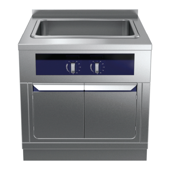
Page 27: Features
Features To properly perform basic cleaning, note and follow the instructions in J cleaning. Using 2/1 appliance 1. Splashback (optional) 2. Cooking pan 3. Drain plug I.7.1 Temperature control 4. Glass display only for 800 mm or 900 mm deep appliances 5. -
Page 28: Using 1/1 Appliances
Using 1/1 appliances Place the food in the pan. I.8.1 Temperature control • To switch on set temperature control to the temperature you want and turn heating control to the right level, depending on the quantity and type of food you are cooking. This appliance has the following heat settings: = no heat 1 - 3 = low heat (simmer / braise) -
Page 29: Stainless Steel Surfaces
CAUTION Collecting trays Do not use steel brushes, steel wool, • Empty and clean collecting trays, if present, on a daily basis. copper cloths, sand-based or similar prod- • Clean them with hot water. Add a degreasing detergent if ucts for cleaning necessary. -
Page 30: Heated Tanks/Containers
This list is just a short description; for detailed information, please read the service manual. Should none of the measures listed below resolve the fault or if an error occurs that is not described here, disconnect the appliance from the mains supply (gas, water, electricity) and immediately contact the Electrolux Professional Customer Care Service. -
Page 31: What To Do If
What to do if Problem Cause Solution Cannot use the appliance No power from local mains Switch on the main fuse E_13 • Overheating fault • Allow to cool • Display • Clean/unblock vents • Ventilator • Clean the filter •... - Page 34 Electrolux Professional AG Allmendstrasse 28 CH - 6210 Sursee www.electroluxprofessional.com...
Need help?
Do you have a question about the thermaline 1/1 GN and is the answer not in the manual?
Questions and answers