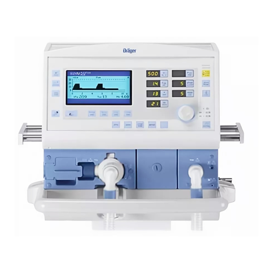
Dräger Medical Savina Manual
Intensive care ventilator
Hide thumbs
Also See for Savina:
- Operating instructions manual (160 pages) ,
- Operating instructions manual (144 pages)

Subscribe to Our Youtube Channel
Related Manuals for Dräger Medical Savina


Summary of Contents for Dräger Medical Savina
- Page 1 Technical Documentation Savina Intensive Care Ventilator Revision 8.0 5664.900 9036060 Because you care Emergency Care • Perioperative Care • Critical Care • Perinatal Care • Home Care...
-
Page 3: Table Of Contents
Contents General Notes Symbols and Definitions ......................4 Function Description General Working principle ........................7 Monitoring ..........................7 Principal components Electronics ..........................10 Control panel ........................14 Pneumatics ........................... 17... - Page 4 Replacing the dust filter set Replacing the O2 sensors Replacing the filter in the O2 inlet Replacing the lead-gel battery (internal battery) Schematics and Diagrams Front view, Savina Rear view, Savina Identification of PCBs O2 Valve PCB ........................46 Control PCB .......................... 48 Front Panel PCB ........................
- Page 5 Contents Pneumatic diagrams Tubing diagram Annex Parts catalog Test List Technical Information...
- Page 6 Contents...
- Page 7 General...
-
Page 9: Notes
Savina General Notes This Technical Documentation conforms to the IEC 60601-1 standard. Read each step in every procedure thoroughly before beginning any test. Always use the proper tools and specified test equipment. If you deviate from the instructions and/or recommendations in this Technical Documentation, the equipment may operate improperly or unsafely, or the equipment could be damaged. -
Page 10: Symbols And Definitions
General Savina Symbols and Definitions This symbol indicates a warning. This symbol indicates tips and useful information. This symbol is used to alert against unsafe practices when handling electrostatic sensitive devices (ESD). Definitions according to German standard DIN 31051: Inspection... -
Page 11: Function Description
Function Description... -
Page 13: General
Savina Function Description General Savina is a long-term ventilator unit designed for patients with a tidal volume of 50 mL and above, and for the following applications: – Intensive care unit – Recovery room, – Secondary transportation from hospital to hospital, –... - Page 14 Function Description Savina Measurement of the total frequency Determined over 1 minute and fil- (Ftot) tered. Measurement of the spontaneous Determined over 1 minute and fil- frequency (Fspn) tered. Measurement of the inspiratory-expi- Using the phase information from ratory ratio (I:E).
-
Page 15: Principal Components
A disconnection time, by which the “!!! Airway pressure low” warning is additionally delayed, is only adjustable in NIV. Principal compo- Savina consists of the electronics, the operator control unit and the pneu- nents matic system, containing the following principal components:... -
Page 16: Electronics
2.1.1 Power pack The power pack delivers the supply voltages for Savina. The input voltage range of the power pack is 100 V to 240 V AC and 50 Hz to 60 Hz. However, the power pack can also be operated with an external rechargeable battery (12 V or 24 V) or with an external on-board - ambulance/helicopter - power supply (10.5 V to 36 V). - Page 17 The internal rechargeable batteries supply the O2 sensors with power, even when the Savina is switched off. As a result, valid O2 values are available immediately on power-up.
- Page 18 Function Description Savina The control PCB contains the following functions: – Processing of the signals from the sensors (O2, flow, pressure, tempera- ture), – Control of the blower and valves – Monitoring of the unit functions and the supply voltages –...
- Page 19 Savina Function Description The Motor Commutation PCB delivers the “actual rotation speed signal” to the Control PCB. The “actual value signal” is 6 pulses per rotation. In the event of discrepancies in the rotation speed the Control PCB adjusts the speed according to the deviation.
-
Page 20: Control Panel
Function Description Savina 2.1.5 O2 Diaphragm PCB The O2 Diaphragm PCB amplifies the signals from the O2 sensors and mea- sures the temperature of the O2 sensors and of the respiratory gas in the inspiration block. The temperature of the O2 sensors is required to compen- sate for the temperature-sensitive O2 measurements. - Page 21 Savina Function Description Figure 7 Control panel block diagram 2.2.1 Front Panel PCB The Front Panel PCB contains the 7-segment displays for the pre-set ventila- tion parameters, the drivers for the key LEDs, the drivers for interpretation of the keys and the shaft encoder, and the voltage generator for backlighting of the display.
- Page 22 Savina 2.2.3 Membrane keypad The membrane keypad contains the keys, with associated LEDs, to operate the Savina. 2.2.4 Control knob The control knob is used to set and confirm changeable ventilation parame- ters. The control knob transmits square signals to the Front Panel PCB as it rotates, and the signals are then evaluated by the Control PCB.
-
Page 23: Pneumatics
Savina Function Description Pneumatics Figure 9 Pneumatic diagram 8412996, revision 23 5664.900... - Page 24 Function Description Savina Pos. no. Designation Micro-filter (AIR) Filter (O2) Filter for inspiratory flow sensor Filter (filter element) Suction sound muffler Sound absorber Oxygen pressure regulator Blower Blower and motor Cooler Cooler Injector Injector Reduction valve Expiratory valve Switching valve, oxygen compensation Switching valve, nebulizer V6.1...
- Page 25 Savina Function Description Pos. no. Designation Expiratory non-return valve Inspiratory non-return valve Flush-flow non-return valve Oxygen connection non-return valve (1) Flush flow restrictor (0.1 L/min at 30 mbar) O2 calibration restrictor (0.1 L/min, integrated in valve block) Restrictor for O2 measurement (0.2 L/min at 30 mbar, sen- sor 3.1)
- Page 26 Function Description Savina The expiratory valve has two functions: – Controls the PEEP during expiration – Closes the breathing system during inspiration 2.3.2 O2 mixture with O2 high In order to be able to ventilate with an increased O2 concentration, the unit pressure must be supplied with 2.7 to 6.0 bar O2.
- Page 27 Savina Function Description 2.3.6 O2 calibration function In normal operation of the unit the solenoid valve V4 is set to “measurement” - that is, the connection between the inspiration and the oxygen sensor is open. During O2 sensor balancing it opens the way for the oxygen to the sen- sor.
- Page 28 Function Description Savina 5664.900...
-
Page 29: Maintenance Procedures
Maintenance Procedures... -
Page 31: General Notes
Savina Maintenance procedures General notes Disinfect and clean the unit or parts of the unit prior to each mainte- nance procedure. For “replacement of wear and tear parts” intervals, refer to the Instructions for Use manual. The following replacement procedures are described in this doc- ument: –... - Page 32 4. Insert the new microfilter into its mount as far as it will go. 5. Dispose of the contaminated microfilter with the normal household waste. Always use the Savina with a microfilter installed, otherwise the inspiratory side will be contaminated! 6.
-
Page 33: Replacing The Dust Filter Set
Savina Maintenance procedures Replacing the dust 1. Press and hold the two tabs (Figure 4-1). filter set 2. Lift and remove the filter cover (Figure 4-2). Figure 4 Removing the filter cover 3. Pull the contaminated dust filters out of the filter cover (Figure 5-1). -
Page 34: Replacing The O2 Sensors
Maintenance procedures Savina Figure 6 Installing the filter cover Replacing the O2 1. Swivel the inspiratory port down (Figure 7-1). sensors 2. Unscrew the screw (Figure 7-2), e.g. using a coin, and remove the cover plate. 3. Remove the spent O2 sensor from its mount... -
Page 35: Replacing The Filter In The O2 Inlet
Savina Maintenance procedures Sensor 1 will be calibrated automatically after installation. Sensor 2 allow a maximum warm-up time of 20 minutes, then calibrate manually. Replacing the filter in the O2 inlet Hazardous voltage. Touching live components can lead to serious injury or death. - Page 36 Maintenance procedures Savina Figure 9 Rear panel fixing screws 7. Remove the rear panel. 8. Remove the microfilter (Figure 10). 9. Remove the plug-in unit (Figure 10). Figure 10 Removing the microfilter 10. Remove the valve block fixing screws (Figure 11).
- Page 37 Savina Maintenance procedures Figure 11 Valve block fixing screws Remove the sealing ring from the NIST connector. Otherwise the sealing ring could be lost during further disassembly. 11. Remove the NIST connector (Figure 12) (if fitted) and the sealing ring.
- Page 38 Maintenance procedures Savina Figure 13 Removing the inspiratory flow sensor 13. Remove large, transparent hose (which connects valve block to plug-in unit) from the plug-in unit. 14. Pull out the valve block a little and turn it 90° counter-clockwise (Figure 14).
- Page 39 Savina Maintenance procedures 18. Remove the valve block. 19. Remove the NIST connector mount screws (Figure 15). Figure 15 Removing the NIST connector mount 20. Remove the NIST connector mount. Before removing the filter and the seal, make a note of their fitting posi- tions.
-
Page 40: Replacing The Lead-Gel Battery (Internal Battery)
Maintenance procedures Savina Figure 16 Position of hoses 24. Check the unit according to the Test List and the Instructions for Use manual. Replacing the lead- gel battery (internal battery) Hazardous voltage. Touching live components can lead to serious injury or death. Disconnect power cord from AC outlet before opening device. - Page 41 Savina Maintenance procedures Figure 17 Removing the filter cover 6. Remove the screws from the rear panel (Figure 18). Figure 18 Rear panel fixing screws 7. Remove the rear panel. Remove the fuse for the rechargeable batteries by levering it out carefully with a screwdriver.
- Page 42 Maintenance procedures Savina Figure 19 Removing the fuse 9. Remove the cover fixing screws and remove the cover (Figure 20). Figure 20 Rechargeable batteries cover Rechargeable batteries represent special waste. Dispose of recharge- able batteries in conformity with local waste disposal regulations.
- Page 43 To charge the rechargeable batteries, leave the Sav- ina connected to the AC power supply for at least 10 hours (it is not necessary to switch on the Savina). 13. Check the unit according to the Test List and the Instructions for Use manual.
- Page 44 Maintenance procedures Savina 5664.900...
-
Page 45: Schematics And Diagrams
Schematics and Diagrams... -
Page 47: Front View, Savina
Savina Maintenance Procedures Front view, Savina Figure 1 Front view, Savina Table 1 Legend to Figure 1 Position no. Name Membrane keypad Control knob Inspiratory connection Expiratory valve Expiratory flow sensor 5664.900... - Page 48 Maintenance Procedures Savina Figure 2 Front view with front panel and Control PCB folded away Table 2 Legend to Figure 2 Position no. Name Power supply unit Motor Drive PCB with fuse Front Panel PCB Display Control PCB 5664.900...
-
Page 49: Rear View, Savina
Savina Maintenance Procedures Rear view, Savina Figure 3 Rear view, Savina Table 3 Legend to Figure 3 Position no. Name MEDIBUS interface Nurse call Power switch Fuse of the rechargeable batteries Mains connection Direct voltage socket Earthing stud Oxygen concentrator connector (“LPO” option) - Page 50 Maintenance Procedures Savina Figure 4 Rear view of the Savina with rear panel removed Table 4 Legend to Figure 4 Position no. Name Power supply unit Blower Cooler O2 sensor connector S3.2 with restrictor R6 Bypass valve V1 Rechargeable batteries...
- Page 51 Savina Maintenance Procedures Figure 5 Rear view with micro-filter and its housing removed Table 5 Legend to Figure 5 Position no. Name Inspiratory flow sensor S2 O2 Diaphragm PCB Valve block Nebulizer solenoid valve V5 Solenoid valve V4 to the O2 sensor S3.1...
-
Page 52: Identification Of Pcbs
Maintenance Procedures Savina Identification of PCBs O2 Valve PCB Figure 6 O2 Valve PCB, view 1 Table 6 Legend to Figure 6 Position no. Name To the Control PCB Oxygen pressure sensor Absolute pressure sensor To the nebulizer valve To the O2 calibration valve To the valve block 5664.900... - Page 53 Savina Maintenance Procedures Figure 7 O2 Valve PCB, view 2 Table 7 Legend to Figure 7 Position no. Name Absolute pressure sensor 5664.900...
-
Page 54: Control Pcb
Maintenance Procedures Savina Control PCB Figure 8 View, Control PCB 5664.900... -
Page 55: Front Panel Pcb
Savina Maintenance Procedures Front Panel PCB Figure 9 Front Panel PCB, view 1 Table 8 Legend to Figure 9 Position no. Name Display backlighting To the loudspeaker To the keys To the LEDs To the control knob To the Control PCB... -
Page 56: O2 Diaphragm Pcb
Maintenance Procedures Savina Figure 10 Front Panel PCB, view 2 O2 Diaphragm PCB Figure 11 O2 Diaphragm PCB, view 1 Table 9 Legend to Figure 11 Position no. Name To the Control PCB To the NTC in the inspiration block... - Page 57 Savina Maintenance Procedures Figure 12 O2 Diaphragm PCB, view 2 Table 10 Position no. Name To O2 Sensor 2 5664.900...
- Page 58 Maintenance Procedures Savina Pneumatic diagrams Figure 13 Pneumatic diagram, revision index 07 5664.900...
- Page 59 Savina Maintenance Procedures Figure 14 Pneumatic diagram 8412996, revision index 23 5664.900...
- Page 60 Maintenance Procedures Savina Tubing diagram Figure 15 Tubing diagram 5664.900...
- Page 61 Savina Maintenance Procedures Figure 16 Tubing diagram 8413759, revision index 06 5664.900...
- Page 62 Maintenance Procedures Savina 5664.900...
- Page 63 Annex Parts catalog Test List Technical Information...
- Page 65 Parts catalog Savina Revision: 2005-12-19 10:40:36 5664.900 Because you care Emergency Care - Perioperative Care - Critical Care - Perinatal Care - Home Care...
- Page 67 Parts catalog Products concerned Item Qty.u Part No. Description Qty. Remark 8414000 Savina basic unit 1.000 Items that are shown in the illustration but are not listed below the illustration are not available as spare parts 5664.900 Revision: 2005-12-19 10:40:36...
- Page 68 Parts catalog Trolley Item Qty.u Part No. Description Qty. Remark 8411970 SET CYLINDER BRACKET EV. MOBIL 1.000 2 pieces 8411973 Inlet 1.000 Items that are shown in the illustration but are not listed below the illustration are not available as spare parts 5664.900 Revision: 2005-12-19 10:40:36...
- Page 69 Parts catalog Temperature sensor AWT Item Qty.u Part No. Description Qty. Remark 8405371 TEMPERATURE SENSOR 1.000 Items that are shown in the illustration but are not listed below the illustration are not available as spare parts 5664.900 Revision: 2005-12-19 10:40:36...
- Page 70 Parts catalog Expiration Valve Item Qty.u Part No. Description Qty. Remark 8413660 EXPIRATION VALVE 1.000 Items that are shown in the illustration but are not listed below the illustration are not available as spare parts 5664.900 Revision: 2005-12-19 10:40:36...
- Page 71 Parts catalog Savina TransportMobil Item Qty.u Part No. Description Qty. Remark 8415810 Lockable castor 1.000 8414227 CASTOR 1.000 8414228 ROLLER, UNLOCKED 1.000 8415821 Handle interface kit 1.000 8415817 Telescopic rod 1.000 MP00050 Infusion bottle cross, 4-arm 1.000 8415815 Clamp bush with T-handle 1.000...
- Page 72 Parts catalog Savina TransportMobil Item Qty.u Part No. Description Qty. Remark 8415545 Coupling, device-side 1.000 8414217 TOMMY SCREW 1.000 1255673 Spherical end-piece 1.000 Items that are shown in the illustration but are not listed below the illustration are not available as spare parts 5664.900...
- Page 73 Parts catalog Savina TransportMobil Item Qty.u Part No. Description Qty. Remark 8415544 Coupling, bedside 1.000 Items that are shown in the illustration but are not listed below the illustration are not available as spare parts 5664.900 Revision: 2005-12-19 10:40:36...
- Page 74 Savina Parts catalog Assembly Description Part No. Accessories for operation O2-HOSE NIST 3M DIN PROBE M34402 O2-HOSE NIST 5M DIN PROBE M34403 Adult-Ventilation ADULT HOSE SET, F+P 8412108 Anfeuchter-Grundeinh. MR850AGU 8414720 AQUAPOR (220-240V) 8405020 Aquapor EL, Humidifier 8414698 F&P MR 730 AGU Befeuchter...
- Page 75 Savina Parts catalog Assembly Description Part No. ext. Battery/accessories BATTERY 12V/17AH 1843303 DC-battery cable S 8414092 DC-Board mains cable S 8414048 Infant Vent. w. MR 730/850 DRAW WIRE 1,50 M 900 MR 070 8411050 DUAL AIRWAY TEMP. SENSOR 1,45M 8411048 F&P MR 340 Kammer (d)
- Page 76 Savina Parts catalog Assembly Description Part No. Instructions for use Savina GA Savina Sw 2.n ru 9037392 IDU Savina SW 3.n fi 9037964 IFU Savina 2.1 fr 9037627 IFU Savina english 9037388 IFU SAVINA ES 9029173 IFU Savina french 9037389...
- Page 77 Savina Parts catalog Assembly Description Part No. UM Savina SW 2.n nl 9037427 UM Savina SW 3.n enUS 9037958 int. Battery/accessories ACCU 12V 3,5AH 1841416 DC-Connecting AKKU, AKKU 8413604 Maintenance parts/service Kits BATTERY 12V/17AH 1843303 Membrane, complete 8413661 MICROFILTER 6737545...
- Page 78 Power cable Great Britian 3m black 1844369 POWERCORD CH 3M 1844377 SUPPLY MAIN, 3M 1824481 Powerpack all SW-versions FUSE 15A 1850369 FUSE,5A 1850377 Products concerned Savina basic unit 8414000 Savina TransportMobil belt 8411972 CASTOR 8414227 Clamp bush with T-handle 8415815 Coupling, bedside 8415544 Coupling, device-side...
- Page 79 Test List Savina Serial no. File no.: 5664.900 Installation site Edition: 08.2005 5664.900 Savina Version 4.0 Test List...
- Page 80 Pressure gauge 0 mbar to 120 mbar Class 1.6 Flowmeter 10 L/min to 120 L/min Class 1.6 Flowmeter 0.01 L/min to 14 L/min Class 1.6 Syringe, 50 mL T-piece or Y-piece Thermometer Test pressure regulator Injector 5664.900 Savina Version 4.0 Test List...
- Page 81 General condition • Markings on Savina are complete and legible. • Savina is undamaged. • Dust filter must not be dirty or pressed together. • Micro-filter has been replaced at regular intervals. • Inspiration block is undamaged. • Check locking function of the expiratory valve mount.
- Page 82 The equivalent leakage current is less than/equal to 1000 A 6.1.3 Equivalent patient leakage current • Measure the equivalent patient leakage current according to VDE 0751. The equivalent patient leakage current is less than/equal to 5000 A 5664.900 Savina Version 4.0 Test List...
- Page 83 • Measure the patient leakage current according to IEC 60601-1. Normal condition (N.C.): I less than or equal to 100 A Single fault condition (S.F.C.): Neutral conductor interrupted: I less than or equal to 500 A 5664.900 Savina Version 4.0 Test List...
- Page 84 • Switch off the device. • Using the test pressure regulator and the injector set a flow of 60 L/min ±1 L/min. The emergency air valve opens. The pressure at the Y-piece is -3 mbar to -6 mbar. 5664.900 Savina Version 4.0 Test List...
- Page 85 Airway pressure limit: Paw high = 10 mbar above peak pressure • Seal the expiratory hose. The unit builds up a pressure up to the Paw high limit, then the pressure is reduced momentarily to less than 6 mbar through the emergency expiratory valve. 5664.900 Savina Version 4.0 Test List...
- Page 86 • Supply unit to customer ready for operation. Date: _ _ _ _ _ _ _ _ _ _ _ _ _ Name: _ _ _ _ _ _ _ _ _ _ _ _ _ _ _ _ 5664.900 Savina Version 4.0 Test List...
- Page 87 Savina should be observed to verify normal use in the configuration in which it will be used. Other equipment which can be used adjacent to or stacked with the Savina are listed in the Instructions for Use manual, in the Order List chapter or in the following table.
- Page 88 Electromagnetic Emissions Electromagnetic Emissions Savina is intended for use in the electromagnetic environment specified below. The operator should assure that is used in such an environment. Emissions Compliance Electromagnetic environment according to RF emissions (CISPR 11) Group 1 Savina uses RF energy only for its internal function.
- Page 89 Field strengths from fixed, portable or mobile RF transmitters at the location of Savina should be less than 3 V/m in the frequency range from 150 kHz to 2.5 GHz and less than 1 V/m above 2.5 GHz.
- Page 90 Recommended separation distances Recommended separation distances between portable and mobile RF telecommunication devices and the Savina max. 3 V/m 1 V/m Note distance* distance* EIRP 0.001 0.06 0.17 0.003 0.10 0.30 0.010 0.18 0.55 0.030 0.32 0.95 e.g. WLAN 5250 / 5775 (Europe) 0.100...
- Page 92 Manufacturer: Dräger Medical AG & Co. KG Moislinger Allee 53 – 55 D-23542 Lübeck Germany Phone: (++49) (0) 1805-3723437 Fax: (++49) 451/882 - 3779 Subject to change without notice Will not be replaced in the event of modifications. © Copyright by Dräger Medical AG & Co. KG, Lübeck, Germany. The warranty and liability conditions of the general terms and conditions for business transactions of Dräger Medical AG &...
Need help?
Do you have a question about the Savina and is the answer not in the manual?
Questions and answers