Table of Contents
Advertisement
Quick Links
Technical Documentation
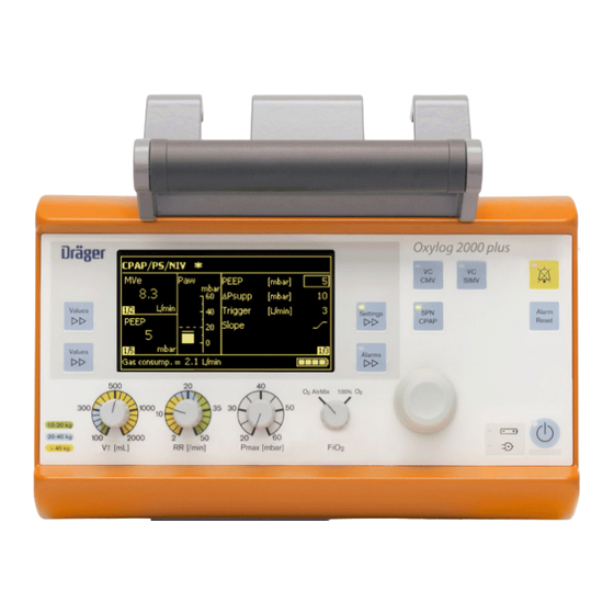
Oxylog 2000 plus
Emergency and Transport Ventilator
WARNING!
The proper servicing and testing of this de-
vice requires a full understanding of this
Technical Documentation. Carefully read
this Technical Documentation and any ap-
plicable Instructions for Use prior to any
use of the device.
Revision 1.0
5503.320
9036363
Advertisement
Chapters
Table of Contents

Related Manuals for Dräger Medical Oxylog 2000 plus


Summary of Contents for Dräger Medical Oxylog 2000 plus
- Page 1 Technical Documentation Oxylog 2000 plus Emergency and Transport Ventilator Revision 1.0 WARNING! The proper servicing and testing of this de- 5503.320 vice requires a full understanding of this 9036363 Technical Documentation. Carefully read this Technical Documentation and any ap- plicable Instructions for Use prior to any...
- Page 2 This page has been intentionally left blank.
-
Page 3: Table Of Contents
Contents Abbreviations Explanation General Symbols and Definitions Notes Function Description General Functional principle Pneumatic assembly Inlet ............................11 Restrictor ..........................11 Sensors and safety functions ....................11 PEEP valve .......................... 12 Ambient pressure conditions ....................13 Electronics Charging Circuit PCB ......................13 Sensor PCB .......................... - Page 4 Contents This page has been intentionally left blank.
- Page 5 Abbreviations This chapter contains a list of the abbreviations used in this manual.
-
Page 6: Explanation
Abbreviations Oxylog 2000 plus Explanation Abbreviation Explanation BTPS English acronym for “Body Temperature, Pressure, Sat- urated” (current conditions in the patient's lung, i.e. body temperature 37 °C, ambient pressure, water-vapor satu- rated gas). English acronym for “Direct Current”. EEPROM English acronym for “Electrically Erasable Programma- ble Read-Only Memory”. -
Page 7: General
General This chapter contains general notes and definitions that are important for the use of this manual. -
Page 8: Symbols And Definitions
General Oxylog 2000 plus Symbols and Defini- tions WARNING A WARNING statement provides important information about a poten- tially hazardous situation which, if not avoided, could result in death or serious injury. CAUTION A CAUTION statement provides important information about a potentially... -
Page 9: Function Description
Function Description This chapter contains descriptions of the device's technical functions. -
Page 10: General
Function description Oxylog 2000 plus General The Oxylog 2000 plus is a time-cycled, volume controlled emergency and transport ventilator with pressure support for patients requiring mandatory or assisted ventilation with a tidal volume from 100 mL upwards. For use by and under supervision of trained health care professionals. -
Page 11: Pneumatic Assembly
Oxylog 2000 plus Function description Pneumatic assembly The following description relates to the pneumatics diagram of the Oxylog 2000 plus. The Control PCB evaluates the measurement signals of the sen- sors and actuates the valves. Inlet The compressed oxygen passes through the filter F1 and the pressure regu- lator DR to the valves V1 to V3. -
Page 12: Peep Valve
Function description Oxylog 2000 plus Fig. 2 Functional principle of the external flow sensor Pressure sensor S5 measures the pressure at the patient. Based on this pressure value, the Control PCB makes calculations including for actuation of the PEEP valve V6. -
Page 13: Ambient Pressure Conditions
Fig. 3 Ventilation valve Ambient pressure Oxylog 2000 plus meters the tidal volume under BTPS conditions. Sensors conditions S7 and S9 measure the ambient pressure. S5 measures the current pressure level in the lung. In this way the Control PCB can balance fluctuating ambient pressure and the BTPS conditions (Body Temperature, Pressure, Saturated. -
Page 14: Sensor Pcb
Function description Oxylog 2000 plus Sensor PCB The Sensor PCB holds all the pressure sensors of the pneumatic system and the internal temperature gauge. The Sensor PCB is the interface for pressure measurement and valve actuation between the pneumatic and electronic sys- tems. -
Page 15: Maintenance Procedures
Maintenance Procedures This chapter describes the measures required to maintain the specified condition of the device. -
Page 16: Replacing The Replaceable Battery
The replaceable battery can be charged by the battery charger station or by the external power supply in the Oxylog 2000 plus. 6. Fit the replaceable battery. 7. Switch on the Oxylog 2000 plus and check the battery capacity indicated on the display. 5503.320... -
Page 17: Replacing The Filter Element
Oxylog 2000 plus Maintenance procedures Replacing the filter 1. Switch off the device. element 2. Remove screws Fig. Fig. 2 Removing the filter element NOTE Note fitting position of filter element. 3. Remove the filter element. 4. Install the new filter element. - Page 18 Maintenance procedures Oxylog 2000 plus This page has been intentionally left blank. 5503.320...
-
Page 19: Schematics And Diagrams
Schematics and Diagrams This chapter contains schematics and diagrams that can be of help when servicing the device. -
Page 20: General
Schematics and diagrams Oxylog 2000 plus General This section presents the diagrams and overviews of the Oxylog 2000 plus, such as the pneumatic components diagram and the block diagram of the electronics. These schematics and diagrams are partly used as reference to the function description. - Page 21 Oxylog 2000 plus Schematics and diagrams Item Designation DC voltage socket Sockets for flowmeter tubes, ventilation tube and compressed gas tube Base plate Fig. 2 Pneumatic components diagram, for legend, see Table 2 Table 2 Legend Fig. 2 Fig. 3...
- Page 22 Schematics and diagrams Oxylog 2000 plus Item Designation Pressure sensor (Paw) to measure pressure close to patient Pressure sensor (delta P) to measure differential pressure at external flow sensor Pressure sensors to measure ambient pressure External flow sensor Safety valve...
- Page 23 Oxylog 2000 plus Schematics and diagrams Fig. 4 Tubing diagram, for legend, see Table 3 Table 3 Legend Fig. 4 Item Designation Sensor PCB Connection block Metering block Tube 4x1 PAE not colored (nc) Tube 2x1.5 Si not colored (nc) Tube 2x1 Si blue (bu), red (rd), orange (og) 5503.320...
- Page 24 Schematics and diagrams Oxylog 2000 plus Fig. 5 Electronics block diagram Fig. 6 Control PCB, for legend, see Table 4 5503.320...
- Page 25 Oxylog 2000 plus Schematics and diagrams Table 4 Legend Fig. 6 Item Designation EEPROM Goldcap capacitor Microcontroller Real-time clock with battery Control PCB mounting screws X120 Connection to signal generator X200 Connection to Sensor PCB X220 Connection to potentiometers X270 Connection to loudspeaker...
- Page 26 Schematics and diagrams Oxylog 2000 plus This page has been intentionally left blank. 5503.320...
-
Page 27: Annex
Annex Parts Catalog This chapter contains a list of the device's orderable parts. Test instructions This chapter contains the measures required to determine the actual condition of the device. - Page 28 This page has been intentionally left blank.
-
Page 29: Parts Catalog
Parts catalog Oxylog 2000 plus Revision: 00 2008-04-28 5503.320... - Page 30 Parts catalog Product concerned Item Remark Order No. Description Qty. Qty.unit Items that are shown in the illustration but are not listed below the illustration are not available as spare parts Revision: 00 Oxylog 2000 plus...
- Page 31 Item Remark Order No. Description Qty. Qty.unit 2M86341 Filter Mat 1.000 2M86733 Battery Lithium-Ionen 1.000 Items that are shown in the illustration but are not listed below the illustration are not available as spare parts Oxylog 2000 plus Revision: 00...
- Page 32 All round Wall Holder USA 1.000 2M86900 Equipment holder 1.000 5704640 Equipment Holder USA 1.000 Items that are shown in the illustration but are not listed below the illustration are not available as spare parts Oxylog 2000 plus Revision: 00...
- Page 33 Hose O2 DISS-DISS gr 3 m spr 1.000 2M86975 Carrying System 1.000 CP-Catalog Accesso./Consumabl. 1.000 Items that are shown in the illustration but are not listed below the illustration are not available as spare parts Oxylog 2000 plus Revision: 00...
- Page 34 Parts catalog Carrying System Item Remark Order No. Description Qty. Qty.unit 8412716 O2-Connector Tube 0,5m 1.000 Items that are shown in the illustration but are not listed below the illustration are not available as spare parts Oxylog 2000 plus Revision: 00...
- Page 35 Order No. Description Qty. Qty.unit 5704500 Gas Supply System 1.000 5704216 All-round Wall Holder 1.000 Items that are shown in the illustration but are not listed below the illustration are not available as spare parts Oxylog 2000 plus Revision: 00...
- Page 36 This page has been intentionally left blank.
-
Page 37: Test Instructions
Test instructions (TL) Oxylog 2000 plus NOTE The procedures described in this Test List can be carried out using commercially available test equipment and tools; however, this Test List does not replace inspections and mainte- nance by the manufacturer. General: All results must be documented in the Test Report. - Page 38 This page has been intentionally left blank. 2 of 20 Oxylog 2000 plus Revision 1.0...
- Page 39 Oxylog 2000 plus device configuration ........
- Page 40 Contents This page has been intentionally left blank. 4 of 20...
-
Page 41: Device Configuration
1 Device configuration 5 of 20... -
Page 42: Oxylog 2000 Plus Device Configuration
Oxylog 2000 plus device configuration 1.1.1 Serial number of the Oxylog (if not otherwise recorded) Action • Read the serial number on the Oxylog 2000 plus (the serial number is located on the name plate). Entry Oxylog 2000 plus serial number [________txt] 1.1.2 Serial number of the power supply unit (if not otherwise recorded) - Page 43 2 Electrical safety 7 of 20...
-
Page 44: Electrical Safety According To Vde 0751/Iec 60601-1
Test instructions (TL) Electrical safety according to VDE 0751/IEC 60601-1 Electrical safety according to VDE 0751/IEC 60601-1 2.1.1 Oxylog 2000 plus - not applicable - 2.1.2 Power supply unit visual check Test The power supply unit, the power supply cord, and the connecting cable to the Oxylog are neither damaged nor contaminated. -
Page 45: Function And Condition Test
3 Function and condition test 9 of 20... -
Page 46: Labels And Instructions For Use
– Check that the wall mount (if present) is attached securely. Action • Latch the Oxylog onto the wall mount (if present). Test – The „external mains power“ LED lights up. Result Condition and function checked. [________OK] 10 of 20 Oxylog 2000 plus Revision 1.0... -
Page 47: Basic Unit Function
Result Function checked. [________OK] 3.2.4 Voltage supply Action • Switch off the device. • Connect the ventilation tube instead of the manometer. Test The „external mains power“ LED lights up green. 11 of 20 Oxylog 2000 plus Revision 1.0... -
Page 48: Supply Pressure/Emergency Air Valve
Ventilation through the emergency air valve is possible. Action • Connect the compressed gas supply. Test – The audible alarm stops. – The yellow alarm LED is no longer lit. – Ventilation is resumed with the previous settings. 12 of 20 Oxylog 2000 plus Revision 1.0... -
Page 49: Safety Valve
• Connect a manometer instead of the ventilation tube (the connection must be tight). Test – The maximum pressure is 85 mbar (110 mbar for the USA unit). Result Function checked. [________OK] Action • Disconnect the manometer and reconnect the ventilation tube. 13 of 20 Oxylog 2000 plus Revision 1.0... -
Page 50: Ventilation
– Flow ramp = not applicable, or standard Test The test thorax inflates to a PEEP pressure of 10 mbar. No self-triggering occurs. Action • Trigger using the test thorax, see the following figure. 14 of 20 Oxylog 2000 plus Revision 1.0... - Page 51 Synchronized mandatory breath Trigger window Test The unit triggers and activates a mandatory breath. At the same moment a „star“ appears on the top line of the display. Result Function checked. [________OK] 15 of 20 Oxylog 2000 plus Revision 1.0...
-
Page 52: Device Handover
Test instructions (TL) Device handover Device handover Entry Place fully functional device at the user's/owner's disposal. [________OK] 16 of 20 Oxylog 2000 plus Revision 1.0... - Page 53 4 Test equipment 17 of 20...
-
Page 54: Test Equipment List
Test instructions (TL) Test equipment list Test equipment list Test equipment Digital manometer up to 1000 mbar Test lung (test thorax) Breathing bag, 2-liter Catheter connector 7 mm Tester for electrical safety test 18 of 20 Oxylog 2000 plus Revision 1.0... -
Page 55: Annex
5 Annex 19 of 20... -
Page 56: Accessing Service Mode
• Now the appropriate test can be selected and activated. To quit service mode switch off the unit. The values set in Customer Service Mode are retained and reactivated every time ventilation is started following power- 20 of 20 Oxylog 2000 plus Revision 1.0... - Page 57 Result 1 Device configuration 3. 1. 3 Carrier system and accessories 1. 1 Oxylog 2000 plus device configuration 3. 2 Basic unit function 1. 1. 1 Serial number of the Oxylog (if not otherwise recorded) 3. 2. 1 Unit test 1.
- Page 58 Subject to change without notice. Will not be replaced in the event of modifications. © Copyright March 2008 by Dräger Medical AG & Co. KG, Lübeck, Germany.
Need help?
Do you have a question about the Oxylog 2000 plus and is the answer not in the manual?
Questions and answers