
Related Manuals for Dräger Medical Oxylog 1000


Summary of Contents for Dräger Medical Oxylog 1000
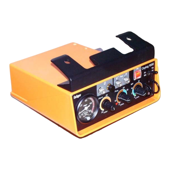
- Page 1 Technical Documentation Oxylog 1000 Emergency Ventilator Revision 4.0 5503.400 9036037 Because you care...
-
Page 3: Table Of Contents
Contents General Symbols and Definitions Notes Function Description General information on the Oxylog 1000 Components of the Oxylog 1000 Pneumatic Control (old Oxylog 1000) Gas Supply ........................... 10 Frequency Control ........................ 11 Air Mix/No Air Mix Selector Switch ..................12 Safety Devices ........................ - Page 4 General points concerning the pressure regulator ..............34 Removing/replacing the pressure regulator ................34 Schematics and Diagrams Flow chart of the Oxylog 1000 (old) Flow chart of the Oxylog 1000 (new) Tubing Diagram of the Oxylog 1000 (old) Tubing Diagram of the Oxylog 1000 (new)
- Page 5 General...
- Page 7 Oxylog 1000 General Symbols and Defini- tions WARNING A WARNING statement provides important information about a poten- tially hazardous situation which, if not avoided, could result in death or serious injury. CAUTION A CAUTION statement provides important information about a potentially...
- Page 8 General Oxylog 1000 Know-how contained in this Technical Documentation is subject to ongoing change through research and development and Dräger Medical reserves the right to make changes to this Technical Documentation without notice. NOTE Unless otherwise stated, reference is made to laws, regulations or stan- dards (as amended) applicable in the Federal Republic of Germany for equipment used or serviced in Germany.
- Page 9 Function Description...
- Page 11 General information The Oxylog 1000 is a time-controlled, volume-constant emergency and trans- on the Oxylog 1000 port ventilator for patients weighing 7.5 kg or above. The Oxylog 1000 has the operating mode: controlled ventilation (IPPV = Intermittent Positive Pres- sure Ventilation).
- Page 12 Function Description Oxylog 1000 Components of the The Oxylog 1000 comprises the following components: Oxylog 1000 – Pressure reducer – ON/OFF switch – Inspiratory/expiratory switching valve – Minute volume control valve – Frequency control – Safety valve – Emergency air valve –...
- Page 13 Oxylog 1000 Function Description Figure 2 Block diagram of the Oxylog 1000 5503.400...
-
Page 14: Pneumatic Control (Old Oxylog 1000)
The compressed gas is supplied from the central supply system (CS) or from an O cylinder with pressure regulator. The operating pressure of the Oxylog 1000 is between 2.7 bar and 6 bar. CAUTION Risk of damage to equipment! Dust, oil and humidity in medical gases may impair the functioning of the equipment or damage it. -
Page 15: Frequency Control
Oxylog 1000 Function Description Frequency Control When the unit is off, driving gas flows via the manifold and through the dosage valve D2 to the 3/2-way valve DMR5 and to DMR6. In consequence, DMR6 switches through and the switching valve WV1 switches to expiration. -
Page 16: Air Mix/No Air Mix Selector Switch
Function Description Oxylog 1000 Air Mix/No Air Mix The setting of the Air Mix/No Air Mix selector switch determines the O con- Selector Switch centration of the supply gas for the patient. When the Air Mix/No Air Mix selector switch is set to "Air Mix", the injector (I) takes in ambient air through the 3/2-way valve (WV2). -
Page 17: Safety Devices
The display range is -10 mbar to 80 mbar. 3.4.3 Emergency Air Valve The spontaneously breathing patient can breathe in ambient air through the emergency air valve if the Oxylog 1000 has failed due to a fault. 5503.400... - Page 18 If the ventilation pressure is higher than 10 mbar, the 3/2-way valve (DMR7) switches. The 3/2-way valves (DMR9, DMR10 and DMR11) vent to atmo- sphere. The visual and audible alarms are suppressed. Ventilation pressure DMR10 DMR11 DMR9 DMR7 Figure 6 Flow chart of the Oxylog 1000: Disconnect Alarm 5503.400...
- Page 19 (DMR8) switches the 3/2-way valve (DMR18). The vent valve (EV) opens the supply gas path to atmosphere. This condition persists until the next inspiratory phase. DMR18 DMR12 DMR13 DMR14 DMR8 Figure 7 Flow chart of the Oxylog 1000: Stenosis alarm 5503.400...
- Page 20 Function Description Oxylog 1000 3.4.6 Gas Supply Failure If the gas supply fails or falls below a defined pressure, the Oxylog 1000 Warning (Pv) delivers two alarms: – Visual alarm indicator "Pv" – Audible alarm (alarm generator) The alarm is triggered under the following conditions: –...
- Page 21 Oxylog 1000 Function Description Alarm Silence When the pushbutton valve (T1) is pressed the 3/2-way valve (DMR15) fills the volume (V3) and activates the 3/2-way valve (DMR16). The 3/2-way valve (DMR17) vents the alarm generator to atmosphere. The alarm generator (L1) is inactive up to the switching point of the volume (V3) (approx.
- Page 22 Function Description Oxylog 1000 Pressure Sensor During ventilation, the pressure sensor controls and switches the stenosis and disconnection of the patient. The pressure sensor comprises two diaphragms. The ventilation pressure acts on the undersides of the diaphragms. The supply pressure (Insp.) is cen- tered on the craters on the pressure sensor during the inspiration phase.
-
Page 23: Pressure Sensor
Oxylog 1000 Function Description Location of Oxylog 1000 (old) Assem- blies Figure 11 Top view of the open Oxylog 1000 (old) Table 1 3/2-way valve (DMR7) Pressure gauge Indicator (Pv) 3/2-way valve (DMR8) Indicator (Silence) Air Mix/No Air Mix Pressure regulator... -
Page 24: Pneumatic Control (New Oxylog 1000)
The compressed gas is supplied from the central supply system (CS) or from an O cylinder with pressure regulator. The operating pressure of the Oxylog 1000 is between 2.7 bar and 6 bar. CAUTION Risk of damage to equipment! Dust, oil and humidity in medical gases may impair the functioning of the equipment or damage it. -
Page 25: Frequency Control
When the unit is switched off, valve WV1 and switch S1 are closed. No venti- lation is carried out and there is no pressure at the frequency control. If Oxylog 1000 is switched on using switch S1, the gas flows through switch S1 and manifold VL1 to DMR1 and DMR2 of the frequency control. -
Page 26: Air Mix/No Air Mix Selector Switch
Function Description Oxylog 1000 Air Mix/No Air Mix The setting of the Air Mix/No Air Mix selector switch determines the O con- Selector Switch centration of the supply gas for the patient. When the Air Mix/No Air Mix selector switch is set to "Air Mix", the injector (I) takes in ambient air through the 3/2-way valve (WV2). -
Page 27: Safety Devices
The display range is -10 mbar to 80 mbar. 5.4.3 Emergency Air Valve The spontaneously breathing patient can breathe in ambient air through the emergency air valve if the Oxylog 1000 has failed due to a fault. 5503.400... - Page 28 The 3/2-way valves (DMR9, DMR10 and DMR11) vent to atmo- sphere. The visual and audible alarms are suppressed. DMR18 Ventilation pressure DMR9 DMR10 DMR11 DMR14 DMR1 DMR3 DMR7 DMR8 DMR12 DMR13 DMR2 DMR15 DMR16 DMR17 Figure 15 Flow chart of the Oxylog 1000: Disconnect alarm 5503.400...
- Page 29 This condition persists until the next inspiratory phase. DMR18 DMR9 DMR10 DMR11 DMR14 DMR1 DMR3 DMR7 DMR8 DMR12 DMR13 DMR2 DMR15 DMR16 DMR17 Figure 16 Flow chart of the Oxylog 1000: Stenosis alarm 5503.400...
- Page 30 Function Description Oxylog 1000 5.4.6 Gas Supply Failure If the gas supply fails or falls below a defined pressure, the Oxylog 1000 Warning (Pv) delivers two alarms: – Visual alarm indicator "Pv" – Audible alarm (alarm generator) The alarm is triggered under the following conditions: –...
- Page 31 Oxylog 1000 Function Description Alarm Silence When the pushbutton valve (T1) is pressed the 3/2-way valve (DMR15) fills the volume (V3) and activates the 3/2-way valve (DMR16). The 3/2-way valve (DMR17) vents the alarm generator to atmosphere. The alarm generator (L1) is inactive up to the switching point of the volume (V3) (approx.
-
Page 32: Pressure Sensor
Function Description Oxylog 1000 Pressure Sensor During ventilation, the pressure sensor controls and switches the stenosis and disconnection of the patient. The pressure sensor comprises two diaphragms. The ventilation pressure acts on the undersides of the diaphragms. The supply pressure (Insp.) is cen- tered on the craters on the pressure sensor during the inspiration phase. -
Page 33: Location Of Oxylog 1000 (New) Assemblies
Oxylog 1000 Function Description Location of Oxylog 1000 (new) Assem- blies Figure 20 Top view of the open Oxylog 1000 (new) Table 2 3/2-way valve (DMR8) Indicator (Silence) On switch 3/2-way valve (DMR7) Alarm control valve Ventilator block Alarm silence... - Page 34 Function Description Oxylog 1000 5503.400...
-
Page 35: Maintenance Procedures
Maintenance Procedures... -
Page 37: General Notes
Maintenance Procedures General notes WARNING Danger of infection! Clean and disinfect the Oxylog 1000, or the rele- vant parts, according to hospital regulations prior to any servicing work or before returning the appliance or parts of it for repair pur- poses. -
Page 38: Pressure Regulator
Remove the scews (1) and washers. • Remve the grub screws (2). • Withdraw the connection socket. Connection socket View of the Oxylog 1000: Removing screws Fig. 1: • Withdraw the drawer unit from the housing of the Oxylog 1000. 5503.400... - Page 39 Maintenance Procedures • Remove the screws (1). Fig. 2: Bottom view of the Oxylog 1000: Removing screws • Detach the small silicone hose (hose connection: supply block to pres- sure gauge) from the hose connection socket of the supply block.
- Page 40 Press in the circlip on the hose connection socket, at the same time with- drawing the PA tube (hose connection: supply block to working block). Supply block Pressure regulator Working block Circlip Pressure gauge Figure 3 View of the drawer unit of the Oxylog 1000 5503.400...
- Page 41 Secure the connection socket for the ventilation hose by the grub screw on the drawer unit of the Oxylog 1000. • Secure the connection socket for the compressed gas hose by the grub screw on the drawer unit of the Oxylog 1000. 5503.400...
- Page 42 Set the Air Mix/No Air Mix selector switch to „No Air Mix“. • Set the main switch of the Oxylog 1000 to „I“. With a flow of approx. 55 L/min (indicated on the flowmeter) the connected pressure gauge shows a pressure of approx. 1.5 bar.
- Page 43 Detach the hose from the pressure gauge and re-connect it to the con- nection socket of the main switch. • Check that there is no leakage in the hose system of the Oxylog 1000. • Install the drawer unit in the reverse sequence into the housing of the Oxylog 1000.
- Page 44 Maintenance Procedures Oxylog 1000 5503.400...
-
Page 45: Schematics And Diagrams
Schematics and Diagrams... -
Page 47: Flow Chart Of The Oxylog 1000 (Old)
Oxylog 1000 Schematics and Diagrams Flow chart of the Oxylog 1000 (old) Figure 1 Flow chart of the Oxylog 1000 (old) 5503.400... - Page 48 Schematics and Diagrams Oxylog 1000 Table 1 Key to flow chart (old) Compressed-gas connection Ventilation valve Restrictor D1 to D7 Pressure gauge DMR1 to DMR18 3/2-way valve Pressure regulator Vent valve Filter Frequency control valve Injector Alarm generator Minute volume control valve...
-
Page 49: Flow Chart Of The Oxylog 1000 (New)
Oxylog 1000 Schematics and Diagrams Flow chart of the Oxylog 1000 (new) Figure 2 Flow chart of the Oxylog 1000 (new) 5503.400... - Page 50 Schematics and Diagrams Oxylog 1000 Table 2 Key to flow chart (new) Compressed-gas connection Ventilation valve Restrictor D1 to D4 Pressure gauge DMR1 to DMR18 3/2-way valve Pressure regulator Vent valve Filter Frequency control valve Injector Alarm generator Minute volume control valve...
-
Page 51: Tubing Diagram Of The Oxylog 1000 (Old)
Oxylog 1000 Schematics and Diagrams Tubing Diagram of the Oxylog 1000 (old) Figure 3 Tubing diagram of the Oxylog 1000 (old) 5503.400... - Page 52 Schematics and Diagrams Oxylog 1000 Table 3 Key to the tubing diagram of the Oxylog 1000 (old) Silence control ON/OFF switch Frequency control Alarm logic Patient block Microswitch pin configuration Volume Pre-tubing Tubing for final assembly on total unit Plug...
-
Page 53: Tubing Diagram Of The Oxylog 1000 (New)
Oxylog 1000 Schematics and Diagrams Tubing Diagram of the Oxylog 1000 (new) Figure 4 Tubing diagram of the Oxylog 1000 (new) 5503.400... - Page 54 Schematics and Diagrams Oxylog 1000 5503.400...
-
Page 55: Annex
Annex Parts catalog Test List... - Page 57 Parts catalog Oxylog 1000 Revision: 2006-03-14 09:56:56 5503.400 Because you care Because you care Emergency Care - Perioperative Care - Critical Care - Perinatal Care - Home Care...
- Page 59 Product concerned Parts catalog Item Qty. Part No. Description Qty. Remark unit 5703300 Caddy 1.000 Items that are shown in the illustration but are not listed below the illustration are not available as spare parts 5503.400 Revision: 2006-03-14 09:56:56...
- Page 60 Accessories/Consumables Parts catalog Item Qty. Part No. Description Qty. Remark unit 5703303 BAG OXYLOG 1000 FOR CADDY 1.000 5703304 BAG OXYLOG 2000 FOR CADDY 1.000 5703305 Bag for CompactCaddy 1.000 5703306 PROTECTION COVER 1.000 5703307 Carrying Belt 1.000 5704216 All-round Wall Holder 1.000...
- Page 61 Caddy Parts catalog Item Qty. Part No. Description Qty. Remark unit 5703310 CLAW_FOR_CADDY 1.000 5703329 PROTECTION BAR HIGH FOR CADDY 1.000 5703328 PROTECTION BAR LOW FOR CADDY 1.000 5703341 CYLINDER FIXATION SET 1.000 5703336 PROTECTION FOOT CADDY 1.000 5703340 GUIDING RAIL SET FOR CADDY 1.000 5703367 PROTECTION STRIP CADDY...
- Page 62 CompactCaddy Parts catalog Item Qty. Part No. Description Qty. Remark unit 5703310 CLAW_FOR_CADDY 1.000 5703333 GUIDING RAIL FOR COMPACTCADDY 1.000 5703335 PROTECTION FOOT Compact CADDY 1.000 Items that are shown in the illustration but are not listed below the illustration are not available as spare parts 5503.400 Revision: 2006-03-14 09:56:56...
- Page 63 Alduk II O2-DM G3/4 2M86632 Alduk II O2-DM Pin Index 2M86678 All-round Wall Holder 5704216 Bag for CompactCaddy 5703305 BAG OXYLOG 1000 FOR CADDY 5703303 BAG OXYLOG 2000 FOR CADDY 5703304 Breathing hose 150 cm 2M86511 Carrying Belt 5703307 COVER...
- Page 65 Test List...
- Page 67 Testing vent valve ........................9 Testing I:E ratio ........................10 Testing ventilatory frequency ....................10 Testing minute volume ......................11 Testing alarm logic and silence control ................. 12 Testing O concentration ...................... 16 Deliver the Oxylog 1000 to the operators ready for operation. Tested...
- Page 68 Checking the I:E Ratio ......................26 Checking the Ventilatory Frequency ..................26 Checking the Minute Volume ....................27 Checking Warning Logics and Silence Control ..............28 Checking the O Concentration .................... 32 Supply Oxylog 1000 to user ready for operation. Tested...
- Page 69 Some function blocks of Oxylog 1000 have been modified. Therefore, this Test List is divided in two parts. Test List 1 (Oxylog 1000 "old") and Test List 2 (Oxylog 1000 "new"). Oxylog 1000 "new" can be recognized by its serial number (ARNL —...
- Page 70 Test List Oxylog 1000 5503.400...
- Page 71 Test List 1 (Oxylog 1000 „old“) Oxylog 1000 Folder no.: Serial no.: 5503.400 ————————— Device location: Issue: ————————— 02.99 This test list can be processed with standard commercially available test aids and tools, but does not replace the inspections and maintenance work carried out by the manufacturer.
- Page 72 Stopwatch Hose clamp Sealing plug This test list can be processed with standard commercially available test aids and tools, but does not replace the inspections and maintenance work carried out by the manufacturer. Page 4 5503.400 Oxylog 1000 Test List...
-
Page 73: Function Tests
Checking general condition of Oxylog 1000 • Check that the accompanying documents are with the Oxylog 1000. • Check the following components for damage: Housing of the Oxylog 1000 Ventilation pressure gauge Ventilation hose Ventilation valve Compressed gas connecting hose 1.5 m... -
Page 74: Testing Supply Pressure And Safety Valve
• Unscrew the compressed gas connecting hose from the connection socket (compressed gas supply). • Remove the drawer unit of the Oxylog 1000 by removing the screws with washers (1). • Remove the screws (2). • Withdraw the connection sockets (ventilation hose and compressed gas supply). - Page 75 0 to 6 bar Main switch Fig. 2: Oxylog 1000 with test set-up: Testing the supply pressure • Set the frequency selector (Freq.) to 10 1/min. • Set the minute volume adjuster (MV) to full right. • Set the ventilation pressure (Paw) to approx. 60 mbar (hPa).
- Page 76 • Close off the hose to the double-membrane relay with the hose clamp; see following illustration. Fig. 3: View of the drawer unit of the Oxylog 1000: Clamping the hose • Set the minute volume adjuster (MV) to full right.
-
Page 77: Testing Vent Valve
Test pressure reducer Flowmeter 0 to 10 L/min Fig. 4: Oxylog 1000 with test set-up: Testing the vent valve • With the test pressure reducer feed a flow of 10 L/min into the connection socket for the ventilation hose. The maximum pressure rise is 8 mbar (hPa) (read off the pressure rise from the pressure gauge of the Oxylog 1000). -
Page 78: Testing I:e Ratio
• Turn the maximum ventilation pressure (Paw) to full right. • Set the Air Mix/No Air Mix selector switch to „No Air Mix“. • Switch on the Oxylog 1000 at the main switch. • Use a stopwatch to determine the I:E ratio. -
Page 79: Testing Minute Volume
Adjustable Flowmeter resistor Fig. 5: Oxylog 1000 with test set-up: Testing the minute volume • Set the ventilation pressure selector (Paw) to full right. • Set the frequency selector (Freq.) to 10 1/min. • Set the minute volume adjuster (MV) variably; see following table. -
Page 80: Testing Alarm Logic And Silence Control
Ventilation valve Test lung Fig. 6: Oxylog 1000 with test set-up to test the supply pressure alarm • Set the minute volume adjuster (MV) to approx. 10 L/min. • Set the frequency selector (Freq.) to 10 1/min. • Set the ventilation pressure selector (Paw) to approx. 40 mbar (hPa). - Page 81 „rot“ indicator (Paw low) lights up. The „Paw low“ switching point is at approx. 10 mbar (hPa). (Read off the switching point from the pressure gauge of the Oxylog 1000 and from the separate pressure gauge). This test list can be processed with standard commercially available test aids and tools, but does not replace the inspections and maintenance work carried out by the manufacturer.
- Page 82 Ventilation hose resistor T-piece Fig. 8: Oxylog 1000 with test set-up: Testing the stenosis alarm • Set the minute volume adjuster (MV) to 10 L/min. • Set the frequency selector (Freq.) to 10 1/min. • Set the Air Mix/No Air Mix selector switch to „Air Mix“.
- Page 83 • Set the frequency selector (Freq.) to 10 1/min. • Detach the test lung from the ventilation valve. The Oxylog 1000 emits an audible alarm. The „Paw low“ indicator lights up red. • During the inhalation phase press the „Alarm silence“ key.
-
Page 84: Testing O Concentration
Vol% Test adapter Test lung Ventilation valve Fig. 10: Oxylog 1000 with test set-up: Testing the O concentration • Set the frequency selector (Freq.) to 10 1/min. • Set the ventilation pressure (Paw) to full right. • Set the Air Mix/No Air Mix selector switch to „Air Mix“. -
Page 85: Deliver The Oxylog 1000 To The Operators Ready For Operation
Deliver the Oxylog 1000 to the operators ready for operation. Tested Date:_ _ _ _ _ _ _ _ _ _ _ _ _ _ _ _ Name:_ _ _ _ _ _ _ _ _ _ _ _ _ _ _ _ This test list can be processed with standard commercially available test aids and tools, but does not replace the inspections and maintenance work carried out by the manufacturer. - Page 86 This test list can be processed with standard commercially available test aids and tools, but does not replace the inspections and maintenance work carried out by the manufacturer. Page 18 5503.400 Oxylog 1000 Test List...
- Page 87 Test List 2 (Oxylog 1000 „new“) Oxylog 1000 File no.: Serial no.: 5503.400 ————————— Installation site: Edition: ————————— 02/2000 This test list can be processed with standard commercially available test aids and tools, but does not replace the inspections and maintenance work carried out by the manufacturer.
- Page 88 Hose clamp Sealing plug This test list can be processed with standard commercially available test aids and tools, but does not replace the inspections and maintenance work carried out by the manufacturer. Page 20 5503.400 Oxylog 1000 Test List 2...
-
Page 89: Functional Tests
Carry out the following functional tests using an O test pressure regulator or the central gas supply system. The supply pressure of Oxylog 1000 is 2.7 bar to 6 bar. This test list can be processed with standard commercially available test aids and tools, but does not replace the inspections and maintenance work carried out by the manufacturer. -
Page 90: Checking The Supply Pressure And The Safety Valve
• Unscrew compressed-gas connecting hose from connecting piece (compressed-gas supply). • To dismount the plug-in unit of Oxylog 1000, remove the screws and washers (1). • Remove the screws (2). • Pull out the connecting piece (ventilation hose and compressed-gas supply). - Page 91 120 L/min "Pv" indicator ON/OFF switch Fig. 2: Oxylog 1000 with test set-up: Checking the supply pressure • Set the frequency adjuster (Freq.) to 10 1/min. • Set the minute volume adjuster (MV) to right limit stop. • Set the airway pressure (Paw) to right end stop.
- Page 92 Reading on the pressure gauge: Pplat = 80 mbar ( 10 mbar). (Peak pressure Pmax <100 mbar) • Place the ON/OFF switch of Oxylog 1000 to position "O". • Remove the hose clamp. • Disconnect the compressed-gas connector from the socket of the central gas supply system/compressed-gas cylinder.
-
Page 93: Checking The Vent Valve
Test pressure regulator Flowmeter 0 to 10 L/min Fig. 4: Oxylog 1000 with test set-up: Checking the vent valve • Using the test pressure reducer, feed a flow of 10 L/min into the connecting piece of the ventilation hose. The increase in pressure should not exceed 8 mbar (hPa) (read pressure on pressure gauge of Oxylog 1000). -
Page 94: Checking The I:e Ratio
• Set the maximum airway pressure (Paw) to right end stop. • Set the Air Mix/ No Air Mix selector to the "No Air Mix" position. • Switch on Oxylog 1000 using the ON/OFF switch. • Use the stopwatch to measure the I:E ratio. -
Page 95: Checking The Minute Volume
Adjustable Flowmeter restrictor Fig. 5: Oxylog 1000 with test set-up: Checking the minute volume • Set the airway pressure adjuster (Paw) to right end stop. • Set the frequency adjuster (Freq.) to 10 1/min. • Set the minute volume adjuster (MV) to various steps, see the following table. -
Page 96: Checking Warning Logics And Silence Control
Test pressure regulator Ventilation valve Test lung Fig. 6: Oxylog 1000 with test set-up for supply pressure warning check • Set the minute volume adjuster (MV) to left limit stop. • Set the frequency adjuster (Freq.) to 10 1/min. • Set the airway pressure adjuster (Paw) to approx. 40 mbar (hPa). - Page 97 (Paw low). The "Paw low" switching point is at approx. 10 mbar (hPa) (read the switching point on the pressure gauge of Oxylog 1000 and on the separate pressure gauge). This test list can be processed with standard commercially available test aids and tools, but does not replace the inspections and maintenance work carried out by the manufacturer.
- Page 98 (Paw high). The "Paw high" switching point is at 50 to 60 mbar (hPa) (read the switching point on the pressure gauge of Oxylog 1000 and on the separate pressure gauge).
- Page 99 Test pressure regulator Ventilation valve Test lung Fig. 9: Oxylog 1000 with test set-up: Checking the alarm sound silence • Set the minute volume adjuster (MV) to 10 L/min. • Set the frequency adjuster (Freq.) to 10 1/min. • Disconnect the test lung from the ventilation valve.
-
Page 100: Checking The O 2 Concentration
Vol% Test adapter Test lung Ventilation valve Fig. 10: Oxylog 1000 with test set-up: Checking the O concentration • Set the frequency adjuster (Freq.) to 10 1/min. • Set the airway pressure (Paw) to right end stop. • Set the Air Mix/ No Air Mix selector to the "Air Mix" position. -
Page 101: Supply Oxylog 1000 To User Ready For Operation
Supply Oxylog 1000 to user ready for operation. Tested Date: _ _ _ _ _ _ _ _ _ _ _ _ _ _ _ _ Name: _ _ _ _ _ _ _ _ _ _ _ _ _ _ _ _ This test list can be processed with standard commercially available test aids and tools, but does not replace the inspections and maintenance work carried out by the manufacturer. - Page 102 This test list can be processed with standard commercially available test aids and tools, but does not replace the inspections and maintenance work carried out by the manufacturer. Page 34 5503.400 Oxylog 1000 Test List 2...
- Page 104 Manufacturer: Support: Dräger Medical b.v. Dräger Medical AG & Co. KG Kanaaldijk 29 Moislinger Allee 53 – 55 D5683 CR BEST D-23542 Lübeck The Netherlands Germany Tel: (++31) 499 331 - 331 Phone: (++49) (0) 1805-3723437 Fax: (++31) 499 331 - 335 Fax: (++49) 451/882 - 3779 Subject to change without notice Will not be replaced in the event of modifications.
Need help?
Do you have a question about the Oxylog 1000 and is the answer not in the manual?
Questions and answers