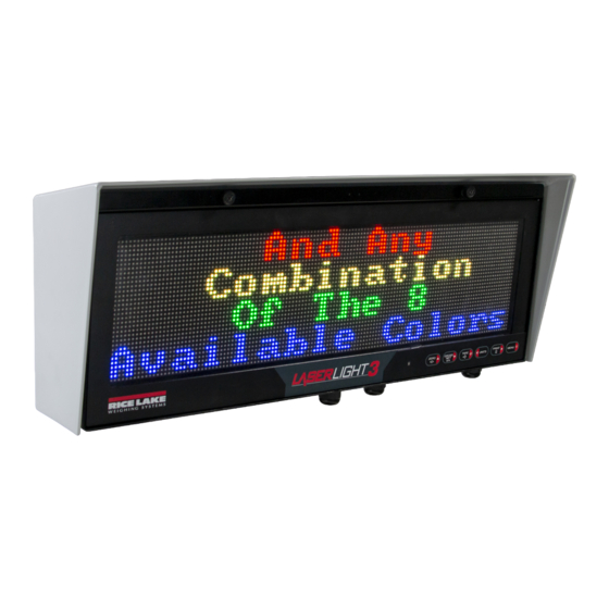
Rice Lake LaserLight3 209118 Installation Setup And Maintenance
Wi-fi module
Hide thumbs
Also See for LaserLight3 209118:
- Technical manual (140 pages) ,
- Quick reference manual (8 pages) ,
- Quick start manual (4 pages)
Table of Contents
Advertisement
Quick Links
LaserLight3
™
Wi-Fi Module Installation Setup
Wi-Fi communication is available to the LaserLight3 with W-Fi communication option kit (PN 209118). This document details the
procedures required to setup the Wi-Fi module.
NOTE: For more information about LaserLight3, see LaserLight3 Large-Display Weight Indicator Technical Manual
(PN 213589) or LaserLight3 Remote Display Technical Manual (PN 214748).
For detailed xPico 200 instructions, visit
Manuals and additional resources are available from Rice Lake Weighing Systems at
Warranty information can be found at
CAUTION: The LaserLight3 does not have a power switch. Before working with the unit, ensure the power cord is
disconnected from the power outlet.
Wi-Fi Module Location
Figure 1
displays the Wi-Fi module installed on a CPU Board.
Wi-Fi Module
September 27, 2022
www.lantronix.com
www.ricelake.com/warranties
Figure 1. Wi-Fi Module Installation Location on CPU Board
Part No.
209103
Wi-Fi Module
203883
Hex Screw M2.5-0.45 x 8
2149009
FL To RP-SMA CABLE
214910
Wi-Fi Antenna
Table 1. Wi-Fi Kit Parts
to view the Series User Guide.
Description
www.ricelake.com/manuals
Qty
1
1
1
1
PN 214366 Rev A
Advertisement
Table of Contents

Subscribe to Our Youtube Channel
Summary of Contents for Rice Lake LaserLight3 209118
- Page 1 (PN 213589) or LaserLight3 Remote Display Technical Manual (PN 214748). For detailed xPico 200 instructions, visit www.lantronix.com to view the Series User Guide. Manuals and additional resources are available from Rice Lake Weighing Systems at www.ricelake.com/manuals Warranty information can be found at www.ricelake.com/warranties CAUTION: The LaserLight3 does not have a power switch.
-
Page 2: Installation
LaserLight3 Wi-Fi Module Installation and Setup Installation CAUTION: The LaserLight3 does not have a power switch. Before working with the unit, ensure the power cord is disconnected from the power outlet. WARNING: Use a wrist strap for grounding to protect components from electrostatic discharge (ESD) when working inside the enclosure or on the front door. - Page 3 8. From bottom of enclosure, install washer and nut (previously removed in Step 6) on end of antenna jack. 9. Thread antenna on antenna jack. Inside Enclosure Bottom of Enclosure Figure 6. Install Antenna and Extension Cable © Rice Lake Weighing Systems ● All Rights Reserved...
- Page 4 LaserLight3 Wi-Fi Module Installation and Setup 10. Attach antenna extension cable to Wi-Fi Module U.FL connector closest to the Wi-Fi module mounting screw. Figure 7. Attach Antenna Extension Cable to Wi-Fi Module 11. Close LaserLight3 enclosure. 12. Connect LaserLight3 power cable to power outlet. Wi-Fi Communications Enabling Wi-Fi Communication This section discusses how to enable Wi-Fi communication on LaserLight3 from the WiFi menu.
- Page 5 3. Enter the default login credentials for the Web Manager. • Username: admin • Password: PASSWORD IMPORTANT: Change default passwords to limit access and enhance security. Figure 11. Web Manager Sign in Prompt © Rice Lake Weighing Systems ● All Rights Reserved...
- Page 6 LaserLight3 Wi-Fi Module Installation and Setup 4. Select Sign in. The Web Manager loads in the browser and the Status page appears. 5. Click QuickConnect at the top of the left navigation panel. Figure 12. Quick Connect Option 6. A list of wireless networks appear. Click the network name intended to connect the wireless module’s Wi-Fi network to. NOTE: If the necessary network does not display, click the Scan button again.
- Page 7 NOTE: If the module’s IP address changed and there is no longer access to the module through the location’s wireless network, connect to the Soft AP and use the Web Manager to learn the new IP Address. For more information, visit www.lantronix.com to view the xPico 200 Series User Guide. © Rice Lake Weighing Systems ● All Rights Reserved...
-
Page 8: Server Configuration
LaserLight3 Wi-Fi Module Installation and Setup Server Configuration The wireless module is configured to be a server by default, with the ability to accept the connection of a client to it. • A Server waits to Accept a connection from a Client •... -
Page 9: Client Configuration
Figure 22. Web Manager with Mode and Host 1 Identified 5. Set the Address and Port as needed to connect to the available server. Figure 23. Web Manager with Address and Port Identified © Rice Lake Weighing Systems ● All Rights Reserved... -
Page 10: Timeout Configuration
LaserLight3 Wi-Fi Module Installation and Setup 6. Click Submit at the bottom of the page to apply and save the settings. A message displays at the top of the page to confirm the changes have been saved. NOTE: While the wireless module’s server is available, it is necessary to adjust the server and client mode settings to allow both to function in unison. -
Page 11: Wireless Module Specifications
• Type Approvals: USA (FCC Part 15), Canada (IC RSS), EU (RED), Japan (MIC), China (SRRC), AU/NZS • Safety: IEC 62368 EN 62368, EN 62311, UL 60950 • RoHS, REACH • FCC ID: R68XPICO200 • Canada IC: 3867A-XPICO200 • CMIIT ID: 2017AJ6663(M) © Rice Lake Weighing Systems ● All Rights Reserved... - Page 12 © Rice Lake Weighing Systems Specifications subject to change without notice. 230 W. Coleman St. • Rice Lake, WI 54868 • USA U.S. 800-472-6703 • Canada/Mexico 800-321-6703 • International 715-234-9171 • Europe +31 (0)26 472 1319 September 27, 2022 PN 214366 Rev A...


Need help?
Do you have a question about the LaserLight3 209118 and is the answer not in the manual?
Questions and answers