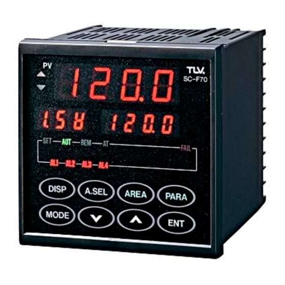
TLV SC-F70 Operating Instructions Manual
Multicontroller auto-tuning pid and heating, cooling pid
Hide thumbs
Also See for SC-F70:
- Operating instructions manual (107 pages) ,
- Operating instructions manual (91 pages)

Related Manuals for TLV SC-F70


Summary of Contents for TLV SC-F70
- Page 1 Manufacturer Multicontroller SC-F70 SC-F70 Auto-Tuning PID Heating, Cooling PID Operating Instructions 172-65281M-00...
-
Page 2: Table Of Contents
7.3 No Error-Displayable Problems ..........92 7.4 Actuator Control Problems ............95 7.5 Sensor Problems ................. 96 7.6 Area Switching External Contact Problems ......99 7.7 External Analog Input Problems ..........100 7.8 Communication Problems ............101 SC-F70 SC-F70 PID Operation Operating Instructions... - Page 3 9.9 Communication Output ............112 9.10 Self-Diagnostic Function ............114 9.11 General Specifications ............115 9.12 Environmental Conditions (Normal Operation) ....115 9.13 Shipping and Storage Conditions ........... 116 10. Product Warranty ................117 SC-F70 SC-F70 PID Operation Operating Instructions...
-
Page 4: Preface
This book will be updated from time to time according to improvements made to the product. But if you find a discrepancy between the descriptions in this book and actual operation, and need help, contact TLV. SC-F70 SC-F70 ... -
Page 5: Checking The Model Code And Accessories
3. A mounting hardware set (2 brackets) 4. The Operating Instructions for Communications (If the communication feature is specified) If the model code differs from your order, or accessories are missing or damaged, please contact TLV immediately. SC-F70 SC-F70 ... -
Page 6: Introduction And Installation
Running in remote mode mode (see page 55). ∑ Runs using alarms, transmission output, or Using other functions communications (see page 62). ∑ Resolves problems you may encounter (see page Troubleshooting 84). SC-F70 SC-F70 PID Operation Operating Instructions... -
Page 7: Setting Feature Jumpers
You can go to "1.3 Attaching to the Panel" directly. 1. The sensor to be used is a pressure transmitter MBS33M (from Danfoss A/S), KH15 (from Nagano Instrument Corp.), or a temperature sensor TR1 obtained from TLV. 2. Remote analog setting operation is not used. Warning: Do not try to use the controller without setting the jumpers correctly according to your mode of operation. - Page 8 Measurement Input Selection Jumper Current Input Voltage Input Voltage Input (Low) Thermocouple (High) [Figure 2. Jumper Setting Guide] 5. Restore the body into the case, and make sure it latches firmly at the stopper. SC-F70 SC-F70 PID Operation Operating Instructions...
-
Page 9: Attaching To The Panel
These figures show the sizes of the controller and the panel cut needed to fit the controller in millimeters (in inches). 12 (0.472") 100 (3.937") Panel Cut Sizes +0.8 +0.031" 25 (0.984") or more (3.622 ) 96 (3.780") -0" SC-F70 SC-F70 PID Operation Operating Instructions... - Page 10 5. Repeat steps 3 and 4 to insert the other bracket on the bottom of the controller and fasten it in place. Fastening Screw Bracket Leg Insert [Figure 1] [Figure 2] SC-F70 SC-F70 PID Operation Operating Instructions...
-
Page 11: Wiring Procedure
If the signal source is grounded, ground only the side closest to the signal source. Controller Signal source b. If the signal source is not grounded, ground the controller side. Signal source Controller SC-F70 SC-F70 PID Operation Operating Instructions... - Page 12 2.) It will take about 3 seconds for the controller to prepare for contact output when the power is turned on. When using the controller to send a signal to an external interlock circuit or other circuits, add a delay relay. SC-F70 SC-F70 ...
- Page 13 * American Wire Gage Warning Do not turn on power supply to the value with which this controller will be used until instructed to do so in section 3.2 "Test Operation". SC-F70 SC-F70 PID Operation Operating Instructions...
- Page 14 MBS33M (from Danfoss A/S) or the temperature sensor TR1 and the control valve CV10 or CV16 shipped with the controller from TLV. (Other possible connections are shown on page16.) a. An example for auto-tuning PID operation...
- Page 15 Measurement Input Terminals Heating Control Output Terminals Current Output 4-20mA Cooling Control Output Terminals Heating Control Valve Current Output Wiring Terminals 4-20mA Cooling Control Valve Remove the cover [Figure 2. Minimum Configuration] SC-F70 SC-F70 PID Operation Operating Instructions...
- Page 16 Cooling Control 4-20mA 0-10V Output (Relay) 0-10mV Terminals 4-20mA 0-100mV Relay contact 0-1V output Thermocouple No.2 Transmission Output Terminals or Cooling Control Output (Current) Terminals Current output 4-20mA [Figure 2. Full Configuration] SC-F70 SC-F70 PID Operation Operating Instructions...
-
Page 17: Using The Panel
This chapter shows how to use the keys and how to read messages displayed on the LEDs, and explains how to enter the necessary data. 2.1 Names and Functions on the Panel : LED Display : Keys SC-F70 FAIL DISP A.SEL AREA... - Page 18 ∑ Refers to or sets a parameter group Parameter key PARA ∑ Registers the new setting Enter key ∑ Increments a setting value Up key ∑ Decrements a setting value Down key ∑ Changes operation modes Mode key MODE SC-F70 SC-F70 PID Operation Operating Instructions...
-
Page 19: Guides For Using Keys
Go to " Key Operation Flow" on page 24. PARA 5) If you want to know or change the mode of operation: Go to " MODE Key Operation Flow" on page 25. SC-F70 SC-F70 PID Operation Operating Instructions... - Page 20 DISP At any time, pressing the key displays the following DISP controller values: a. Auto-tuning PID operation Other than DISP status DISP SC-F70 Measurement value 測定値 Target value 目標値 The first digit indicates the area number. DISP A.SEL AREA PARA...
- Page 21 Heating, cooling PID operation Other than DISP status DISP SC-F70 Measurement value 測定値 Target value 目標値 The first digit indicates the area number. DISP A.SEL AREA PARA MODE DISP SC-F70 Measurement value 測定値 This panel appears only when a soft start time has been Ramp value ランプ値...
- Page 22 ENT number for the operation. Works in LOC mode only (see Note) Other than status A.SEL A.SEL Confirms selection SC-F70 SC-F70 測定値 測定値 Measurement value Measurement value Target value Target value 目標値 目標値...
- Page 23 AREA key, you can display the contents of each item, and in combination with the keys, you can change these values. Other than status AREA AREA SC-F70 SC-F70 SC-F70 Target value New Target value New Target value 新目標値 目標値 新目標値...
- Page 24 12 PARA parameter groups. With the keys and the key, you can change the value of the parameter. ENT Other than PARA status PARA ENT SC-F70 SC-F70 SC-F70 ENT Measurement Decimal point Input Type DISP A.SEL AREA PARA DISP A.SEL...
- Page 25 When current mode is LOC/MAN MODE Display state ∑ selects the SC-F70 SC-F70 Measurement value Measurement value mode shown blinking in the set value LED. Target value ∑ 4 modes available...
- Page 26 MODE Blinking SC-F70 SC-F70 Measurement Value Measurement Value ENT Target Value AT:Blinking DISP A.SEL AREA PARA DISP A.SEL AREA PARA MODE MODE When you press the key while Aton is blinking, Auto-tuning starts. Then the AT lamp blinks to indicate that Auto-tuning is in operation.
- Page 27 When current mode is REM/MAN MODE Display state SC-F70 SC-F70 Measurement value Measurement value Target value ENT AUT REM DISP A.SEL AREA PARA DISP A.SEL AREA PARA MODE MODE [New MODE : REM/AUT] MODE Display state SC-F70 SC-F70 Measurement value...
-
Page 28: Operation
2 Set the controller in LOC mode by referring to " MODE Operation Flow" on page 25. If the REM indicator lamp is off, it is already in LOC mode, so you can omit this step. SC-F70 SC-F70 ... - Page 29 3 Press PARA SC-F70 The display changes to: PV: Group number (PG02) SV: Group name (PVGr) FAIL Symbol: Blank DISP A.SEL AREA PARA MODE 4 Press once. SC-F70 The display changes to: PV: Group number (PG02) SV: Content value of the item No.1,...
- Page 30 6 Press to register the new value. SC-F70 * The decimal point will stop blinking. * If the value contains no decimal fraction, the decimal point next to the last digit will disappear. DISP A.SEL AREA PARA MODE 7 Press to go to the next item.
- Page 31 * By referring to steps 4 to 7 , set all the items for PG03 in the same manner. 10 When item number 8 (time proportional period for cooling) of PG03 is entered, basic parameter setup is complete. Press to exit set-up mode. DISP SC-F70 SC-F70 PID Operation Operating Instructions...
- Page 32 Parameter groups 2 and 3 are mandatory for running the controller, while other groups are optional. This section describes what values should be set for every item in PG02 and PG03. SC-F70 SC-F70 PID Operation Operating Instructions...
- Page 33 * This parameter is displayed only when PVr=1. Designates the decimal Depends position for measurement on order Decimal position input by the number of digits 0 - 3 specifi- after the point. (See Note 3) cations. SC-F70 SC-F70 PID Operation Operating Instructions...
- Page 34 ˚ ˚ 0.0~700.0 0.0~400.0 ˚ ˚ 0.0~999.9 0.0~600.0 20mA Current Input ˚ ˚ 0.0~700.0 0.0~400.0 20mA ˚ ˚ 0.0~600.0 0.0~300.0 ˚ ˚ 0.0~900.0 0.0~500.0 ˚ ˚ 0.0~600.0 0.0~300.0 ˚ ˚ 0.0~999.9 0.0~600.0 SC-F70 SC-F70 PID Operation Operating Instructions...
- Page 35 Output change rate time when control output 0.0 ~100.0 limiter %/second values are changed. * The change rate limiter is OFF when the value is set to 0.0. SC-F70 SC-F70 PID Operation Operating Instructions...
- Page 36 Time proportional output: * CYc is displayed in the period for cooling 1~100seconds heating, cooling PID operation. Note 1: This parameter is set for the heating in the heating, cooling PID operation. SC-F70 SC-F70 PID Operation Operating Instructions...
-
Page 37: Test Operation (Loc/Man Mode)
Note 1: If you use other equipment for the actuator, consider the general-purpose control valve as that equipment, and refer to this description. For details or clarification, contact TLV. Note 2: The heating, cooling PID operation has no Auto-tuning function, and PID constants must be set manually. - Page 38 If either is on, change the mode to LOC/MAN by referring to "Mode Key Operation Flow" on page 25. ∑ Set the control output to 0 %. 1 Press several times until the Symbol DISP SC-F70 Measurement value Display shows OUT. Control Output Symbol Display 2 Press...
- Page 39 ∑ By pressing , adjust the SC-F70 control output value gradually to reach and stay on a target set value in everyday operation. ∑ In the same manner, adjust the control output to obtain DISP A.SEL...
- Page 40 PID setting by referring to "PID Constants Manual Tuning Method" on page 103. In some cases, the optimum PID constants may not be obtainable through the Auto-tuning operation. SC-F70 SC-F70 ...
- Page 41 Step Action ∑ Choose an Area that you are going to set a target value SC-F70 and PID constants for. * Refer to " Key Operation Flow" on page 22. A.SEL DISP A.SEL AREA PARA MODE ∑ Enter the valve control target value into the selected Area.
- Page 42 Step Action ∑ Start Auto-tuning SC-F70 1 Press the Key several times until MODE " " is displayed, blinking. DISP A.SEL AREA PARA MODE 2 Press ∑ Auto-tuning starts with the current Area SC-F70 (preselected). ∑ The AT lamp starts blinking to show that Auto- tuning is running.
-
Page 43: Automatic Operation (Loc/Aut Mode)
(If either or both of them are on, set their modes to MAN and LOC, respectively, by referring to "Mode Key Operation Flow" on page 25.) 2 Press AREA SC-F70 The display should look like the example at right. PV: Area group symbol (AG 1) SV: Target set value (0.00) - Page 44 4 Press to register the new value. * The decimal point will stop blinking. SC-F70 * If the value contains no decimal fraction, the decimal point next to the last digit disappears. * The example shows 120.0 set for target set value.
- Page 45 Step Action ∑ Change the target set value while the operation is in process. SC-F70 AREA 1 Press * The display shown at right appears. DISP A.SEL AREA PARA MODE 2 Press to set the new target value, SC-F70 and press to register the change.
-
Page 46: Area Switching Automatic Operation (Loc/Aut Mode)
Action ∑ Select LOC/MAN mode. * If you need instruction, see page 25. ∑ Set up the areas. * See page 23. SC-F70 1 Press AREA Target value The panel looks like the example at right: PV: Area group symbol (AG 1) - Page 47 Step Action ∑ Select the new area group number you want to use. SC-F70 * Refer to page 22. 1 Press A.SEL * If group 2 is in process, the example shown at right appears. DISP A.SEL AREA PARA PV: Current measurement value (100.0) MODE Symbol: Area number.
- Page 48 * A value of 0.0 sets On and Off actions. 10.0 0.0 to 999.9% (see Note 2) * In the heating, cooling PID operation, a value of 0.0 sets On and Off actions for both heating and cooling. SC-F70 SC-F70 PID Operation Operating Instructions...
- Page 49 P=0.0 or Pc=0.0. Sets manual reset value. Manual reset -5.0 to 105.0% * This item is displayed when (see Note 2) Pπ0.0 and I=0. SC-F70 SC-F70 PID Operation Operating Instructions...
- Page 50 3. The Integral time I, and the Differential time d for cooling are automatically set to the same values as these parameters for heating. 4. Refer to "3.5 Compensation for Control Responsiveness" on page 51 for selecting a value. SC-F70 SC-F70 ...
-
Page 51: Compensation For Control Responsiveness
Step Action 1 Press the key until the Area number you AREA want to set is displayed. SC-F70 2 Press the key until " " is displayed. DISP A.SEL AREA... -
Page 52: Pid Constants Fine-Tuning Method
1. The first peak fluctuation of the measured value after controlling caused by external disturbance decreases. 2. Oscillation becomes suppressed. The oscillation damping ratio increases, but it decreases again if the D value is increased too much. 3. The oscillation cycles shorten. SC-F70 SC-F70 PID Operation Operating Instructions... -
Page 53: Pid Constants Setting And Control Operation
3 PID operation (Pπ0.0*, Iπ0*) 100% Control output HS : hysteresis db : dead zone Mr : manual reset * Optimum values for P, I, and D should be set by Auto-tuning or manual tuning. SC-F70 SC-F70 PID Operation Operating Instructions... - Page 54 4 heating PID+cooling ON-OFF operation (Pπ0.0*,Iπ0*, Pc=0.0) 100% Control output 0% 5 heating PID+cooling PID operation (Pπ0.0*,Iπ0*, Pcπ0.0*) 100% Control output 0% * Optimum values for P, I, D, and Pc should be manually tuned. SC-F70 SC-F70 PID Operation Operating Instructions...
-
Page 55: Remote Operation (Rem/Aut Mode)
Improper setting of the parameter PG05/AiGr may produce unexpected controller output. 3. Connect the analog input device by referring to the following figure and tables. External contacts Back panel terminals No voltage contact 0-5V,1-5V Analog input signal 0-10V,0-20mA 4-20mA SC-F70 SC-F70 PID Operation Operating Instructions... - Page 56 Contact Action Mode Switches To Close to open LOC mode (about 2 seconds later) No.12 - No.13(Di1) Open to close REM mode (about 2 seconds later) Analog input signal No.15 - No.16 SC-F70 SC-F70 PID Operation Operating Instructions...
- Page 57 Note: The analog input signal fluctuation must be less than 0.1 % F.S. If the fluctuation exceeds this, the controller may accept the fraction as a new set value, which can cause a hunting problem in the valve actuator. SC-F70 SC-F70 ...
-
Page 58: Remote Area Switching Operation
LOC/REM SW MAN/AUT SW 8 Di1 COM (—) COM (—) COM (—) Area 4 Di2 4 Di2 4 Di2 Area Area 2 Di3 2 Di3 2 Di3 1 Di4 1 Di4 1 Di4 SC-F70 SC-F70 PID Operation Operating Instructions... - Page 59 1. The new value given by the external contacts becomes effective after about 2 seconds. 2. Mode switching requests are honored by detecting a status change. 3. An area number is determined only by the status of the contact points. SC-F70 SC-F70 ...
- Page 60 13 - 16 (Di4) Note: 1. The new value given by the external contacts becomes effective after about 2 seconds. 2. An area number is determined only by the status of the contact points. SC-F70 SC-F70 PID Operation Operating Instructions...
- Page 61 MAN Æ AUT switching (External contact) 1 If Dil contact point is open, close it; if closed, open and close it. ∑ Once this procedure is completed, the new area number set by the external contacts is used by the controller. SC-F70 SC-F70 ...
-
Page 62: Using Other Functions
*1: Cannot be used if the control output or the heating control output is a relay contact output. *2: Cannot be used if the cooling control output is a relay contact output in the heating, cooling PID operation. SC-F70 SC-F70 ... - Page 63 3. Alarm relay contact is open for no alarm state, and is closed when alarm conditions are met. 4. Inputs to be monitored are measurement input, analog setting input, and area switching input. SC-F70 SC-F70 PID Operation Operating Instructions...
- Page 64 Timer: Delays the alarm output activation. Hysteresis: Delays the alarm output deactivation. Use of these timer and hysteresis delays provides additional control to prevent frequent alarm activation due to the unstable pressure. SC-F70 SC-F70 PID Operation Operating Instructions...
-
Page 65: Using The Transmission Output
*1: If the control output is a current output, the third transmission output cannot be used. *2: If the cooling control output is a current output in the heating, cooling PID operation, the second transmission output cannot be used. SC-F70 SC-F70 PID Operation Operating Instructions... -
Page 66: Using The Communications Function
∑ EIA RS-485: 2-wire multidrop connection ∑ EIA RS-232C: 3-wire point-to-point connection See page 112 for other specifications. For operation details, refer to the "SC-F70 Multicontroller Operating Instructions for Communications" booklet. 5.4 Using Other Convenient Features The following commonly used features enable more sophisticated operation. -
Page 67: What Happens When Power Is Lost
The controller operation is the same as when the control output is not available. To shut down the control fluid supply when the controller power is lost, install an additional shutdown valve which closes when power is lost. SC-F70 SC-F70 ... -
Page 68: Summary Of Parameter Groups And Areas
6.1 Parameters Parameters are grouped in 10 related families (PG02 through PG10, and PG12). To change the value in the parameters, you must set the controller in MAN mode, if in AUT mode, precedently. SC-F70 SC-F70 PID Operation Operating Instructions... - Page 69 * This parameter is displayed only when PVr=1. Designates the decimal Depends position for measurement on order Decimal position input by the number of digits 0 - 3 specifi- after the point. (See Note 3) cations. SC-F70 SC-F70 PID Operation Operating Instructions...
- Page 70 ˚ ˚ 0.0~700.0 0.0~400.0 ˚ ˚ 0.0~999.9 0.0~600.0 20mA Current Input ˚ ˚ 0.0~700.0 0.0~400.0 20mA ˚ ˚ 0.0~600.0 0.0~300.0 ˚ ˚ 0.0~900.0 0.0~500.0 ˚ ˚ 0.0~600.0 0.0~300.0 ˚ ˚ 0.0~999.9 0.0~600.0 SC-F70 SC-F70 PID Operation Operating Instructions...
- Page 71 Output change rate time when control output 0.0 ~100.0 limiter values are changed. %/second * The change rate limiter is OFF when the value is set to 0.0. SC-F70 SC-F70 PID Operation Operating Instructions...
- Page 72 Time proportional output: * CYc is displayed in the period for cooling 1~100seconds heating, cooling PID operation. Note 1: This parameter is set for the heating in the heating, cooling PID operation. SC-F70 SC-F70 PID Operation Operating Instructions...
- Page 73 (See Note 6) and the time the alarm turns on. Selects the type of alarm for Type for Alarm 4 0-13 AL4. (See Note 7) (Note 1) SC-F70 SC-F70 PID Operation Operating Instructions...
- Page 74 6. This item is not displayed, if the control output (the heating control output when in the heating, cooling PID operation) is a relay output. 7. This item is not displayed if the cooling control output is a relay output in the heating, cooling PID operation. SC-F70 SC-F70 ...
- Page 75 0: No tracking replaced with LOC mode Remote setting 1: Tracking target settings when the mode tracking is changed from REM to LOC. Note: Use the same unit specified in the measurement input unit. SC-F70 SC-F70 PID Operation Operating Instructions...
- Page 76 2: Target setting Type for transmission when the cooling control 3: Control output output 2 output is a current output in 4: Cooling control the heating, cooling PID output operation. (Note 1) SC-F70 SC-F70 PID Operation Operating Instructions...
- Page 77 Ao3=3 or 4: limit 0.0~100.0% (3.AL <3.AH) 3.AH Notes: 1. The cooling control output can be selected in the heating, cooling PID operation. 2. Use the same unit specified in the measurement input unit. SC-F70 SC-F70 PID Operation Operating Instructions...
- Page 78 On-Off action (P=0.0). 2. When 1, 2, or 3 is specified in this item, and an Auto-tuning error occurs, an error code (E11 to E13) is displayed, until the key is pressed. DISP SC-F70 SC-F70 PID Operation Operating Instructions...
- Page 79 Down deviation 0: All unlocked Selects which settings are 1: Parameter locked. Setting lock settings locked 2: All locked Note: Use the same unit specified in the measurement input unit. SC-F70 SC-F70 PID Operation Operating Instructions...
- Page 80 2. Baud rates Setting Parity bits Data bits Stop bits None 0: 1200 bps None 1: 2400 bps Even 2: 4800 bps Even 3: 9600 bps 4: 19200 bps None None Even Even SC-F70 SC-F70 PID Operation Operating Instructions...
-
Page 81: Areas
* A value of 0.0 sets On and Off actions. 10.0 0.0 to 999.9% (see Note 2) * In the heating, cooling PID operation, a value of 0.0 sets On and Off actions for both heating and cooling. SC-F70 SC-F70 PID Operation Operating Instructions... - Page 82 P=0.0 or Pc=0.0. Sets manual reset value. Manual reset -5.0 to 105.0% * This item is displayed when (see Note 2) Pπ0.0 and I=0. SC-F70 SC-F70 PID Operation Operating Instructions...
- Page 83 3. The Integral time I, and the Differential time d for cooling are automatically set to the same values as these parameters for heating. 4. Refer to "3.5 Compensation for Control Responsiveness" on page 51 for selecting a value. SC-F70 SC-F70 ...
-
Page 84: Troubleshooting
Generally, the controller system problems are categorized as follows: Controller problem Actuator control problem Sensor problem Remote external input problem Communication problem Each of them has the characteristics described in the following pages. SC-F70 SC-F70 PID Operation Operating Instructions... - Page 85 There are three types of external contact problems. ∑ External contact or wiring problems ∑ External analog input device or wiring problems ∑ Setting errors or usage outside of specifications SC-F70 SC-F70 PID Operation Operating Instructions...
- Page 86 No error-displayable Was controller controller problem panel display lit ? Go to page 92 Can you read the panel display ? Did the FAIL Error-displayable lamp come on ? controller problem Go to page 89 Continued on next page SC-F70 SC-F70 PID Operation Operating Instructions...
- Page 87 Did any error ∑ Blinking display controller problem appear ? ∑ FAIL lamp on Go to page 89 Does system No error-displayable operate correctly controller problem as set in area ? Go to page 92 Continued on next page SC-F70 SC-F70 PID Operation Operating Instructions...
- Page 88 ? ∑ FAIL lamp on Go to page 89 External analog Does the operation setting input problem work correctly ? Go to page 100 Use the communication function (See SC-F70 Only when this Communication Manual). option is installed. Does Communication communication problem work OK ? Go to page 101...
-
Page 89: Error Displayable Controller Problems
7.2 Error-Displayable Controller Problems Check the error code and its displayed location, and take action. SC-F70 Measurement Display Set value Symbol FAIL Indicator lamp DISP A.SEL AREA PARA MODE Where Error Description Error Code Action The sensor signal is 100% to 105% or -5 to 0% of 1. - Page 90 The error message is displayed until the DISP is pressed; operation will follow the selection made for operation in the event of an Auto-tuning error (See parameter PG08 on page 78). SC-F70 SC-F70 PID Operation Operating Instructions...
- Page 91 All controller outputs are turned off. ROM error or CPU power error or watchdog FAIL timer error occurred. All other indicators are lights turned off. All controller outputs are also turned off. SC-F70 SC-F70 PID Operation Operating Instructions...
-
Page 92: No Error-Displayable Problems
An analog setting input signal Insert an isolator, etc. to ensure that has been entered in parallel to an insulated analog setting signal is multiple SC-F70 units using a input to each unit. grounded thermocouple. Measured value Make sure the setting for... - Page 93 48. SC-F70 SC-F70 PID Operation Operating Instructions...
- Page 94 Make sure the type of alarm, Reset these values to the ones you faulty. excitation, hysteresis setting, want by referring to "Using the or alarm timer are selected Alarm" on page 64. correctly. SC-F70 SC-F70 PID Operation Operating Instructions...
-
Page 95: Actuator Control Problems
Note: This section describes an example with a general-purpose control valve used as the actuator. If you are using a different actuator, contact TLV. Analysis Actions ∑ When the voltages measured Measure the controller output to the actuator while running test operation in MAN mode. -
Page 96: Sensor Problems
∑ When the measured values displayed are different from the actual sensor reading, use this analysis and action. * This section describes an example with a pressure transmitter (MBS33M, from Danfoss A/S) and a temperatute sensor (TR1) obtained from TLV. If you are using different equipment, contact TLV. Analysis Actions ∑... - Page 97 400 kPa abs DC 3V ∑ If the measured value is not Take the actions in the right column depending on the stable, check the signal wire shielding and the controller measurement results. grounding. SC-F70 SC-F70 PID Operation Operating Instructions...
- Page 98 4. Remove the sensor cables from the sensor terminal, and have the sensor cable serviced. measure the sensor resistance between A and B as shown. If the resistance is not Sensor Terminal adequate, replace the sensor. SC-F70 SC-F70 PID Operation Operating Instructions...
-
Page 99: Area Switching External Contact Problems
1. Ensure your controller is equipped with the remote area switching feature. function cannot be used. Model code = SC-F70- The second-to-last digit should be a D. ∑ If the setting is incorrect, 2. Check that the setting in item 1 of the parameter PG06 correct it. -
Page 100: External Analog Input Problems
1. Ensure your controller is equipped with the remote analog input feature. function cannot be used. Model code = SC-F70- The second-to-last digit should be an A. ∑ If the settings are incorrect, 2. Check that the settings in all items of the parameter correct them. -
Page 101: Communication Problems
∑ If the code is different, this 2. Ensure that your controller is equipped with the function cannot be used. communication functions. Model code = SC-F70- 1 (RS-232C) SC-F70- 4 (RS-422A) SC-F70- 5 (RS-485) The last digit should be either 1, 4, or 5. -
Page 102: Other Problems
∑ If the symptom does not recur, 3. Change the PID constants by referring to "3.6 PID Constants Fine Tuning Method" on page 52, and leave the new setting and observe whether the symptom improves. continue monitoring. SC-F70 SC-F70 PID Operation Operating Instructions... -
Page 103: Pid Constants Manual Tuning Method
L and T (sec). control output infrection point 7. Specify the value variation as DPV, △PV and define the process gain Kp using time the following equation: ¥ 100 ¥ Kp = (Measurement range) SC-F70 SC-F70 PID Operation Operating Instructions... - Page 104 AUT mode and verify its control responsiveness. Note: If the results do not meet your requirements, change the PID values by referring to "3.6 PID Constants Fine Tuning Method" on page 52. SC-F70 SC-F70 PID Operation Operating Instructions...
-
Page 105: Ultimate Sensitivity Method
AUT mode and verify its control responsiveness. Note: If the results do not meet your requirements, change the PID values by referring to "3.6 PID Constants Fine Tuning Method" on page 52. SC-F70 SC-F70 PID Operation Operating Instructions... -
Page 106: Specifications
Within ± 4 V Input voltage range: 4. DC voltage (HIGH) input Input values: 0-5 V, 1-5 V, 0-10 V Input impedance: Approximately 1 MW Within ± 12 V Input voltage range: SC-F70 SC-F70 PID Operation Operating Instructions... -
Page 107: Settigns
AREA switching method: * Using keys on front panel * Through external contacts when model is equipped with area switching external input feature * Through communications when model is equipped with communication feature SC-F70 SC-F70 PID Operation Operating Instructions... -
Page 108: Control Operation
(2) Control calculation period: 0.25 second 9.5 Control Output 9.5.1 First Control Output (OUT1) This is the control output in the Auto-tuning PID operation, and the heating control output in the heating, cooling PID operation. SC-F70 SC-F70 PID Operation Operating Instructions... - Page 109 * When a current output is selected for the second control output type, the second control output becomes the alarm output 4 (AL4). * Either the DC current output or the relay output can be specified as the second control output type. SC-F70 SC-F70 ...
-
Page 110: Alarm Ouput
3. Electrical service life 1) AL1 and AL2: 50,000 times minimum under rated load 2) AL3 and AL4: 300,000 times minimum under rated load (8) Alarm display: Red surface-emitting LED (AL1 to AL4) SC-F70 SC-F70 PID Operation Operating Instructions... -
Page 111: Transmission Output
2. Input method used: No-voltage type contact Resistance when OPEN: 500 kW minimum Resistance when CLOSED: 10W maximum 3. Voltage when OPEN: DC 5 V 4. Functions (selectable): Operation mode switching, MAN/AUT or LOC/REM SC-F70 SC-F70 PID Operation Operating Instructions... -
Page 112: Communication Output
Note: These values may differ slightly depending on cables and other factors in the surrounding environment. (4) Synchronization: Start-stop synchronization (5) Communication speed: 1200 bps, 2400 bps, 4800 bps, 9600 bps, or 19200 bps (6) Data format 1. Start bit: SC-F70 SC-F70 PID Operation Operating Instructions... - Page 113 2. RS-485: 32 units including host computer 3. RS-232C: 1 unit (8) Communication code: ASCII (JIS) 7-bit code (9) Terminals 1. RS-422A, 4-wire Terminal No. Signal SC-F70 <Signal Direction> Host Remarks ← R(A) Receive data ← R(B) Receive data T(A) →...
-
Page 114: Self-Diagnostic Function
1. When the FAIL lamp lights: All output is turned OFF Note: The alarm function can be used to detect the FAIL condition. 2. When an input error occurs: Depends on the operation selection in the event of an input error SC-F70 SC-F70 PID Operation Operating Instructions... -
Page 115: General Specifications
(8) Weight: Approximately 500 g (1.1 lb) (9) Accessories: A pair of mounting brackets 9.12 Environmental Conditions (Normal Operation) (1) Ambient temperature: 0 to 50˚C (32 to 122˚F) SC-F70 SC-F70 PID Operation Operating Instructions... -
Page 116: Shipping And Storage Conditions
9.13 Shipping and Storage Conditions (1) Temperature: -20 to 70˚C (-4 to 158˚F) (2) Humidity: 95% RH maximum, no dew (3) Vibration: 5 m/sec (16.4 ft/sec (4) Shock: 100 m/sec (328 ft/sec SC-F70 SC-F70 PID Operation Operating Instructions... -
Page 117: Product Warranty
One year following product delivery. 2. Warranty Coverage TLV Co., Ltd. warrants this product to the original purchaser to be free from defective materials and workmanship. Under this warranty the product will be repaired or replaced, at our option, without charge for parts or labor. - Page 118 Kakogawa, Hyogo 675, Japan Tel: [81]-(0)794-27-1818 Fax: [81]-(0)794-25-7033 Manufacturer 881 Nagasuna, Noguchi, Kakogawa, Hyogo 675, Japan Tel: [81]-(0)794-22-1122 Fax: [81]-(0)794-22-0112 Home Page:http://www.tlv.com For Service or Technical Assistance: Contact your representative or your regional office In North America: 13901 South Lakes Drive Charlotte, NC 28273-6790 U.S.A.
- Page 119 SC-F70 SC-F70 PID Operation Operating Instructions...
Need help?
Do you have a question about the SC-F70 and is the answer not in the manual?
Questions and answers