Table of Contents
Advertisement
Quick Links
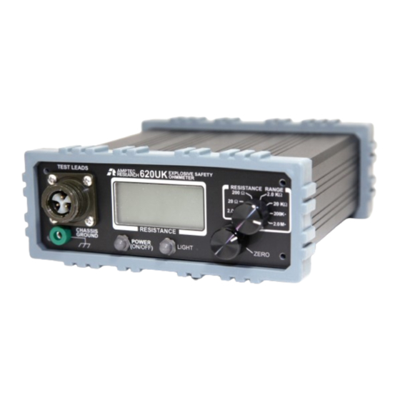
AMPTEC 620UK-4
SAFETY OHMMETER
MAINTENANCE and OPERATION MANUAL
V4 ( 4 Wire Kelvin Version)
Amptec Research Corp.
PHONE (512) 858-4045;
FAX (512) 858-4340; TOLL FREE IN THE USA
800-350-5105
website http://www.amptec.com
13231 Rooster Springs Rd.
Austin, TX 78737 USA
T: +1 (512) 858-4045 // E: info@amptec.com
Advertisement
Table of Contents

Related Manuals for Amptec Research 620UK-4


Summary of Contents for Amptec Research 620UK-4
- Page 1 AMPTEC 620UK-4 SAFETY OHMMETER MAINTENANCE and OPERATION MANUAL V4 ( 4 Wire Kelvin Version) Amptec Research Corp. PHONE (512) 858-4045; FAX (512) 858-4340; TOLL FREE IN THE USA 800-350-5105 website http://www.amptec.com 13231 Rooster Springs Rd. Austin, TX 78737 USA T: +1 (512) 858-4045 // E: info@amptec.com...
-
Page 2: Table Of Contents
TABLE OF CONTENTS SECTION A: RECEIVING AND INITIAL INSPECTION A-1Introduction to the AMPTEC 620UK Safety Ohmmeter (p. 4) A-2Unpacking and Inspection (p. 4) A-3 DC Battery Power Requirements (type AA) (p. 5) A-4Setup and Preparation for Use (p. 6) SECTION B: 620UK EXPLOSIVE SAFETY OHMMETER SPECIFICATIONS Table B-2. - Page 3 SECTION E: MAINTENANCE, REPAIR, AND CALIBRATION General (p. 15) Troubleshooting only by Authorised Personnel (p. 15) Circuit Board Operation Overview (p. 15) Ohmmeter Assemby/Dissasembly Diagram (p.16) Block Diagram and Circuit Description (p. 17) E-5.1 Principle of Operation E-6 Trouble-shooting or Diagnostic Test Procedure for AMPTEC 620UK Ohmmeter Printed Circuit Board (p.18) E-6.1 Current Source PCB Diagnostic Routine (p.
-
Page 4: A-2Unpacking And Inspection
SECTION A - RECEIVING AND INITIAL INSPECTION A-1. Introduction - AMPTEC 620UK The AMPTEC 630, 640 and now the AMPTEC 620 Series Failsafe Ohmmeters have become the standard in the Safety Ohmmeter/Igniter Circuit Test industry. They provide extremely safe and reliable resistance testing of explosive or volatile devices. -
Page 5: Dc Battery Power Requirements (Type Aa)
If the unit fails to operate or fails to meet the performance specifications of Section B, notify the carrier's agent and your nearest AMPTEC Sales Agent’s Office (i.e. see our website at http://www.amptec.com for contact info). Retain the shipping carton for the carrier's inspection. DO NOT return equipment to AMPTEC RESEARCH or any of its sales offices without first obtaining an (RMA) Return Material Authorization number. - Page 6 The AMPTEC 620UK Explosive Safety Ohmmeter is “4-Wire” Kelvin version ohmmeter. See diagram below. LEAD RESISTANCE FAIL SAFE OHMMETER DC CURRENT LIMITED CONSTANT CURRENT SOURCE VOLTAGE LIMITING RESISTOR * contact resistance LEAD RESISTANCE ( V4 Users only) Disregard the unit's front panel “ZERO” knob. It was only intended for the 2 Wire ohm version of the AMPTEC 620UK Ohmmeter.
-
Page 7: Section B: 620Uk Explosive Safety Ohmmeter Specifications
SECTION B - 620UK EXPLOSIVE SAFETY OHMMETER - SPECIFICATIONS ___________________________________________________ 620UK Resistance Range/Resolution Nominal Test Current/Fail-Safe Current * Actual fail-safe currents vary with each instrument and may be ±20% from the typical value. Table B-2. Specifications (for 1 year @25°C ± 10°C) Accuracy: 2.0 ohm range . -
Page 8: Section C: Replacement And Accessory Items
SECTION C: REPLACEMENT & ACCESSORY ITEMS Contact the sales dept. at AMPTEC RESEARCH for AMPTEC 620UK (V4) compatible test leads and accessories. The AMPTEC 620UK Explosive Safety Ohmmeter is available with a transit case (OP-101) with shoulder strap and front panel NSN connector compatible multi-function test lead set . -
Page 9: Section D: Operation, Function And Use
SECTION D : OPERATION , FUNCTION, AND USE D-1 GENERAL USE The AMPTEC 620UK is designed to operate for approximately 1 year under normal use before the 4 “AA” batteries need to be replaced. The “LOW BAT” indicator on the units LCD Display is factory adjusted to come on with the internal batteries need to be replaced. -
Page 10: D-2.2 Main Power Switch
D-2.5 Resistance Range Selection The AMPTEC RESEARCH 620UK Explosive Safety ohmmeter is fitted with seven resistance ranges. The lowest resistance range ( 2.0 Ohm ) provides resistance measurement capability from zero ohms up to the level of i.9999 Ohms Fullscale. - Page 11 AMPTEC 620UK Front Panel Test Connector ( V4 version shown) Pin A= V High Pin B= I High Pin C= I Low Pin D= V Low Pin E= Chassis Ground (shield) The AMPTEC 620UK Explosive Safety Ohmmeter Front Panel Test Lead Connection uses pin A of the connector is the Voltage High, pin B is I (current) High, pin C is Current Low and pin D is Voltage low.
- Page 12 error or offset, if not compensated for. The front panel “ZERO” knob allows the AMPTEC 620UK Safety Ohmmeter user to zero out most typical test lead resistance. That is - T he zero knob is for “zeroing or nulling out” the typical 100-150 milliohms worth of test lead wiring resistance and contact resistance offset - which is determined when the leads are shorted (see below).
-
Page 13: D-2.6 Zero Operation
ZERO (continued) However if the test leads are changed (i.e from clips to probes) we recommend resetting the zero on the AMPTEC 620UK Ohmmeter. After the “ZERO” adjustment of the test leads is accomplished, the AMPTEC 620UK Ohmmeter is ready to connect to the resistance under test. -
Page 14: 620Uk Metal Chassis Description
D-4 620UK METAL CHASSIS DESCRIPTION The AMPTEC 620UK Ohmmeter chassis (case) is an aluminum enclosure that also acts as a Faraday cage surrounding the unit's internal electronics. The Chassis (enclosure) has a front panel earth/ground jack which enables it to be earthed to the same electrical potential as the equipment which the product will be testing. Internal AMPTEC 620UK Ohmmeter earthing connects all rear panel, battery compartment, PCBs and front panel aluminum shield behind the front panel labeling, are connected to the chassis and chassis ground front panel jack. - Page 15 E-1. General The AMPTEC RESEARCH 620UK Ohmmeter is shown in PCB block diagram form on page 17. The AMPTEC 620 Series Igniter Tester uses modern solid-state semiconductors exclusively and digital CMOS circuits extensively to minimize power requirements and make battery operation useful and practical. AMPTEC also maintains a 620UK spare PCB inventory and it’s customer service department can also provide...
- Page 16 Circuit Board Slot Circuit Board Slot E-4 AMPTEC 620UK Ohmmeter Assembly/Disassembly Diagram The AMPTEC 620UK Ohmmeter Current Source PCB and DVM PCB are epoxy conformal coat encapsulated both the top and bottom side of each PCB. This PCB encapsulation provides excellent humidity resistance, moisture condensation resistance, dust and dirt PCB contamination resistance.
- Page 17 A-5 BLOCK DIAGRAM AND CIRCUIT DESCRIPTION The AMPTEC 620UK Explosive Safety Igniter Tester is a portable digital milli-ohmmeter specifically designed for ultra-safe resistance testing on bonds in a highly flammable fuel air environment. With 4 1/2- digit resolution and a low Ohm range of 2.0 Ohms full-scale, the AMPTEC 620UK Ohmmeter provides ordnance safe resistance measurements and viewing even in direct sunlight.
- Page 18 Use only the specified component or its exact equivalent. Spare replacement PCBs can be ordered from your nearest AMPTEC RESEARCH Service Center or directly from the factory by referring to the AMPTEC Stock Number listed in the Parts Lists section at the back of this manual.
- Page 19 A-8 620UK Calibration Adjustment Procedure. All the 620UK Ohmmeter calibration adjustments (trimpots) are located on the DVM PCB (top slot - see diagram below). The calibration adjustments must take place with the 620UK Ohmmeter Front panel and all PCBs assemblies must be out of the 620UK chassis. Place the 620UK in the 20 Ohm range and short the measurement test leads together.
- Page 20 E-9 Battery Compartment Design and Description The battery compartment of the 620UK Ohmmeter has been designed in accordance with British Defence Standard 66-31 and is separate to the main electronics. The battery compartment houses four AA-size batteries and holder. The supply wires connect the batteries to the Printed Circuit Boards inside the Ohmmeter passes through a small hole in the side of the battery compartment.
- Page 21 E-10 Low Battery Indicator: The Low Battery Indicator is factory adjusted to have the low battery indicator come on at 4.50 VDC. This is a one time adjustment that is set for the life of the AMPTEC 620UK. Replacement batteries must be either of the following: Duracell Plus Type MN1500, Eveready Silver Seal type R65 or Eveready Ultra Plus, Silver Seal type R6F4UP, Varta Type 3006, or GP Type GP15 to maintain the Eex- ib-IIC-T4 Intrinsically Safe Certification.
- Page 22 A full 16 page copy of the MIL STD 810, A copy of the US NAVAL ORDNANCE SAFETY Board Method 511 Rev F Explosive and Volatile Atmosphere Approval of AMPTEC 620UK Ohmmeter on Evolved Sea Test successfully performed at +°50 C is available Sparrow Missile squibs is available ( www.amptec.com/tech.htm (call for password)
Need help?
Do you have a question about the 620UK-4 and is the answer not in the manual?
Questions and answers