Table of Contents
Advertisement
T.O 33D5-14-52-1
OPERATION / MAINTENANCE MANUAL
AMPTEC RESEARCH MODEL 620A-4
FAILSAFE DIGITAL OHMMETER/
IGNITER CIRCUIT TESTER
NSN 6625-01-460-1499AQ
DISCLOSURE NOTICE: This Information Is furnished upon the condition that It will not be released to
another nation without the specific authority of the Department of the Air Force of the United States, that it
will be used for military purposes only, that individual or corporate rights originating In the information,
whether patented or not, will be respected, that the recipient will report promptly to the United States, any
known or suspected compromise, and that the Information will be provided substantially the same degree
of security afforded it by the Department of Defense of the United States. Also, regardless of any other
markings on the document, It will not be downgraded or declassified without written approval of the
originating United States agency.
DISTRIBUTION STATEMENT: Distribution authorized to U.S. Government agencies only, administrative or
operational use, 18 August 1992.. Other requests for this document shall be referred to O0-AI.C/TIED, Hill
AFB, Utah 84056-5820.
WARNING: This document contains technical data whose export Is registered by the Arms Export Control
Act (Title 22, U.S.C., Sec 2751 et seq) of the Export Administration Act of 1979, as amended (Title SO, U.S.C.,
App 24O1 et seq). Violations of these export laws are subject to severe criminal penalties. Disseminate In
accordance with provisions of AFI 61-204.
HANDLING AND DESTRUCTION NOTICE: Comply with the distribution statement and destroy by any
method that will prevent disclosure of contents or reconstruction of the document.
Published under authority of the Secretary of the Air Force
18 JULY 2000
ORIGINAL
Advertisement
Table of Contents

Related Manuals for Amptec Research 620A SERIES


Summary of Contents for Amptec Research 620A SERIES
- Page 1 T.O 33D5-14-52-1 OPERATION / MAINTENANCE MANUAL AMPTEC RESEARCH MODEL 620A-4 FAILSAFE DIGITAL OHMMETER/ IGNITER CIRCUIT TESTER NSN 6625-01-460-1499AQ DISCLOSURE NOTICE: This Information Is furnished upon the condition that It will not be released to another nation without the specific authority of the Department of the Air Force of the United States, that it...
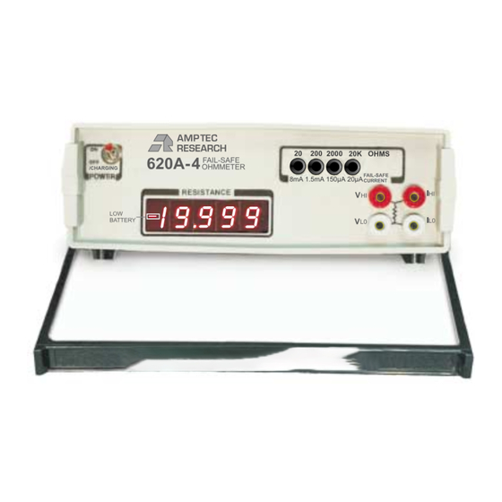
- Page 2 AMPTEC RESEARCH 8mA 1.5mA 150µA 20µA NSN 6625-01-460-1499NM AMPTEC RESEARCH 620A SERIES Failsafe Digital Ohmmeter OPERATION / MAINTENANCE MANUAL Rev. D 10900 Research Blvd., PMB1, Suite # 160 C AUSTIN TX 78759 USA CAGE CODE 1CRL2 Phone 1-800-350-5105 (from the USA), FAX 1-800-430-5440 (from the USA) or (512) 447-7455 website http://www.amptec.com...
- Page 3 (i.e. who to contact). The warranty period for this instrument is 1 year from when it was first shipped . AMPTEC RESEARCH will repair or replace the instrument during the warranty period, provided that it is returned to AMPTEC RESEARCH ( freight prepaid ).
-
Page 4: Table Of Contents
TABLE OF CONTENTS _______________________________________________________________ SECTION A: RECEIVING AND INITIAL INSPECTION Introduction to the AMPTEC 620A 4 Receiving, Unpacking, and Initial Inspection AC Battery Charger- Power Requirements Setup and Use Serial Number and Revision SECTION B: 620A 4 IGNITER TESTER / FAILSAFE OHMMETER SPECIFICATIONS Table B-2. - Page 5 SECTION E: THEORY OF OPERATION General Troubleshooting E-2-1 Localizing the problem E-2-2 Component Replacement Circuit Description Analog-to-Digital Converter E-4-1 Reference Voltage E-4-2 LED Display Ohms-to-DC Converter E-5-1 Constant Current Source E-5-2 Constant Current Circuit Operation Failsafe Design Ultra-Safe Power Supply Scheme SECTION F: ROUTINE MAINTENANCE General Required Test Equipment...
-
Page 6: Receiving, Unpacking, And Initial Inspection
DC current for its DC Office. Retain the shipping resistance measurement. Failsafe Output carton for the carrier's Circuitry proprietary to AMPTEC RESEARCH inspection. ensures that test current levels do not exceed the specified "failsafe current" in a worst-case DO NOT return equipment component failure situation. - Page 7 The 620A uses a 2 ampere Slow Blo (3AG size). Only replace with an identical rated fuse. A spare or replacement battery charger (option “DC”) may be purchased if needed, contact the sales department at AMPTEC RESEARCH.
-
Page 8: Setup And Use
Additional note - Main switch Power “On” . When the 620A Igniter Tester is first turned on, the unit briefly draws more internal power then cuts back to less than 100 mA, after a few seconds. The initial Power “On” battery drain is to heat up the unit’s ovenized zener voltage reference. - Page 9 SECTION B - 620A 4 TESTER SPECIFICATIONS ______________________________________________________________ Table B-2. Specifications Accuracy: (for 1 year @25°C ± 10°C) AMPTEC 620A-4 Igniter Tester... ±0.02% of reading ±0.02% of range (i.e. if you were using a perfect 10.000 Resistance Std.) i0.006 - the high limit for the 20.0 Ohm range is a...
-
Page 10: Section C Optional Items And Accessories
620A Ohmmeter with extra room for test leads, Listed below are the options available for battery charger, 4000ITS Connector use with the AMPTEC 620A Series FailSafe Adapter, single pointed probes and operator Ohmmeters. manual etc. - Page 11 Option 300: 4-Wire Kelvin Lead Set Option 430 4000-ITS Mating Connector Option "300" is a general purpose Kelvin four wire lead set for the 620A series tester. Option 300 is a shielded 48" lead set terminating in ½" opening gold plated copper Kelvin clips.
- Page 12 620A Igniter Tester’s safety. AMPTEC welcomes new requirements. You may contact the sales department at AMPTEC RESEARCH if you need a special probe, adapter, or option not listed in this manual.
-
Page 13: Section D: Operation And Use
_____________________________________________________________ D-1. General Range Switch This section contains complete operating instructions for the AMPTEC 620A Series Failsafe Ohmmeters. A description of the front panel controls, connection instructions, and the theory behind 4-wire resistance measurement is discussed in this section. The AMPTEC 620A input range is selected by depressing the desired button on a gold D-2. -
Page 14: Connections
the front panel. Replace blown fuses with the LEAD RESISTANCE same type and rating only! FAIL-SAFE Charging Jack OHMMETER The battery charging jack is a barrel type and is DC CURRENT located on the 620A rear panel. The center pin LIMITED IGNITER CONSTANT... -
Page 15: Failsafe Operation
All AMPTEC ohmmeters use a high Every 620A Series Failsafe Ohmmeter is impedance voltmeter as part of the thoroughly tested before it leaves the resistance measurement process. This factory. Every resistance range is tested and voltmeter is a highly accurate and stable 4½... -
Page 16: Section E Theory Of Operation
General Since it is not possible to anticipate all failure modes of the 620A, servicing The AMPTEC RESEARCH 620A Fail Safe personnel should become familiar with this Ohmmeter is shown in block diagram form section to gain a complete understanding of in Figure E-1. -
Page 17: Circuit Description
E-3. Circuit Descriptions E-4. Analog-to-Digital Converter The circuit descriptions which follow are The A to D conversion is done with a referenced to Figures E-1, E-2, E-3 and the ICL8068 /ICL71C03 chip set. The ICL8068 schematic diagrams at the back of this takes care of the analog part and the manual. -
Page 19: E-4-1 Reference Voltage
zero crossing point established in Phase I. Detailed Description The time, or number of counts required to do this, is proportional to the input voltage. Analog Section Figures E2 diagrams A thru D shows the equivalent circuit of the analog section in E-4-1. -
Page 20: E-5-2 Constant Current Circuit Operation
The heart of the constant current source is equal to the voltage drops across R213 and the voltage-to-current converter. A R221. At this time the output of IC202 is simplified schematic of this circuit is shown 1.1 volts. The voltage drop across the in Figure E-4 on the next page and described Range Resistor is 1 volt, just as it was when in Section E-5-2 (below). - Page 21 One +5 volt power supply is provided directly by the batteries (for driving the LED displays and digital logic). The ±5VD is used for driving IC8, the low battery detection circuit. The ±15V power supply is generated by IC7 for the digital voltmeter (DVM) chip set (IC1 and IC2).
- Page 22 Figure E-5. LED Display Pin Functions...
-
Page 23: Section F: Routine Maintenance
General This section of the manual contains routine Test Leads: maintenance information regarding the 4-wire lead set AMPTEC RESEARCH Model 620A Fail AMPTEC Option "300" or "301C") Safe Ohmmeters. Calibration should be performed on a regular basis to ensure F-3. -
Page 24: Battery Replacement Instructions
As with all batteries, replacement will eventually be necessary. Batteries may be ordered from AMPTEC RESEARCH as stock #05-10117, quantity: (4). The process of battery replacement is described below: Remove the four feet screws and the bottom cover. - Page 25 SECTION G COMPONENT PARTS LISTS ___________________________________________________ The following parts lists are included in this manual: 620-400 2 pages 620A Main Board Components List (Rev D)
- Page 26 PARTS LIST AMPTEC 620A-400 Revision D ASSEMBLY/PARTS LIST PAGE 1 of 2 PCB Ref STOCK # - # per unit - Description --------------------------- ------- Manuf./ Supplier -----------Alternate R105, R106 01-01004 4.7 , 5% 1/4 W Carbon Film RC07GF470 R218 01-01018 75 , 5% 1/4 W Carbon Film RC07GF750J R14, R21-R24, R227...
- Page 27 PARTS LIST AMPTEC 620A-400 Revision D ASSEMBLY/PARTS LIST PAGE 2 of 2 PCB REF STOCK # # per unit -- - -Description --------------------------- ------- Manuf./ Supplier -----------Alternate 02-50000 0.22uF 10% 50V Polystyrene 02-90006 1.0 µF 50V Polystyrene C202 02-60015 0.022uF, 100V, Mylar, 5% WIMA MKC2-0.022uF (MKC1858.322..014) 02-60017 0.1uF, 250V, Polyester, 5%...
Need help?
Do you have a question about the 620A SERIES and is the answer not in the manual?
Questions and answers