
Subscribe to Our Youtube Channel
Related Manuals for Amptec Research 720A


Summary of Contents for Amptec Research 720A
- Page 1 AMPTEC RESEARCH MODEL 720A OPERATION AND MAINTENANCE MANUAL 13231 Rooster Springs Rd., Austin, TX 78737 amptec.com T: (512) 858-4045 E: info@amptec.com...
-
Page 2: Table Of Contents
720A Operation and Maintenance Manual – Rev S – January 25, 2019 TABLE OF CONTENTS SECTION A: RECEIVING AND INITIAL INSPECTION A-1 Introduction to AMPTEC 720A Digital Micro-Ohmmeter p. 3 A-2 Unpacking and Inspection p. 3 A-3 Setup and Preparation for Use p. -
Page 3: Section A: Receiving And Initial Inspection
20 years. We hope you enjoy working with your 720A meter and encourage you to contact us if you have any questions or comments. Thank you for your business! -
Page 4: Setup And Preparation For Use
AMPTEC meter. A-3 Setup for Preparation and Use The following quick-step guide can be taken to power up and use the AMPTEC 720A meter: 1) The meter may be set up to operate as soon as the power is turned on, which can be accomplished by flipping the “ON/OFF”... -
Page 5: Section B: 720A Specifications
Weight: 4 lbs. B-2 Specifications for AC Input The AC Input power option for the 720A allows the user to plug the meter directly from the AC power outlet to the meter. Meters with this option are supplied with a NEMA 5- 15P US 3 pin power cord that terminates at the meter with a IEC 60320 C-14 connection. -
Page 6: Specifications For Amptec 720A Battery Powered Version (720-Bat)
Unless indicated separately below, all other specifications for the battery powered version of the 720A match those listed in section B-1. The 720-BATT power option for the 720A allows the user to power the meter with rechargeable Nickel–metal hydride (NiMH) batteries. This power option comes with a smart battery charger that has a red LED indicator when the meter is charging, and a green LED indicator when the meter is fully charged. -
Page 7: Section C: 720A Compatible Accessory Items
*Please note that this is not a complete list, as we offer a wide range of accessories. Contact AMPTEC to receive the most current list of 720A compatible accessory items. For pricing information on our packages, accessories, and lead/probe sets, please contact AMPTEC. -
Page 8: Carrying Case
The AMPTEC 720A Digital Micro-Ohmmeter and its accompanying accessories can be carried and stored safely within an OP-100 meter transit case. An OP-100 meter transit case is capable of fitting one 720A meter, two sets of probes/leads, and one AC power cord or battery charger. The below photo demonstrates how a 720A meter and its accessories are stored within a transit case. -
Page 9: Section D: Operation, Features, And Use
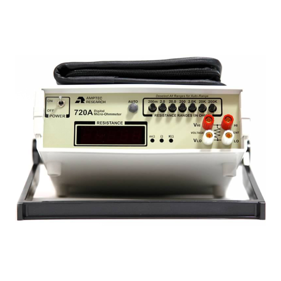
The AMPTEC 720A is a micro-ohmmeter designed to accurately measure low level DC resistance from 200 mΩ to 200 KΩ. The 720A meter may be used immediately after the unit has been turned on and been given a fifteen (15) minute warm up period (temperature range limits permitting). -
Page 10: D-2.1 On/Off Switch
The below photo (Figure 2) shows the details of the front panel of the NSN version of a 720A meter. There are a few key features which differ from the previous photo, and they will be described further in this section. -
Page 11: D-2.3 Display
All resistance measurements made by the unit are presented on this display up to 20,000 counts. The 720A’s display is durable and high quality, meaning it should have a life lasting many years. Should the display become damaged or stop operating properly, it can be replaced at an AMPTEC facility. -
Page 12: D-2.4 Banana Jack Terminals
This button (refer to item 5 within Figure 2 on page 10) is only present in the NSN version of the 720A meter. Pressing this button enables the unit to automatically select its range of measurement, thus activating the unit’s autorange mode. To use this button/feature, first ensure that all other range buttons are fully extended (deselected) and press the AUTO button. -
Page 13: Rear Panel Features
720A meter’s rear panel. The below diagram (Figure 4) shows the details of the NSN version of a 720A rear panel. The key to the right of the rear panel highlights the main features that will be described further in this section:... -
Page 14: D-3.2 Ac Inlet
720A Operation and Maintenance Manual – Rev S – January 25, 2019 new fuse, first ensure that the polarity of the fuse is correct, and then gently push it into the receiver on the inside of the cap. D-3.2 AC Inlet This AC inlet (refer to item 2 within Figure 4 on page 13) acts as a receiver for the AC power cord (P/N 720-AC) that comes with the unit. -
Page 15: D-3.5 Fan, Fan Guard, And Air Intake
This feature (refer to item 6 within Figure 4 on page 13) is only present in the 720-BAT battery powered version of the 720A meter. This DC power jack acts as a receiver for the battery charger (P/N 720-DC) that comes with the unit. It is through this jack that the unit receives power that charges its batteries. -
Page 16: D-5.1 4-Wire Kelvin Information
The OP-300 48” gold-plated Kelvin clip lead set and the OP-403 48” Kelvin mini spear probe set that come standard with the 720A meter both plug directly into the banana jack terminals on the front panel. The spacing of the jacks only allows horizontal connection of the dual banana jack test leads to prevent misconnection. -
Page 17: Detailed Use Description
If operating a 720A meter in a more extreme climate, a warm up period of thirty (30) minutes is ideal. This warm up period allows the unit to adjust to the room’s ambient temperature and enables it to accurately take/display measurements. - Page 18 If your 720A meter does not have an autorange function and the resistance value is unknown, start on the 200 KΩ...
-
Page 19: Detailed Use Description For Rs-232C Function
Note: Readings taken through the RS-232C communication interface may be from either the front or rear panel. D-7.1 RS-232C Commands and Data Format This section details the commands necessary to communicate with your 720A meter via its RS-232C connection. The RS-232C communication protocol for the 720A is listed below:... - Page 20 720A Operation and Maintenance Manual – Rev S – January 25, 2019 r0 Deselects all ranges. r1 Selects the 200 mΩ range. r2 Selects the 2 Ω range. r3 Selects the 20 Ω range. r4 Selects the 200 Ω range.
-
Page 21: Section E: Maintenance, Repair, And Calibration
720A Operation and Maintenance Manual – Rev S – January 25, 2019 SECTION E: MAINTENANCE, REPAIR, AND CALIBRATION E-1 General Maintenance, Repair, and Calibration Information The AMPTEC 720A meter was designed using high quality, strong, and reliable components both internally and externally. However, as with all precise instrumentation, components may fail after prolonged periods of use. -
Page 22: Basic Troubleshooting
720A Operation and Maintenance Manual – Rev S – January 25, 2019 E-3 Basic Troubleshooting The following section will assist you in diagnosing simple problems with your 720A meter. While there are a few common errors that can be resolved by the end user, it is often recommended that you send your unit back to AMPTEC’s facility for further... -
Page 23: E-3.1 Battery Replacement
AMPTEC for assistance. E-3.1 Battery Replacement Battery replacement of your 720A meter is strongly discouraged and should only be completed by qualified and authorized individuals. It is recommended that in the event of battery failure the unit is sent back to AMPTEC, where we can safely replace the batteries for you (for more information on how to send your product in for this service, see section E-2). -
Page 24: E-3.2 Current Source Diagnostic Test Routine
1 year, but the unit may be calibrated more often if desired. When calibrating the 720A meter, the unit should warm up for at least 30 minutes prior to calibration. If battery powered, the unit should be fully charged. If possible, the unit should ideally be calibrated in a room with optimal ambient temperature (21º... -
Page 25: E-4.1 Equipment Required To Complete 720A Calibration Procedure
720A Operation and Maintenance Manual – Rev S – January 25, 2019 All calibration adjustment points are accessed by removing the screws within the feet on the bottom of the unit, then lifting off the top lid. Note that if your unit has an RS-232C interface you will see two PC boards when you remove the top lid. -
Page 26: E-4.2 Trimmer Potentiometer Adjustment Locations
720A Operation and Maintenance Manual – Rev S – January 25, 2019 Precision Standard Resistors Continued: • One 100 KΩ resistance standard at ± 0.005% or better accuracy Other Equipment: • One trimmer potentiometer adjustment tool • One AMPTEC OP-300 48” gold plated Kelvin clip lead set •... -
Page 27: E-4.3 Calibration Procedure Adjustments
E-4.3 Calibration Procedure Adjustments This section contains information on the specific adjustments necessary to calibrate a 720A meter. Ensure that you have first followed the instructions detailed in the calibration procedure overview in section X before completing any of the internal adjustments below.
Need help?
Do you have a question about the 720A and is the answer not in the manual?
Questions and answers