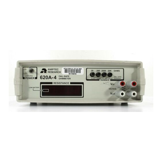
Amptec Research 620A-4 Operation & Maintenance Manual
Digital failsafe ohmmeter
Hide thumbs
Also See for 620A-4:
- Operation and maintenance manual (24 pages) ,
- Operation & maintenance manual (25 pages)

Related Manuals for Amptec Research 620A-4


Summary of Contents for Amptec Research 620A-4
- Page 1 MODEL 620A-4 OPERATION/ MAINTENANCE MANUAL Phone +1 (512) 858-4045 // Fax +1 (512) 858-4340 www.amptec.com // info@amptec.com REV. H...
-
Page 2: Table Of Contents
TABLE OF CONTENTS SECTION A: RECEIVING AND INITIAL INSPECTION Introduction to the AMPTEC 620A-4 Receiving, Unpacking, and Initial Inspection AC Battery Charger- Power Requirements Setup and Use Serial Number, Revision and Safety Board Approvals 620A-4 SECTION B: 620A 4 IGNITER TESTER / FAILSAFE OHMMETER SPECIFICATIONS Table B-2. - Page 3 SECTION E: THEORY OF OPERATION General Troubleshooting E-2-1 Localizing the problem E-2-2 Component Replacement Circuit Description Analog-to-Digital Converter E-4-1 Reference Voltage E-4-2 LED Display Ohms-to-DC Converter E-5-1 Constant Current Source E-5-2 Constant Current Circuit Operation Failsafe Design Ultra-Safe Power Supply Scheme Relay Board General Operation SECTION F: ROUTINE MAINTENANCE General...
-
Page 4: Introduction To The Amptec 620A-4
(EEDs) or “current sensitive” blasting devices. Approvals from various Safety Should the AMPTEC shipping box appear Boards include, the U.S. Air Force ( 620A-4) for damaged upon arrival, request that the carrier's use on Non-Nuclear munitions provided the agent (i.e. - Page 5 “Power On” time. An “Overnight” charge usually restores the 620A-4 to a “Fully Charged” ready to use state. If you turn on the 620A-4, and the display does not come on, it may indicate the batteries need charging.
- Page 6 Additional note - Main switch Power “O . n” When This product is also the 620A-4 Igniter Tester is first turned on, the certified for Use in Explosive Fuel Air Mixtures per unit briefly draws more internal power then cuts Mil Standard 810 Method 511.
- Page 7 (for 1 year @25°C ± 10°C) 20 ohm through 20Kohm ranges ....... ±0.02% of reading ±0.02% of range (i.e if you a using a 10.000 ohm Resistance Std. - the high limit for the 620A-4 is a ohm reading and the low limit is...
-
Page 8: Section C Optional Items And Accessories
Option "DC" is an AC/DC converter that converts equipment rack. 115VAC line voltage to 6VDC at 300mA. One charger is provided as a standard accessory with every 620A-4. C-2. Test Lead Sets and Probes A 220 VAC 50 Hz powered Battery Charger adapter is also available. - Page 9 4 NSN 6625-01-460-1499NM package. The “OP430” has terminated in ½" opening gold-plated Kelvin clips. the AMPTEC 620A-4 Ohmmeter act as a 2-wire The option "300" can clip easily to wires, pins, and ohmmeter from the OP430 connector out to the resistance medium size (up to ½"...
-
Page 10: Section D: Operation And Use
Also note that a resistance range should be selected after powering up the 620A-4 to place it in an operational mode. After turn "ON", a range should be selected. If the resistance being measured (including "Open Circuit/... - Page 11 AMPTEC 620A-4 REAR PANEL configured with Option "232", "247" (not part of NSN 6625-01-460-1499NM package) RS232C Interface FUSE - 2 ampere revision 2.0 3AG FAST BLO OP247 Adapter AMPTEC MADE IN USA RESEARCH www.amptec.com MODEL NUMBER 620A4 SERIAL NUMBER 620A4-1278...
-
Page 12: Connections
LEAD RESISTANCE Charging Jack FAIL-SAFE The battery charging jack is a barrel type and is OHMMETER located on the 620A-4 rear panel. The center pin of the connector is positive. The charging LIMITED IGNITER requirements of the internal battery pack are... -
Page 13: Failsafe Operation
The typical fail-safe current for each range is indicated under the corresponding range switch on the 620A-4 front panel. Please refer to section 5- 6 for a technical description of the failsafe circuitry. - Page 14 Replacing the AMPTEC 620A-4 Handles Rotating the AMPTEC 620A-4 Instrument Case and Handle Position The AMPTEC 620A-4 handle access screws are The AMPTEC 620A-4 handles position can be located behind the black circular end caps (see easily adjusted or rotated with the simple points A and B in the diagram below) at the joint maneuver described below.
-
Page 15: General
E-2. Troubleshooting the first things that should be tested. Since the 620A-4 Tester is used to test potential As it is not possible to anticipate all failure deadly explosive force detonators and warheads modes of the 620A-4 series igniter tester, of missiles etc., personnel that are not qualified... - Page 16 - i.e. connect to an earth ground to avoid a static discharge to a static sensitive component. Handle all 620A-4 internal components as if they are static sensitive if you are not sure.
-
Page 17: Circuit Description
CURRENT SOURCE MULTIPLEXER INPUT INTEG BUFFER SWITCH COUNTERS CONTROL LOGIC COMPARATOR ZERO CROSSING DETECTOR MODEL 620A-4 OHMMETER BLOCK DIAGRAM COUNTS PHASE III PHASE I PHASE II I0.00 I I0.000 20.00 I 4 ½ DIGIT ZERO CROSSING POLARITY OCCURS DETECTED ZERO CROSSING... - Page 18 R INT C INT BUFFER INTEGRATOR COMPARATOR 1 µF ZERO CROSSING DETECTOR C REF C AZ C STRAY V IN FIGURE E-2A. PHASE l AUTO-ZERO R INT C INT BUFFER INTEGRATOR COMPARATOR 1 µF ZERO CROSSING DETECTOR C REF C AZ C STRAY V IN POLARITY...
-
Page 19: E-4-1 Reference Voltage
3 closes a loop around the integrator and BCD data is converted to seven segment format comparator, the purpose of which is to charge the by IC4. When the 620A-4 electronics are in Auto-Zero capacitor until the integrator output open circuit or over-range mode the display does not change with time. -
Page 20: E-5-2 Constant Current Circuit Operation
R212 and R222 are equal to the drops across R213 and R221. For these The AMPTEC 620A-4 Tester is powered by a voltage drops to be equal, the output of IC202 rechargeable internal battery pack and cannot be must be at +1 volt. -
Page 21: Ultra-Safe Power Supply Scheme
IC7 for the digital voltmeter (DVM) chip set (IC1 and IC2). For the 620A-4 Tester the normal or typical operating current level is less than 5 mA, and The ±5 VA is developed by one DC to DC <8mA on most 20 ohm range versions as a... -
Page 22: Relay Board General Operation
For products such as the ruggedized water-proof version AMPTEC 620A-4R Igniter Tester and remote controlled versions via the RS232C Interface option, the internal 620A-4(R) PCB labeled “620-relay board” replaces the range switch S1 on the main board. IC-1 is a ribbon... -
Page 23: Section F: Routine Maintenance
15 minutes The AMPTEC 620A-4 is a four wire Kelvin before beginning the procedure. The ohmmeter. The 620A-4 must be calibrated adjustments are accessed by removing the... -
Page 24: Battery Replacement Instructions
F-4. Battery Replacement Instructions The rechargeable Nicad batteries (D cell 5.0 AHr each) used in the 620A-4 are very durable and should provide years of trouble- free operation. As with all batteries, replacement will eventually be necessary. Batteries may be ordered from AMPTEC Option “620-BAT”...
Need help?
Do you have a question about the 620A-4 and is the answer not in the manual?
Questions and answers