Advertisement
Quick Links
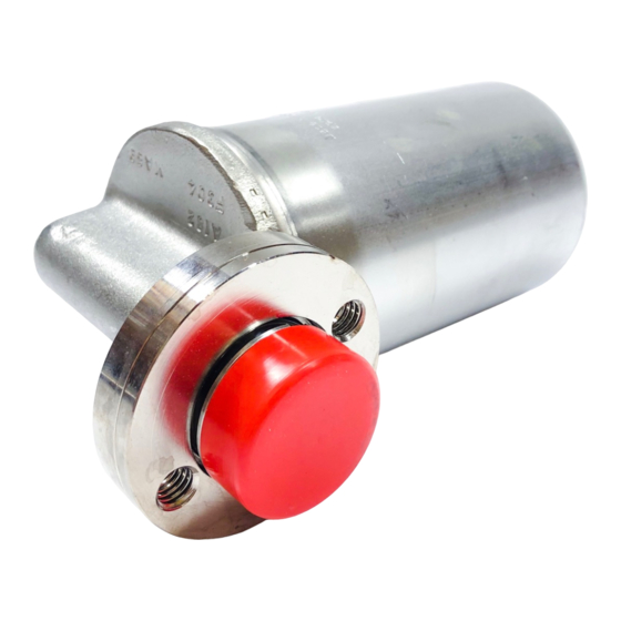
UIB30 and UIB30H Sealed Inverted Bucket Steam Trap
Model
Trap
Construction
Connector
Sizes
Connector
Connections
Connector
Straight or strainer type (left or right hand)
Stainless steel or cast steel
Construction
Connector
SW connections to ANSI B16.11
Options
USTSII trap station
The trap contains an inverted bucket mechanism which responds to the
difference in density between steam and condensate. The discharge action
is cyclic. Condensate and non-condensibles are discharged close to steam
temperature. The UIB is designed to maintain the bucket in the proper plane
by means of a swivel connector. The trap is easily replaced without disturbing
the piping connections.
Limiting Operating Conditions
Max. Operating Pressure
(PMO)
Envelope Pressure Range
0
145
290
400
Steam
300
saturation
curve
200
100
0
0
10
20
The product must not be used in this region.
*PMO Maximum operating pressure recommended.
A - A Flanged ANSI 300, screwed and socket weld
C - C Flanged ANSI 150
Capacities
Differential Pressure bar
1
2
1,000
900
800
700
600
500
400
300
200
100
8 10
20
30 40
Differential Pressure, psi
Local regulation may restrict the use of this product below the conditions quoted. Limiting conditions refer to standard connections only.
In the interests of development and improvement of the product, we reserve the right to change the specification.
UIB 30
466
(for use with Universal Connectors)
UIB30, UIB30H
Stainless Steel
½", ¾", 1"
NPT, SW
Carbon steel
UIB30/8
58 psig (4 barg)
UIB30H/10 72 psig (5 barg)
123 psig (8.5 barg)
UIB30/7 UIB30H/8
UIB30/6
174 psig (12 barg)
UIB30/5 UIB30H/6
290 psig (20 barg)
UIB30/4 UIB30H/5
435 psig (30 barg)
Pressure psig
435
580
725
752
A
572
392
206
A
32
30
40
50
Pressure barg
3
4
5
10
20
58
60
290
300
80
100
125
175
200
(Connector of choice sold separately)
See TI-2-519-US
12
14
7
9
Typical Applications
Steam tracing, steam main drip stations, laundry equipment,
industrial dryers, and storage tanks.
Construction Materials
No. Part
30
1
Cover
400
2
Body
3
Bucket
300
4
Valve Guide Plate
5
Valve Seat
6
Valve
200
7
Valve Lever
8
Internal Tube
9
Guide
10
Flange
12
Connector Screw
100
13
Inlet Gasket
14
Outer Gasket
50
Note: The body/cover weld joint is to BS4870 (1981) and complies with ASME section IX.
400
Material
Stainless Steel
ASTM A240 Gr 304
Stainless Steel
ASTM A 351 CF8
Stainless Steel
BS 1449 321 S 12
Stainless Steel
BS 1449 321 S 12
Stainless Steel
AISI 440B
Stainless Steel
AISI 440B
Stainless Steel
BS 1449 321 S 12
Stainless Steel
BS 3605 304 S 14
Stainless Steel
BS 1449 304 S 16
Alloy Steel
ASTM A322 Gr 4130
Steel
ASTM A 193 B7
Stainless Steel
AISI 304 Strip
& Filler (Asbestos Free)
Stainless Steel
AISI 304 Strip
& Filler (Asbestos Free)
TI-2-412-US
10
13
2
5
4
6
3
1
8
1.18
Advertisement

Subscribe to Our Youtube Channel
Related Manuals for Spirax Sarco UIB30


Summary of Contents for Spirax Sarco UIB30
- Page 1 UIB30 and UIB30H Sealed Inverted Bucket Steam Trap (for use with Universal Connectors) Model UIB30, UIB30H Trap (Connector of choice sold separately) Stainless Steel Construction See TI-2-519-US Connector ½”, ¾”, 1” Sizes Connector NPT, SW Connections Connector Straight or strainer type (left or right hand)
- Page 2 UIB30 and UIB30H Sealed Inverted Bucket Steam Trap (for use with Universal Connectors) Dimensions (nominal) in inches and millimeters Size Weight (UIB30) (UB30H) 1/2" 4.8 lb 2.19kg 3/4" 5.5 lb 2.22kg 1" 5.2 lb 2.38 kg Sample Specification Spare Parts...
Need help?
Do you have a question about the UIB30 and is the answer not in the manual?
Questions and answers