
Related Manuals for NSD VARICAM VS-5F Series


Summary of Contents for NSD VARICAM VS-5F Series
- Page 1 ZEF004640911 Electronic Rotary Cam Switch VS-5F Series (For SP1) Specifications and Instruction Manual VARICAM VS-5F VS-5F-1 VS-5FD VS-5FD-1 VS-5FX VS-5FX-1 ABSOCODER VRE-P062 VRE-P028...
- Page 3 CONTENTS INTRODUCTION ....................................... i HOW TO READ THIS MANUAL ................................i COPYRIGHT ......................................i GENERAL SAFETY RULES................................... ii REVISION HISTORY ....................................v SUMMARY Describes about summary and model selection. 1. SUMMARY ......................................2 1-1. Summary ......................................2 1-2. Features ......................................3 1-3.
- Page 4 CONTENTS The operation is divided into a basic and applied function, and explains about usage. OPERATION 7. HOW TO USE BASIC FUNCTION ..............................42 7-1. Nomenclature and Function of the Panel Side ......................... 42 7-2. Operation Flow ..................................... 44 7-3. Procedure before the Operation..............................45 7-4.
- Page 5 CONTENTS Describes about daily inspections and countermeasures for errors. MAINTENANCE 11. INSPECTIONS ....................................100 12. TROUBLE SHOOTING ................................101 12-1. Error Displays and Countermeasures ..........................101 12-2. Procedure Contents after Replacing ............................ 102 12-3. Initialization Operation ................................103 Attaches the following contents APPENDIX APPENDIX 1.
-
Page 6: How To Read This Manual
INTRODUCTION Thank you very much for purchasing our product. Before operating this product, be sure to carefully read this manual so that you may fully understand the product, safety instructions and precautions. - Please submit this manual to the operators actually involved in operation. - Please keep this manual in a handy place. -
Page 7: General Safety Rules
This product is not designed to be used under any situation affecting human life. When you are considering using this product for special purposes such as medical equipment, aerospace equipment, nuclear power control systems, traffic systems, and etc., please consult with NSD. Compliance with KC mark (Korea Certification Mark): This product is a Class A device (Broadcast communication device for industrial environment). - Page 8 - Do not store VARICAM in a place exposed to water, or toxic gas and liquid. - Be sure to store VARICAM in designed temperature and humidity range, and do not exposed to direct sunlight. - Be sure to consult with NSD when VARICAM is stored for long periods. 3. Transport CAUTION - Do not hold the cable or shaft of ABSOCODER during transport;...
-
Page 9: Maintenance And Inspection
6. Operation CAUTION - Do not change the VARICAM's function switch settings during the operation; otherwise, it will cause injury. - Do not approach the machine after instantaneous power failure has been recovered. Doing so may result in injury if the machine starts abruptly - Be sure to check that the power supply specifications are correct;... -
Page 10: Revision History
REVISION HISTORY The Document No. appears at the upper right of this manual's cover page. Document No. Date Revision Description ZEF004640900 29, Feb., 2008 1st Edition Japanese document: ZEF004640201 ZEF004640901 7, Jul., 2008 2nd Edition Japanese document: ZEF004640202 ZEF004640902 22, May, 2009 3rd Edition Japanese document: ZEF004640203 ZEF004640903... - Page 11 SUMMARY Describes about summary and model selection. 1. SUMMARY 2. MODEL SELECTION WHEN ORDERING...
- Page 12 SUMMARY 1. SUMMARY 1. SUMMARY 1-1. Summary A mechanical type cam switch has been used in order to detect a rotation angle in automatic machinery such as packing, printing, press, and assembly machines. However, difficult angular adjustment and switch replacement procedures have long been onerous tasks.
- Page 13 SUMMARY 1. SUMMARY 1-2. Features (1) High reliability An absolute position detection format ensures accurate position detection even if a power interruption or unexpected noise condition occurs. An origin returning operation is not required. (2) Superior durability ABSOCODER is not used electronic parts except coils and resistance, and it features a no-contact construction excepting bearing.
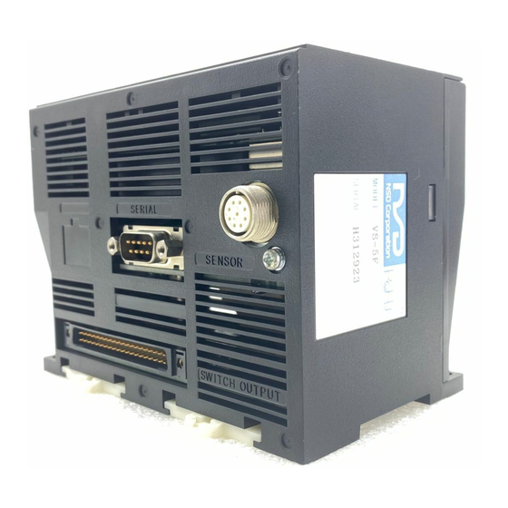
- Page 14 SUMMARY 1. SUMMARY 1-3. Nomenclature ●Front side ●Right side Power supply terminal block (M3) Display part S P 1 Operation part Nameplate ●Bottom side Serial communication connector Connects to the personal computer, etc… Sensor connector Connects with ABSOCODER. BCD output connector Connects to the program No.
- Page 15 SUMMARY 1. SUMMARY 1-4. Function Describes about VS-5F Series functions. Function Description The switch output works the same function as the mechanical format cam switch that is configured with a cam disk and limit switch. ON/OFF settings are designated at the VARICAM, and switch output ON/OFF operations occur according to the rotation angle of ABSOCODER.
- Page 16 SUMMARY 1. SUMMARY Function Description The primary feature of VARICAM can set and change the switch output easily. However, there are switch outputs which are not wanted to set and change easily. The protected switch function can solve these kinds of problems. The protected switch function can be used for switch Nos.
- Page 17 SUMMARY 1. SUMMARY Function Description Outputs the pulse signal which is equally divided single rotation of the machine (ABOSOCODER). This function is used when connecting the parallel type external display unit (NDP). The pulse number is selectable from 60, 180, or 360 per rotation by the parameter. If this function is using, “Motion detection switch output function”...
- Page 18 SUMMARY 1. SUMMARY Function Description The current position value output function outputs rotation positions (angles) of the machine by BCD codes or gray code (720-division). The speed output function outputs rotation speeds of the machine by binary codes. The current position value output and speed output function are sharing an output pin, so it is necessary to choose either one.
- Page 19 VS-5F Series supports existing communication protocol of VS-5E Series. For more details regarding the serial communication, please contact your NSD representative. This function is applied to all models that are written "SP1" in the lower right portion of the front panel.
- Page 20 SUMMARY 2. MODEL SELECTION WHEN ORDERING 2. MODEL SELECTION WHEN ORDERING Following figure is indicated connecttion configuration of VARICAM “VS-5F Series”. Before ordering, please refer to the connection configuration and model list. Please prepare equipments by the customer except from ① to ⑪ in the connection configuration. ●Connection configuration ①...
- Page 21 SUMMARY 2. MODEL SELECTION WHEN ORDERING ●Model list ◆VARICAM Model Description VS-5F 1 program, 24 points output VS-5FD 100VAC model 8 programs, 24 points output VS-5FX 16 programs, 40 points output or 32 programs, 24 points output ① VS-5F-1 24VDC model 1 program, 24 points output VS-5FD-1 8 programs, 24 points output...
- Page 22 SUMMARY 2. MODEL SELECTION WHEN ORDERING -MEMO-...
-
Page 23: Specification
SPECIFICATION Describes about specifications and outer dimensions. 3. SPECIFICATIONS 4. OUTER DIMENSIONS... -
Page 24: General Specification
SPECIFICATION 3. SPECIFICATIONS 3. SPECIFICATIONS 3-1. VARICAM Specifications 3-1-1. General Specification Items Specifications Model VS-5F, VS-5FD, VS-5FX VS-5F-1, VS-5FD-1, VS-5FX-1 Power supply 100VAC 50/60Hz 24VDC voltage Permissible power 85 to 132VAC 21.6 to 30VDC voltage range Power consumption 20VA or less 10W or less 20 MΩ... -
Page 25: Performance Specification
SPECIFICATION 3. SPECIFICATIONS 3-1-2. Performance Specification Items Specifications Model VS-5F, VS-5F-1 VS-5FD, VS-5FD-1 VS-5FX, VS-5FX-1 Number of programs 8 (0 to 7) 16 (0 to 15) 32 (0 to 31) Number of switches Number of Multi-dogs 10 times for each switch output (0 to 9) Position detection format Absolute position detection Number of detection axes... - Page 26 SPECIFICATION 3. SPECIFICATIONS 3-1-3. I/O Specification Items Specifications Model VS-5F, VS-5F-1 VS-5FD, VS-5FD-1 VS-5FX, VS-5FX-1 -Error cancel 1 point -Program No. 3 points -Program No. 4 points -Program No. 5 points -Switch output enabling 1 point -Current position HOLD 1 point -Current position HOLD 1 point -Current position HOLD...
- Page 27 Full duplex, start stop synchronization Half duplex, start stop synchronization Transmission speed 2400,4800,9600,19200,38400,57600 bps Communication signal TXD, RXD, RTS, CTS, SG DATA+, DATA-, SG Connector format 9-pin connector (D-sub male) For more details about the serial communication, please contact your NSD representative.
- Page 28 SPECIFICATION 3. SPECIFICATIONS 3-2. ABSOCODER Specification Items Specifications Sensor model VRE-P028 VRE-P062 Total number of turns Mass 0.25 kg 1.3 kg Linearity error 1.5°Max. 1°Max. 9.3×10 kg・m 6.4×10 kg・m Moment of inertia GD /4(J) (9.5×10 kgf・cm・s (6.5×10 kgf・cm・s 1.5×10 N・m or less 4.9×10 N・m or less Starting torque...
-
Page 29: Outer Dimensions
SPECIFICATION 4. OUTER DIMENSIONS 4. OUTER DIMENSIONS 4-1. VARICAM Outer Dimensions ●VS-5F-1 (VS-5F is same size as VS-5F-1.) Units: mm Mounting hole S P 1 ●VS-5FD-1 (VS-5FD is same size as VS-5FD-1.) Units: mm Mounting hole S P 1... - Page 30 SPECIFICATION 4. OUTER DIMENSIONS ●VS-5FX-1 (VS-5FX is same size as VS-5FX-1.) Units: mm Mounting hole S P 1 ●VS-K-F (Panel-mounting fixture) VS-K-F can be used with all VS-5F series. S P 1 Blank Terminal block mounting position Panel cut dimensions The terminal block for relay of the power supply is able to mount on the back or side.
- Page 31 SPECIFICATION 4. OUTER DIMENSIONS 4-2. ABSOCODER Outer Dimensions Units: mm ●VRE-P062SAC ●VRE-P062SBC ●SH-01 (Reinforced servo-mount fixture for VRE-P062SAC / SBC) Option (2 pieces / 1set)
- Page 32 SPECIFICATION 4. OUTER DIMENSIONS Units: mm ●VRE-P062FAC ●VRE-P062FBC ●RB-01 (L type flange-mount fixture) Option L type flange-mount fixture is for VRE-P062. Following combinations are able to use with. - VRE-P062SAC/SBC + SH-01 - VRE-P062FAC/FBC...
- Page 33 SPECIFICATION 4. OUTER DIMENSIONS Units: mm ●VRE-P028SAC...
- Page 34 SPECIFICATION 4. OUTER DIMENSIONS 4-3. Extension Sensor Cable Outer Dimensions ●3P-S-0102-[L] or 3P-RBT-0102-[L] Units: mm NOTE: [L] is given in terms of meter. 4-4. External Cable Outer Dimensions Units: mm ●VS-C05-[L] NOTE: [L] is given in terms of meter.
- Page 35 INTRODUCTORY Describes about packing contents, mounting methods, and wiring methods. 5. INSTALLATION 6. WIRING and CONNECTION...
-
Page 36: Installation
INTRODUCTORY 5. INSTALLATION 5. INSTALLATION The handling procedures from the point of delivery to system installation are described in this chapter. 5-1. Checking the Contents of the Shipping Case Open the packing case, and verify that all items are present. (1) VARICAM ①... - Page 37 INTRODUCTORY 5. INSTALLATION 5-2. Installation Conditions and Precautions The VARICAM and ABSOCODER installation procedures and precautions are described. Refer to “4. OUTER DIMENSIONS” for mounting dimensions. 5-2-1. VARICAM Installation Conditions and Precautions When installing VARICAM, the following conditions and precautions should be observed. - Installation site (1) Avoid sites where the unit is exposed to direct sunlight.
- Page 38 INTRODUCTORY 5. INSTALLATION 5-2-2. ABSOCODER Installation Conditions and Precautions The installation conditions and precautions for ABSOCODER are described in this chapter. - Handling of Turn-type ABSOCODER Item Explanation 1) Main unit 2) Cable - Mounting of Turn-type ABSOCODER Item Explanation Precaution 1) Mounting For details regarding mounting dimensions, refer to each...
- Page 39 INTRODUCTORY 5. INSTALLATION - Mounting of Turn-type ABSOCODER Item Explanation Precaution A “direct-link” format will 1) Coupling of machine result in shaft fatigue shaft and sensor and / or breakage after shaft long periods. Therefore, be sure to use a coupling device to link the shafts.
- Page 40 INTRODUCTORY 5. INSTALLATION - Coupling of Turn-type ABSOCODER Item Explanation Precaution 1) Coupling device The selection of a selection precaution larger coupling than necessary will increase the shaft load which is caused by the mounting error amount. Excessive force applied to the shaft can deform the coupling and reduce durability.
-
Page 41: Wiring And Connection
INTRODUCTORY 6. WIRING and CONNECTION 6. WIRING and CONNECTION 6-1. Power Supply Connection Describes about the power supply connection. (1) Isolation transformer In the case of using VARICAM with 100VAC model (VS-5F, VS-5FD, VS-5FX) Connect the isolation transformer if the noise influences VARICAM. 100 VAC 1:1 Isolation... - Page 42 INTRODUCTORY 6. WIRING and CONNECTION 6-2. Connection between VARICAM and ABSOCODER Describes about the connection of VARICAM and ABSOCODER. ●Cable connection ABSOCODER is equipped with a 2-meter cable. If a length is required, the dedicated extension sensor cable of special must be used. The maximum extensible length is 100m. ABSOCODER VARICAM Extension sensor cable...
-
Page 43: Connector Connections
INTRODUCTORY 6. WIRING and CONNECTION 6-3. Connector Connections Describes about the connector connection. 6-3-1. Connector Names and Functions Serial communication connector Connects to the personal computer, etc… Sensor connector Connects to ABSOCODER. BCD output connector Connects to the program No. input and current position value output, etc…... - Page 44 INTRODUCTORY 6. WIRING and CONNECTION 6-3-3. I/O Signal Condition in the Each Mode Indicates connector's I/O signal condition in each mode. Mode RUN mode Switch setting mode Parameter setting mode Signal name (RUN) (SET) (PRM) Depending on the parameter No. 94 setting, Switch determines whether output is OFF or HOLD.
- Page 45 INTRODUCTORY 6. WIRING and CONNECTION 6-3-4. I/O Circuit (1) Output circuit ① Switch output (Arbitrary pulse), program No., ② Current position value (speed), latch pulse system ready, timing pulse (Motion detection switch) 24VDC 24VDC (2) Input circuit Program No., current position HOLD (external origin set), error cancel, switch output enabling...
- Page 46 INTRODUCTORY 6. WIRING and CONNECTION 6-3-5. I/O Connector Pin Arrangement (1) VS-5F, VS-5FD, VS-5F-1, VS-5FD-1 ① Switch output connector (SWITCH OUTPUT) The pin arrangements of switch output connectors are the same both VS-5F(-1) and VS-5FD(-1). [ Connector model: FCN361J040-AU / FCN-360C040-E (FUJITSU COMPONENT LIMITED) ] Signal name Pin No.
- Page 47 INTRODUCTORY 6. WIRING and CONNECTION (2) VS-5FX, VS-5FX-1 ●When using a 16-program, 40-switch output format ① Switch output connector (SWITCH OUTPUT) [ Connector model: FCN361J040-AU / FCN-360C040-E (FUJITSU COMPONENT LIMITED) ] Signal name Pin No. Pin No. Signal name Switch output 1 Switch output 17 Switch output 2 Switch output 18...
- Page 48 INTRODUCTORY 6. WIRING and CONNECTION ●When using a 32-program, 24-switch output format ① Switch output connector (SWITCH OUTPUT) [ Connector model: FCN361J040-AU / FCN-360C040-E (FUJITSU COMPONENT LIMITED) ] Pin No. Signal name Pin No. Signal name Switch output 1 Switch output 17 Switch output 2 Switch output 18 Switch output 3...
- Page 49 DATA+ - Mounting Shield must be connected. SHIELD Cable shield screw Connector on the VARICAM side Model : DELC-J9PAF-13L6E (9-pin male) Manufacturer : Japan Aviation Electronics Industry, Ltd. For more details about the serial communication, please contact your NSD representative.
- Page 50 INTRODUCTORY 6. WIRING and CONNECTION -MEMO-...
-
Page 51: Operation
OPERATION The operation is divided into a basic and applied function, and explains about usage. 7. HOW TO USE BASIC FUNCTION 8. HOW TO USE APPLIED FUNCTIONS (PARAMETER) 9. HOW TO USE APPLIED FUNCTIONS (SWITCH OUTPUT) 10. HOW TO USE APPLIED FUNCTIONS (OPERATION MODE) - Page 52 OPERATION 7. HOW TO USE BASIC FUNCTION 7. HOW TO USE BASIC FUNCTION VARICAM can operate easily with operation instruction of this chapter. 7-1. Nomenclature and Function of the Panel Side Describes nomenclatures and functions of the panel side ●LED indicator ①...
- Page 53 OPERATION 7. HOW TO USE BASIC FUNCTION ●Indicators Name Descriptions Indicates selecting mode. Mode indicator RUN LED is ON: The operation (RUN) mode is selected. ① SET LED is ON: The switch setting (SET) mode is selected. RUN, SET, PRM PRM LED is ON: The parameter setting (PRM) mode is selected.
-
Page 54: Operation Flow
OPERATION 7. HOW TO USE BASIC FUNCTION 7-2. Operation Flow An operation flowchart is shown below. Mode selection Parameter setting Operation (RUN) Switch setting (PRM) (SET) Blink Blink Blink Press long Press long Press long Operation (RUN) mode Parameter setting (PRM) Switch setting (SET) mode mode PRM LED ON... - Page 55 OPERATION 7. HOW TO USE BASIC FUNCTION 7-3. Procedure before the Operation Describes the procedure until operation. Start Power supply ON ----- Refer to “7-4. Turn ON the Power Supply”. ----- Refer to “7-5. Sets the Parameter “. Set the parameter Set the switch output ----- Refer to “7-6.
- Page 56 OPERATION 7. HOW TO USE BASIC FUNCTION 7-4. Turns ON the Power Supply The VS-5F Series doesn’t have any power supply switch; therefore, use external switch for turning ON / OFF the power supply. Before turning ON the power supply, be sure that the wiring is correct and the screws of terminal block are securely tightened.
- Page 57 OPERATION 7. HOW TO USE BASIC FUNCTION 7-5. Sets the Parameter VARICAM can operate easily only setting next parameter. The numeric value “( )” indicates the parameter number. Start For more parameter details, refer to the parameter list on next page. Move the machine to the reference position.
- Page 58 OPERATION 7. HOW TO USE BASIC FUNCTION ●Parameter List Name Description Setting range Initial value Displays “00” at first when selecting the Initial display parameter setting (PRM) mode. This function must be designated at first 0: 16-program, 40-switch VS-5FX output when using VS-5FX(-1) after delivery.
- Page 59 OPERATION 7. HOW TO USE BASIC FUNCTION 7-5-2. Sets the Output Specifications of VS-5FX This setting is only for using VS-5FX-1. Designates the combination of program and switch output numbers. - Sets the parameter by the following procedures. ① Selects parameter No.02. Displays numbers of Selects “02”...
- Page 60 OPERATION 7. HOW TO USE BASIC FUNCTION 7-5-3. Sets the Rotation Direction of ABSOCODER This setting is designated the rotation direction of ABSOCODER’s shaft in which the current position value increase. Checking the number that is displayed here is not necessary. - Sets the parameter by the following procedures.
- Page 61 OPERATION 7. HOW TO USE BASIC FUNCTION 7-5-4. Sets the Origin Point This setting is for matching the values of the machine position and current position on VARICAM's display when the machine position is on the origin point (0 degree). Sets the “origin point setting”...
- Page 62 OPERATION 7. HOW TO USE BASIC FUNCTION 7-5-5. Sets the Current Position Value If the machine cannot move to origin point position, this setting will be used. The machine position value should be input by the key. Match the current position value on VARICAM’s display and the machine position.
- Page 63 OPERATION 7. HOW TO USE BASIC FUNCTION 7-6. Sets the Switch Outputs 7-6-1. Selects the Switch Setting (SET) Mode LED ON/OFF state : ON : OFF : BLINK Keeps to press [MODE] key more than 1 second. POSITION and MODE display areas are blinking, and changes to mode selection screen.
- Page 64 OPERATION 7. HOW TO USE BASIC FUNCTION 7-6-2. Sets the Switch Outputs Explains the switch output setting procedure below, and it explains using contents of the setting example. Setting example Program No. : 1 Switch No. : 1 ON angle 125.5°...
- Page 65 OPERATION 7. HOW TO USE BASIC FUNCTION ⑤ Turns ON the OFF LED. *1 Presses [ON / OFF] key in order to designate Displays by 0.5°units Decimal point is ON : 0.5° the OFF angle. The OFF LED turns ON. OFF LED Decimal point is OFF : 0.0°...
- Page 66 OPERATION 7. HOW TO USE BASIC FUNCTION 7-7. Operation The operation procedure is following: [1] Selects the switch setting (SET) mode. [2] Selects the program number to be operated. [3] Selects the operation (RUN) mode. [4] Operation (RUN) VS-5F(-1) doesn’t have any program function, so procedure [1] and [2] is not available. LED ON/OFF state : ON [ 1 ] Selects the Switch Setting (SET) Mode...
- Page 67 OPERATION 7. HOW TO USE BASIC FUNCTION [ 3 ] Selects the Operation (RUN) Mode Selects the operation (RUN) mode, refer to the procedure [1]. [ 4 ] Operation (RUN) The switch output turns ON or OFF according to the setting value during the operation. Indicates the monitor contents during the operation.
- Page 68 OPERATION 8. HOW TO USE APPLIED FUNCTIONS (PARAMETER) 8. HOW TO USE APPLIED FUNCTIONS (PARAMETER) In this chapter, explains applied function that is set by the parameter. Please use this chapter when needed. 8-1. Parameter Basic Setting Procedure The parameter is designated by either method after selecting the mode. (1) Selecting Methods of Numeric Value This method is applicable with parameters below.
- Page 69 OPERATION 8. HOW TO USE APPLIED FUNCTIONS (PARAMETER) 8-1-2. Selecting Methods of Numeric Value Sets the parameter by the following procedures. Displays the setting value. ① Selects the parameter number. Selects the parameter number by pressing [+] or [-] key of SW / PRM. ②...
-
Page 70: Parameter List
OPERATION 8. HOW TO USE APPLIED FUNCTIONS (PARAMETER) 8-1-4. Parameter List This is a parameter list, and refers to the each chapter for parameter details. Default values (the factory setting values) are shown in ● Initial parameter (1/4) Applicable model Reference Name Description and setting range... - Page 71 OPERATION 8. HOW TO USE APPLIED FUNCTIONS (PARAMETER) ● Switch output parameter (2/4) Applicable model Reference Name Description and setting range (Chapter No.) VS-5F VS-5FD VS-5FX Selects the input format of the program No. to be operated. Program No. 0: By panel key input ○...
- Page 72 OPERATION 8. HOW TO USE APPLIED FUNCTIONS (PARAMETER) ● Current position value (speed) output parameter (3/4) Applicable model Reference Name Description and setting range (Chapter No.) VS-5F VS-5FD VS-5FX Selects the output contents of BCD output connector A10-pin to A20-pin. Current position value output (BCD, gray code (720-division)), Speed output (binary code) The speed output can select the output resolution.
- Page 73 No. 85. Designates the node number to VARICAM. Node number 8-13 ○ ○ ○ Setting range: 0 to 15 Selects the communication protocol. 0: NSD 1: MELSEC-A (Bidirectional protocol) Protocol 8-13 ○ ○ ○ 2: MELSEC (MC protocol) 3: OMRON...
- Page 74 OPERATION 8. HOW TO USE APPLIED FUNCTIONS (PARAMETER) 8-2. Selection of the Program No. Input Method This method is available for VS-5FD, VS-5FD-1, VS-5FX, and VS-5FX-1. Selects the input format of the program number to be operated. ● Parameter list Reference for Initial Name...
- Page 75 OPERATION 8. HOW TO USE APPLIED FUNCTIONS (PARAMETER) 8-3. Protected Switch Function This function is applicable with all VS-5F Series. Switch No. 1 to 10 is able to use as the protected switch by setting the parameter No.96. After the parameter No. 95 (protected switch cancel) is set, changes the setting value of the switch output which is set as a protected switch.
- Page 76 OPERATION 8. HOW TO USE APPLIED FUNCTIONS (PARAMETER) 8-4. Timing Pulse Function This function is applicable with all VS-5F Series. The timing pulse function is used for detecting the rotation speed. Outputs a pulse which is equally divided single rotation of the machine (ABSOCODER). ON / OFF signal that is equally divided single rotation outputs to connector below.
- Page 77 OPERATION 8. HOW TO USE APPLIED FUNCTIONS (PARAMETER) 8-5. Motion Detection Switch Function This function is applicable with all VS-5F Series. This switch output turns ON or OFF when rotation speed of the machine (ABSOCODER) achieves the setting speed. According to the setting value of the rotation speed, this function outputs the ON/OFF signals to following connectors. VS-5F(-1) : A5 pin of the switch output connector VS-5FD(-1) : A5 pin of the switch output connector, B11 pin of the BCD output connector VS-5FX(-1) : B11 pin of the BCD output connector...
-
Page 78: Output Hold Function
OPERATION 8. HOW TO USE APPLIED FUNCTIONS (PARAMETER) 8-6. Output HOLD Function This function is applicable with all VS-5F Series. This function keeps the state of the switch output when the mode changes from the operation (RUN) mode to switch setting (SET) mode or parameter setting (PRM) mode. -
Page 79: Hysteresis Function
OPERATION 8. HOW TO USE APPLIED FUNCTIONS (PARAMETER) 8-7. Hysteresis Function This function is applicable with all VS-5F Series. When the rotation direction of ABSOCODER’s shaft reverses, this function keeps the current position value before reversing until the value exceeds the setting value. This function is used when flicking the current position value even though machine is stopped. - Page 80 OPERATION 8. HOW TO USE APPLIED FUNCTIONS (PARAMETER) 8-8. Switch Output Enabling Function This function is applicable with all VS-5F Series. This is a function that controls whether permit switch output or not by inputting the signals to B4 pin of the switch output connector.
- Page 81 OPERATION 8. HOW TO USE APPLIED FUNCTIONS (PARAMETER) 8-9. External Origin Set Function This function is only applicable with VS-5FX(-1). This function sets the origin (origin setting /zero point setting) by inputting the signal B9 pin of BCD output connector. In the case of using this function, selects “1”...
- Page 82 OPERATION 8. HOW TO USE APPLIED FUNCTIONS (PARAMETER) 8-10. Current Position Value (Speed) Output Function This function is only applicable with VS-5FD(-1) and VS-5FX(-1). There are 5 reading methods available when the host controller reads the current position value (speed) of BCD output connector.
- Page 83 OPERATION 8. HOW TO USE APPLIED FUNCTIONS (PARAMETER) (1) Edge timing Designating the reading method by the edge timing is as follows: - Designates the parameter No. 77(HOLD selection) as “0” in advance. - The setting of the edge timing and updating cycle should be selected between 0 and 2 by the parameter No.91 ( Latch pulse cycle The current position value (speed) output stabilizes at the leading edge of the latch pulse output signal.
- Page 84 OPERATION 8. HOW TO USE APPLIED FUNCTIONS (PARAMETER) (3) Transparent format Reading method by the transparent format is designated the parameter No. 77(HOLD selection) as “0”. Updating of the current position value (speed) is stopped while the current position HOLD signal is input (ON). The current position value (speed) should be read at that time.
- Page 85 OPERATION 8. HOW TO USE APPLIED FUNCTIONS (PARAMETER) (5) Gray code (720-division) a) In the case of the update cycle of the current position output is 0.352ms or more Set the parameter No. 04 (Contents of BCD output connector) to "3: gray code (720-division) of the current position value".
- Page 86 OPERATION 8. HOW TO USE APPLIED FUNCTIONS (PARAMETER) 8-11. Selecting Function of the Output Contents (Current Position Value / Speed) This method is available for VS-5FD, VS-5FD-1, VS-5FX, and VS-5FX-1. The output contents of the BCD output connector (A10 to A20 pin) is selectable either current position value output or speed output.
- Page 87 OPERATION 8. HOW TO USE APPLIED FUNCTIONS (PARAMETER) 8-12. Selecting Function of the Output Logic (Current Position Value / Speed) This method is available for VS-5FD, VS-5FD-1, VS-5FX, and VS-5FX-1. This function inverts the logic of the current position value output (BCD, gray code (720-division) or speed output. It is selectable that the host controller or display unit connects to VARICAM.
-
Page 88: Serial Communication Function
- VARICAM can use the setting and editing software “VS-5F-EDW2”, so the data can be read, edited, written, and printed by the personal computer. For more details regarding the serial communication, please contact your NSD representative. ● Parameter list (1/2) - Page 89 Set "1" at the parameter No.92, and select angle for setting 8-1-1 one of following protocol at the parameter No.85. 8-1-3 change during - 0: NSD operation - 1: MELSEC-A (Bidirectional protocol) - 2: MELSEC (MC protocol) - 3: OMRON *1: Protocol summary NSD protocol Selects when using the setting and editing software “VS-5F-EDW2”.
- Page 90 OPERATION 9. HOW TO USE APPLIED FUNCTIONS (SWITCH OUTPUT) 9. HOW TO USE APPLIED FUNCTIONS (SWITCH OUTPUT) Applied functions of the switch output are explained in this chapter. Please use this chapter when needed. 9-1. Sets by Teaching This function is applicable with all VS-5F Series. Designates the teaching setting of the switch output according to the following procedures.
- Page 91 OPERATION 9. HOW TO USE APPLIED FUNCTIONS (SWITCH OUTPUT) ③ Changes the teaching mode. Displays by 0.5°units SW-ON LED Presses [TEACH] key. Decimal point is ON : 0.5° is ON Decimal point is OFF : 0.0° The current position value is displayed at POSITION display area, and it's blinking in high-speed.
- Page 92 OPERATION 9. HOW TO USE APPLIED FUNCTIONS (SWITCH OUTPUT) 9-2. Sets the Multi-Dog This function is applicable with all VS-5F Series. Designates the multi-dog by the following procedures. The multi-dog setting of the switch output is set in the switch setting (SET) mode. For mode selection methods, refer to the “7-6-1.
- Page 93 OPERATION 9. HOW TO USE APPLIED FUNCTIONS (SWITCH OUTPUT) ⑥ Turns ON the OFF LED. Displays by 0.5°units Presses [ON / OFF] key in order to designate OFF LED Decimal point is ON : 0.5° the OFF angle. The OFF LED turns ON. is ON Decimal point is OFF : 0.0°...
- Page 94 OPERATION 9. HOW TO USE APPLIED FUNCTIONS (SWITCH OUTPUT) 9-3. Sets the Arbitrary Pulse Output This function is applicable with all VS-5F Series. Outputs the pulse (arbitrary pulse) signal which is equally divided single rotation of the machine (ABOSOCODER) by changing the switch settings.
- Page 95 OPERATION 9. HOW TO USE APPLIED FUNCTIONS (SWITCH OUTPUT) Sets the arbitrary pulse output according to the following procedures. The arbitrary pulse output setting is set in the switch setting (SET) mode. For mode selection methods, refer to the “7-6-1. Selects the Switch Setting (SET) Mode”. ①...
- Page 96 OPERATION 9. HOW TO USE APPLIED FUNCTIONS (SWITCH OUTPUT) ⑥ Enters the number of pulse. Presses [SET] key, and then POSITION display area turns ON. The number of pulse is entered. ⑦ Turns ON the OFF LED. *2 Displays by 0.5°units OFF LED Decimal point is ON : 0.5°...
- Page 97 OPERATION 9. HOW TO USE APPLIED FUNCTIONS (SWITCH OUTPUT) 9-4. Deletes the Switch Output Setting Value This function is applicable with all VS-5F Series. The deletion method of the setting value is following: (1) Deletes the dog unit (2) Deletes the switch unit (3) Deletes the program unit *1 *1: The deletion function of the program unit is not available for VS-5F and VS-5F-1.
- Page 98 OPERATION 9. HOW TO USE APPLIED FUNCTIONS (SWITCH OUTPUT) 9-4-1. Deletes by the Dog Units The deletion method by the dog unit is following: 1. Selects intended dog. 2. Set the same value to ON and OFF angles. Deletes the DOG1 The following procedures perform deletion.
- Page 99 OPERATION 9. HOW TO USE APPLIED FUNCTIONS (SWITCH OUTPUT) 9-4-2. Deletes by the Switch Units The deletion method by the switch unit that the all dog setting values in selected switch No. is deleted. The following procedures perform deletion. The deletion is set in the switch setting (SET) mode. For mode selection methods, refer to the “7-6-1.
- Page 100 OPERATION 9. HOW TO USE APPLIED FUNCTIONS (SWITCH OUTPUT) 9-4-3. Deletes by the Program Units The deletion method by the program unit that the setting values of the switch output are registered programs is deleted. The deletion function by program unit is not available with VS-5F and VS-5F-1. The following procedures perform deletion.
- Page 101 OPERATION 10. HOW TO USE APPLIED FUNCTIONS (OPERATION MODE) 10. HOW TO USE APPLIED FUNCTIONS (OPERATION MODE) Applied functions of the operation (RUN) mode are explained in this chapter. Please use this chapter when needed. The operation (RUN) mode can monitor following (1) to (4) contents. Also, the switch output can be fine-adjusted during the operation.
- Page 102 OPERATION 10. HOW TO USE APPLIED FUNCTIONS (OPERATION MODE) 10-2. Monitor Contents (1) Monitoring the current position value The current position value and ON / OFF state of the switch output can be check during the operation. ⑥ ② ④ ⑦...
- Page 103 OPERATION 10. HOW TO USE APPLIED FUNCTIONS (OPERATION MODE) (2) Monitoring the setting value of the switch output Setting values of the switch outputs which are registered programs during the operation can be checked. ⑨ ④ ⑤ ⑩ ⑥ ⑦ ⑧...
- Page 104 OPERATION 10. HOW TO USE APPLIED FUNCTIONS (OPERATION MODE) (3) Monitoring the ON / OFF state of the switch output The ON / OFF state of the switch outputs which are registered programs during the operation can be checked. ⑤ ①...
- Page 105 OPERATION 10. HOW TO USE APPLIED FUNCTIONS (OPERATION MODE) (4) Monitoring the rotation speed of ABSOCODER’s shaft The rotation speed of ABSOCODER’s shaft can be check during the operation. ③ ① ④ ② Name Descriptions ① SW / PRM display When the rotation speed is displayed, the following figure is indicated.
- Page 106 OPERATION 10. HOW TO USE APPLIED FUNCTIONS (OPERATION MODE) 10-3. Fine-adjust the Switch Output During the Operation This function is applicable with all VS-5F Series. Uses this function when the switch output needs to fine-adjust during the operation. The fine-adjustment unit is 0.5 degree. This function changes in the operation (RUN) mode after setting the parameter No.92 (setting change during operation).
- Page 107 OPERATION 10. HOW TO USE APPLIED FUNCTIONS (OPERATION MODE) ⑦ Turns ON the OFF LED. *3 Presses [ON / OFF] key in order to fine-adjust the OFF angle. Displays by 0.5°units Turns ON the OFF LED. OFF LED Decimal point is ON : 0.5° is ON Decimal point is OFF : 0.0°...
- Page 108 OPERATION 10. HOW TO USE APPLIED FUNCTIONS (OPERATION MODE) -MEMO-...
-
Page 109: Maintenance
MAINTENANCE Describes about daily inspections and countermeasures for errors. 11. INSPECTIONS 12. TROUBLE SHOOTING... - Page 110 MAINTENANCE 11. INSPECTIONS 11. INSPECTIONS The inspection should be conducted once every 6 months to a year. Inspected items which do not satisfy the criteria shown below should be repaired. Inspection Inspection description Criteria Remark item Measure the voltage fluctuation at the power supply Power 100 VAC model: 82 to 132VAC terminal block of VARICAM to determine if it is within the...
-
Page 111: Troubleshooting
MAINTENANCE 12. TROUBLE SHOOTING 12. TROUBLE SHOOTING Error causes and countermeasures are described below. 12-1. Error Displays and Countermeasures Displays the error on VARICAM when VARICAM or ABSOCODER has an error. Refer to the following list and implement appropriate countermeasures. ●... - Page 112 MAINTENANCE 12. TROUBLE SHOOTING 12-2. Procedure Contents after Replacing Implement the following measures after replacing VARICAM, ABSOCODER, and sensor cable. Replacing contents Measures In the case of replacing Implements the following measures after the replacement. ABOSOCODER 1. Cancels an error either one of the following methods. - Presses [CLR] or [ON / OFF] key.
- Page 113 MAINTENANCE 12. TROUBLE SHOOTING 12-3. Initialization Operation All the VARICAM setting contents are deleted after the initialization operation, and the setting is initialized as the factory setting value. Initializes the setting by the following procedures. ① Turns ON the power supply with holding 3 keys ( [MODE], [+] of SW/PRM, and [SET] ) at same time. Holds 3 key more than 1 second, and the initialization will start.
- Page 114 MAINTENANCE 12. TROUBLE SHOOTING -MEMO-...
- Page 115 APPENDIX Attaches the following contents: APPENDIX 1. PASSWORD FUNCTION APPENDIX 2. CE MARKING APPENDIX 3. UL STANDERD APPENDIX 4. DATA SHEET...
-
Page 116: Appendix 1. Password Function
APPENDIX APPENDIX 1. PASSWORD FUNCTION APPENDIX 1. PASSWORD FUNCTION This function is applied to all models that are written "SP1" in the lower right portion of the front panel. This is the function to ask inputting the password when the mode of VARICAM changes from the operation (RUN) mode. - Page 117 APPENDIX APPENDIX 1. PASSWORD FUNCTION APPENDIX 1-2. Cautions when Setting the Password ● Important Keep the password in a safe place. The mode of VARICAM couldn’t be changed if you forgot the password. As the result, setting values of the parameter and the switch output cannot be change or read by the panel side operation of VARICAM.
- Page 118 APPENDIX APPENDIX 1. PASSWORD FUNCTION APPENDIX 1-3. Password Setting Procedures Sets the password by the following procedures. LED ON/OFF state : ON ① Displays the mode selection screen. : OFF Keeps pressing [MODE] key more than 1 second. : BLINK POSITION and MODE display areas are blinking, and changes to mode selection screen.
- Page 119 APPENDIX APPENDIX 1. PASSWORD FUNCTION ⑤ Inputs the current password. Presses [+] or [-] key of POSITION once, “000” is blinking in the POSITION display area. Go to the procedure ⑥ after the above-procedure when setting the password for the first time. In the case of changing the password, input the password which is already set by pressing [+] or [-] key of POSITION again.
- Page 120 APPENDIX APPENDIX 1. PASSWORD FUNCTION APPENDIX 1-4. Mode Selection Procedure after Setting the Password Explains the operation procedure of mode selection after setting the password. The password must be input when changing the mode from operation (RUN) to parameter (PRM) or switch setting (SET).
- Page 121 APPENDIX APPENDIX 1. PASSWORD FUNCTION -MEMO-...
-
Page 122: Appendix 2. Ce Marking
APPENDIX APPENDIX 2. CE MARKING APPENDIX 2. CE MARKING 24VDC model of VARICAM (VS-5F-1, VS-5FD-1, and VS-5FX-1) conforms to EMC directive. APPENDIX 2-1. EMC Directives It is necessary to do CE marking in the customer’s responsibility in the state of a final product. Confirm EMC compliance of the machine and the entire device by customer because EMC changes configuration of the control panel, wiring, and layout. - Page 123 A cable which connects to the communication connector must use with a shield, and the shield is connected to mounting screw. The cable is used metallic shell connectors when NSD tested, and the cable shield is connected to the screw part of the connector. ( ③ in the figure ) ①...
-
Page 124: Appendix 3. Ul Standard
APPENDIX APPENDIX 3. UL STANDARD APPENDIX 3. UL STANDARD 24VDC model of VARICAM (VS-5F-1, VS-5FD-1, and VS-5FX-1) corresponds to the UL standard. Read this page carefully and use VARICAM by following the described items. APPENDIX 3-1. Installation - Install inside the control cabinet. - For use in pollution degree 2 environment - Surrounding air temperature rating of 55℃... -
Page 125: Appendix 4. Data Sheet
APPENDIX APPENDIX 4. DATA SHEET APPENDIX 4. DATA SHEET APPENDIX 4-1. Parameter (1/3) Applicable model Initial Setting Name Setting range value value VS-5F VS-5FD VS-5FX 0: Current position value BCD 1: Speed binary code 0 to 7FF Hex (0 to 2047 r/min ) Units: 1 r/min 2: Speed binary code 0 to 7FF Hex (0 to 4094 r/min ) - Page 126 0: Setting disabled ○ ○ ○ setting 1: Setting enabled Node number 0 to 15 ○ ○ ○ 0: NSD 1: MELSEC-A (Bidirectional protocol) 2: MELSEC (MC protocol) Protocol ○ ○ ○ 3: OMRON 8: NDP (external display unit) 9: VARIMONI...
- Page 127 APPENDIX APPENDIX 4. DATA SHEET (3/3) Applicable model Initial Setting Name Setting range value value VS-5F VS-5FD VS-5FX 0: D (Data register) Device selection ○ ○ ○ 1: R (File register) Device No. 0 to 9000 ○ ○ ○ Communication 0 to 9 ○...
-
Page 128: Appendix 4-2. Switch Output
APPENDIX APPENDIX 4. DATA SHEET APPENDIX 4-2. Switch Output Please copy required number of this data sheets. - Page 130 NSD Corporation 3-31-28, OSU, NAKA-KU, NAGOYA, JAPAN 460-8302 SG Corporation Overseas Group 3-31-23, OSU, NAKA-KU, NAGOYA, JAPAN 460-8302 Phone: +81-52-261-2352 Facsimile: +81-52-252-0522 URL: www.nsdcorp.co.jp E-mail: foreign@nsdcorp.co.jp Copyright©2014 NSD Corporation All rights reserved.
Need help?
Do you have a question about the VARICAM VS-5F Series and is the answer not in the manual?
Questions and answers