
Related Manuals for NSD Varicam VS-5E Series


Summary of Contents for NSD Varicam VS-5E Series
- Page 1 (217) 352-9330 | Click HERE Find the NSD VS-5E at our website:...
- Page 2 NSP-92007-2-PDF Electronic Rotary Cam Switch System VS-5E Series SPECIFICATIONS & INSTRUCTION MANUAL Artisan Technology Group - Quality Instrumentation ... Guaranteed | (888) 88-SOURCE | www.artisantg.com...
- Page 3 - Be sure to store the controller in a place within the designated CAUTION temperature and humidity range not exposed to direct sunlight. - Be sure to consult NSD when the controller is stored for long - Be sure to handle the controller as industrial waste when periods.
-
Page 4: Table Of Contents
CONTENTS A. Specifications Section SUMMARY .............................. A- 1 1-1............................A- 1 UMMARY 1-2............................A- 2 EATURES 1-3........................A- 3 YSTEM OMPONENTS 1-4............................A- 4 UNCTIONS SPECIFICATIONS..........................A- 6 2-1......................A- 6 ONTROLLER PECIFICATIONS 2-1-1. General Specifications ......................... A- 6 2-1-2. - Page 5 6-3.........................B- 7 ONNECTOR ONNECTIONS 6-3-1. Connector Names & Functions ....................B- 7 6-3-2. Signal Names & Descriptions ...................... B- 7 6-3-3. Circuit Diagram ........................... B- 8 6-3-4. Connector Pin Configuration & Signal Names ................B- 8 6-3-5. Signal Timing ..........................B-12 C.
-
Page 6: Specifications Section
A. Specifications Section Artisan Technology Group - Quality Instrumentation ... Guaranteed | (888) 88-SOURCE | www.artisantg.com... -
Page 7: Summary
Summary Summary 1-1. Troublesome Cam Adjustments Made Easy By An Electronic Switch Format A mechanical cam switch format using limit switches and cams has long been the standard in automatic machinery such as packing, printing, press, and assembly machines, and difficult angular adjustment and switch replacement procedures have long been the cause of headaches. -
Page 8: Features
Controller are connected by a single cable, making connection quick and easy. (3)Durable Absocoder Sensor NSD’s unique Absocoder Position Sensor is designed to withstand vibration, shocks, severe temperatures, oil, and dust, etc., making it ideal for factory environments. (4)No Origin-Point Return Required When Power is Interrupted An absolute angle detection format eliminates cumulative error, and does away with the need for origin-point returns when the power supply is interrupted. -
Page 9: System Components
System Components 1-3. 6 Controller types, and 2 Sensor types are available. Select the appropriate type according to the application and environment. VS-5E,VS-5E-1 VS-5ED,VS-5ED-1 VS-5EX,VS-5EX-1 Controllers 3P-S-0102(FG)-L 3P-RBT-0102(FG)-L Extension Cables VRE-P028 VRE-P062 Sensors φ62 φ28 ●A-3● Artisan Technology Group - Quality Instrumentation ... -
Page 10: Functions
Functions 1-4. Function Description The operating principle is the same as the mechanical cam disk and limit switch format. ON/OFF settings are designated at the Controller, and switch output ON/OFF operations occur according to the rotation angle of the Sensor. <Ex> ... - Page 11 An RS-232C connector is provided for copying the switch output settings to Serial Communication the Host Controller as a backup measure. For details regarding serial Function communication procedures, contact your NSD representative. ●A-5● Artisan Technology Group - Quality Instrumentation ... Guaranteed | (888) 88-SOURCE | www.artisantg.com...
-
Page 12: Specifications
Specifications Controller Specifications 2-1. General Specifications 2-1-1. Item Specifications VS-5E, VS-5ED, VS-5EX Model VS-5E-1, VS-5ED-1, VS-5EX-1 Construction Built-in type (mounting on panel face is also possible using a special fixture) Input power voltage 100VAC 50/60Hz 24VDC Permissible voltage 85V - 132VAC 21.6V - 30VDC fluctuation... -
Page 13: Input/Output Specifications
Input/Output Specifications 2-1-3. Item Specifications Model VS-5E, VS-5E-1 VS-5ED, VS-5ED-1 VS-5EX, VS-5EX-1 Input -Program No….3 points -Program No….4 points -Program No….5 points signals -HOLD…1 point -HOLD or External Origin -HOLD or External Origin Set…1 point Set…1 point Output -Switch output…24 points -Switch output…24 points -Switch output…40 points -Switch output…24 points... -
Page 14: Sensor Specifications
Sensor Specifications 2-2. Model Code VRE-P062 VRE-P028 Outside Dimensions 62 dia. x 71.5 long 28 dia. x 35 long Mass 0.25 Starting Torque 4.9 x 10 or less (with oil seal) 1.5 x 10 or less (without oil seal) Moment Inertia kg-m 6.4 x 10 9.3 x 10... -
Page 15: Outer Dimensions
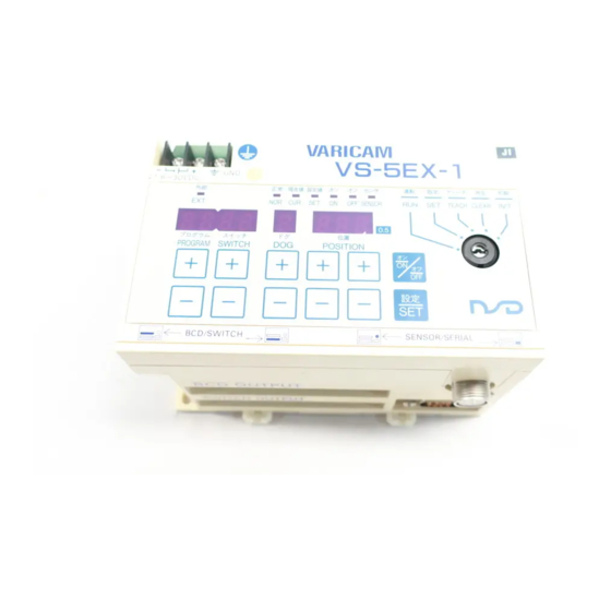
Outer Dimensions Controller Outer Dimensions 3-1. ●VS-5E (VS-5E-1 model has same dimensions.) Unit: mm VARICAM V S - 5 E LINE 100VAC NOR. CUR. SENSOR TEACH CLEAR INIT SWITCH POSITION SWITCH SENSOR/SERIAL 2-M4 SWITCH OUTPUT Mounting Hole 1 : 2 ●VS-5ED (VS-5ED-1 model has same dimensions.) VARICAM LINE... - Page 16 ●VS--5EX ( VS-5EX-1 model has same dimensions.) Unit: mm VARICAM V S - 5 E X LINE 100VAC EXT. NOR. CUR. SENSOR TEACH CLEAR INIT PROGRAM SWITCH POSITION BCD/SWITCH SENSOR/SERIAL BCD OUTPUT 2-M4 SWITCH OUTPUT Mounting Hole 1 : 2 ●Outer Dimensions when panel mounting fixture (VS-K05) is used.
-
Page 17: Sensor Outer Dimensions
Sensor Outer Dimensions 3-2. ●VRE-P062SAC Unit: mm ±1 71.5 ● Mounting hole dimensions for Servo mount ±0.1 3×M4 (hole evenly spaced) ; Depth: 5mm or more ±0.2 φ74 (φ17) ROBOTIC CABLE 3P-RBT (φ8) CONNECTOR R04-PB9M8.0A +0.03 φ56 H7 ( −0 φ16 ●VRE-P062SBC ●... - Page 18 ●VRE-P062FAC Unit: mm ● Mounting hole dimensions for Flange. □68 ±1 71.5 4 M5 (hole evenly spaced); Depth: 6mm or more φ74 ±0.2 4-R5 (φ17) ROBOTIC CABLE 4-φ6.5 +0.03 φ56H7( 3P-RBT (φ8) CONNECTOR R04-PB9M8.0A (52.3) φ16 ●VRE-P062FBC ● Mounting hole dimensions for Flange. □68 71.5 ±1...
- Page 19 ● VRE-P028SAC Unit: mm ● Mounting hole dimensions for Servo mount. ±0.5 3×M3 (hole evenly spaced); ±0.1 Depth: 4mm or more -0.1 ±0.5 ±0.2 ±0.5 φ36 (φ11) (φ5) ROBOTIC CABLE 3P-RBT +0.018 φ18 −0 CONNECTOR R04-PB9M5.2A φ16 ●A-13● Artisan Technology Group - Quality Instrumentation ... Guaranteed | (888) 88-SOURCE | www.artisantg.com...
-
Page 20: Extension Cable Outer Dimensions
Extension Cable Outer Dimensions 3-3. ●3P-S-0102-L and 3P-RBT-0102-L Unit: mm R04-PB9M8.0A R04-JB9F8.0A (42) (42) Note: Dimension L is given in terms of meters. External Cable Outer Dimensions 3-4. ●VS-C05-L L±50 FCN-367J040-AU/F Note: Dimension L is given in terms of meters. ●A-14●... -
Page 21: Model List
Model List Select the appropriate Model from the Table below. Name Model Description Controller VS-5E 1Program, 24-point output, Power voltage 100VAC VS-5ED 8 Programs, 24-point output, Power voltage 100VAC 16 Programs, 40 point output; or 32 Programs, 24-point output, Power VS-5EX voltage 100VAC VS-5E-1... -
Page 22: Introductory Section
B. Introductory Section Artisan Technology Group - Quality Instrumentation ... Guaranteed | (888) 88-SOURCE | www.artisantg.com... -
Page 23: Installation
Installation The handling procedures from the point of delivery to system installation are described in this section. Checking The Contents of The Shipping Case 5-1. Open the packing case, and verify that all items are present. (1) Controller ① ② ③... -
Page 24: Mounting Procedure & Precautions
Mounting Procedure & Precautions 5-2. The Controller and Sensor installation procedure and precautions are described in this section. Refer to item 3 (Outer Dimensions) at the Specifications Section for further mounting information. Controller Mounting Procedure & Precautions 5-2-1. When installing the Controller, the following conditions and precautions should be observed. ●Installation Site The following conditions should be satisfied: 1) The Controller should not be exposed to direct sunlight. -
Page 25: Sensor Mounting Procedure & Precautions
Sensor Mounting Procedure & Precautions 5-2-2. ●Sensor Handling Item Description Never drop the Sensor, or subject it to excessive forces or shocks. Avoid stepping on, or applying excessive stress to the cable. ●Sensor Body Item Description Remarks (1) Mounting dimensions ①Refer to the outline drawing for the Sensor model in question to determine the mounting dimensions. - Page 26 ●Sensor Shaft Mounting Procedure Item Description Remarks (1) Coupling of Machine A `direct-link` format ① Be sure to use a coupling device to link the 2 shafts. shaft and Sensor shaft will result in shaft (Refer to Appended Fig.1 for the recommended coupling fatigue and/or breakage device specifications.) after a long periods.
- Page 27 ●Coupling Device Selection and Handling Item Description Remarks (1) Coupling device A larger than ① Selection of the coupling device should be based on the selection precautions necessary coupling following factors: device will increase Amount of mounting permissible error Permissible shaft the ‘mounting error’...
-
Page 28: Wiring & Connections
Wiring & Connections Power Supply Connection 6-1. (1) Power Supply -The power cable should be as thick as possible to minimize voltage drops. -Twist the power cable. -For crimp type terminals, use the R3 type. (2) Ground -Be sure the unit is securely grounded in order to prevent electrical shocks. -The cable should be as thick as possible. -
Page 29: Connector Connections
Connector Connections 6-3. Connector Names & Functions 6-3-1. Sensor connector [2] BCD connector (For Program No. inputs and BCD OUTPUT current position outputs) Serial communication connector [1] Switch output connector (For connection to personal SWITCH OUTPUT computer, etc.) (For switch outputs, etc.) The VS-5ED and VS-5EX Models are equipped with input/output connector [2]. -
Page 30: Circuit Diagram
Circuit Diagram 6-3-3. (1) Outputs [1] Switch outputs, System Ready, timing [2] Current position and latch pulse pulse, and Program No. Internal circuit Internal circuit Display Switch outputs 1-24 System Ready 30VDC Max. Timing Pulse 0V output common 30VDC Max. (2) Inputs Internal circuit +24V input common... -
Page 31: Connector Pin Configuration & Signal Names
Connector Pin Configuration & Signal Names 6-3-4. (1) For VS-5E and VS-5ED Models [1] Switch Output Connector (for VS-5E and VS-5ED) [Connector Model: FCN361J040-AU/FCN-360C040-E] (Fujitsu Co.) This drawing shows the arrangement of pins as Pin No. Signal Name Signal Name Pin No. - Page 32 (2) For VS-5EX Model ● ● ● ● When using a 16-Program, 40-switch output format [1] Switch Output connector [Connector Model: FCN361J040-AU/FCN-360C040-E] (Fujitsu Co.) Signal Name Signal Name Pin No. Pin No. Switch output 1 Switch output 17 This drawing shows the arrangement of pins as Switch output 18 Switch output 2 viewed from the soldering terminals.
- Page 33 ● ● ● ● When using a 32-Program, 24-switch output format [1] Switch Output connector [Connector Model: FCN361J040-AU/FCN-360C040-E] (Fujitsu Co.) Signal Name Signal Name Pin No. Pin No. Switch output 1 Switch output 17 This drawing shows the arrangement of pins as Switch output 2 Switch output 18 viewed from the soldering terminals.
-
Page 34: Signal Timing
Signal Timing 6-3-5. (1) Program No. Input & Switch Output (For VS-5ED and VS-5EX) When the Program No. is changed by an external input, the output timing will be as shown below. Assuming that power is switched Change to Program No.4 ON with Program No.2 selected. - Page 35 (3) Current Position Output When HOLD Input is Operative Current position t1: Time period from the point when the HOLD Data HOLD value output input occurs, until the point when a “data hold” status is established. (ms) t1≦10 t2: Time period from the point when the HOLD input is canceled, until the point when data sampling is resumed.
-
Page 36: Operation Section
C. Operation Section Unless otherwise specified, the operation procedures described in this section apply to the VS-5ED Model. If the VS-5E Model is being used, please ignore the PROGRAM display items. Operation procedures for the VS-5EX Model are identical to those for the VS-5ED Model. -
Page 37: Operating Sequence (Flowchart)
Operating Sequence (Flowchart) An operation flowchart is shown below. The Basic operation steps are shown in the shaded boxes. For advanced operations, the steps shown in the boxes are also required. 2. Switch Output Setting are 1. -
Page 38: Operation
Operation The VS-5E Series becomes operative when the following 5 operations are performed. Item Description 1) Switch power ON 2) Set the sensor rotation direction Designate the direction in the angular value increases. Move the machine to the origin point position, then designate that 3) Set the origin point position as “zero”... -
Page 39: Sensor Rotation Direction Setting
Sensor Rotation Direction Setting 8-2. Designate the sensor rotation direction in which the angular value is to increase. 1 1 1 1 Set the key-switch to the INIT position. TEACH CLEAR Set the mode selector key-switch to the INIT position in order to INIT designate the rotation direction. -
Page 40: Switch Output Setting
Switch Output Setting 8-4. 1 1 1 1 Set the key-switch to the SET position. Setting Example TEACH CLEAR ON Position 125.5 INIT OFF Position 234.5 Switch output 125.5 234.5 2 2 2 2 Designate the Program No. 1 Program No. range: Doesn’t apply to VS-5E Model. - Page 41 6 6 6 6 Press the [ON/OFF] key. SENSOR - This establishes the OFF position setting mode. The OFF LED should be lit at this time. 0 0 0 0 ..5 5 5 5 7...
-
Page 42: Run
8-5. Switch outputs will switch ON and OFF according to the designated setting values during Run. 1 1 1 1 Select the desired Program No. Not required for VS-5E Model. ① Set the key-switch to the SET position. TEACH CLEAR INIT ②... -
Page 43: Advanced Operation
Advanced Operation Initial Settings 9-1. In order to use the VALICAM functions, those required functions must first be designated at the initial settings. In this section, the initial setting procedure will be explained. In the Initial Setting List shown below, the factory setting values (default values) are shown in [ ]. Unless another setting is desired, these setting items can be skipped. - Page 44 Applicable Model Setting Initial No. Item Description Setting Procedure VS-5E VS-5ED VS-5EX page No. Output status in Select the output status, which is to Output OFF: [0] 94 SET mode exist when the key-switch setting is Output HOLD: 1 changed from the RUN mode to another mode.
-
Page 45: Basic Initial Setting Procedure
Basic Initial Setting Procedure 9-1-2. Initial settings are designated as described below. 1 1 1 1 Set the key-switch to the INIT position. TEACH CLEAR INIT All initial settings are designated with the key-switch set to the INIT position. 2 2 2 2 Designate the Initial No. -
Page 46: Designation Of Vs-5Ex Output Specifications (Designated For Vs-5Ex Model Only
Designation of VS-5EX Output Specifications 9-1-3. (Designated for VS-5EX Model Only) The setting procedure described below should be executed immediately after delivery. 1 1 1 1 Set the key-switch to the INIT position. TEACH CLEAR INIT 2 2 2 2 Designate Initial No. -
Page 47: Protected Switch Function
Protected Switch Function 9-1-4. 1 1 1 1 Set the key-switch to the INIT position. TEACH CLEAR INIT 2 2 2 2 Designate Initial No. “96”. In order to select Initial No. “96”, first designate “97”,then 96 execute the procedure shown below. 97... -
Page 48: Canceling The Protected Switch Function
Canceling the Protected Switch Function 9-1-5. 1 1 1 1 Set the key-switch to the INIT position. TEACH CLEAR INIT 2 2 2 2 Designate Initial No. “96”. In order to select Initial No. “96”, first designate “97”, 96 then execute the procedure shown below. 97... -
Page 49: Current Position Value Setting
Current Position Value Setting 9-1-6. This setting operation is the equivalent of the “origin set” operation. However, with this procedure, there’s no need to move the machine to the origin point position. Instead, the current position value for a given position is designate by a numeric input. 1... -
Page 50: Designating The Switch Output Settings
Designating The Switch Output Settings 9-2. Setting The Switch Outputs by The TEACH Function 9-2-1. 1 1 1 1 Set the key-switch to the TEACH position. TEACH CLEAR INIT 2 2 2 2 Select the desired Program No. 1 PROGRAM ┼... - Page 51 7 7 7 7 Press the [ON/OFF] key. When the OFF LED is lit, the OFF position setting mode will be established. 8 8 8 8 Press the POSITION key. ┼ ┼ The current position value will be displayed. ─ ─...
-
Page 52: Designating Multi-Dog Settings
Designating Multi-Dog Settings 9-2-2. When designating switch output settings, up to 10 ON/OFF settings can be made for each output. These multi-dog settings can be designated either by the normal switch output setting format, or by the TEACH format. Set the key-switch to the SET or the TEACH position. To designate a multi-dog setting, enter the dog No. -
Page 53: Canceling Multi-Dog Settings
Canceling Multi-Dog Settings 9-2-3. The following procedure is used to cancel multi-dog settings. Set the key-switch to the SET or TEACH position. 1 1 1 1 Designate the dog No. to be canceled. 2 2 2 2 Designate the same setting value for both the ON and OFF positions. 3... -
Page 54: Canceling Switch Output Settings
Canceling Switch Output Settings 9-2-4. The settings for a given switch No., and for all switch Nos. larger than that No. are canceled. 1 1 1 1 Set the key-switch to the CREAR position. TEACH CLEAR INIT 2 2 2 2 Select the desired Program No. -
Page 55: Executing Run
Executing Run 9-3. Checking Setting Values During Run 9-3-1. Although the current position value is normally displayed during Run mode, the switch output settings can also be displayed. 1 1 1 1 With current position value displayed, press the [SET] key. The setting value will be displayed at the POSITION display. -
Page 56: Changing The Setting Values During Run
Changing The Setting Values During Run 9-3-2. Setting values can be changed in 0.5 degree increments during Run, to enable fine adjustments. In order to perform this function, it must first be enabled by the Initial No. 92 setting. (For details, refer to sections 9-1-1 and 9-1-2.) 1... -
Page 57: Checking Switch Outputs From Run Mode
Checking Switch Outputs From RUN Mode 9-3-3. The ON/OFF statuses of 6 switch outputs can be simultaneously displayed at the “Position” display area for verification. (1) (2) (3) ON: − 1 01 1 OFF: (Indicator OFF) (4) (5) (6) PROGRAM SWITCH DOG POSITION 1... -
Page 58: Errors
Errors Error causes and countermeasures are described below. Error Displays & Countermeasures 10-1. When a Controller or Sensor error occurs, there will be an error display, and an error signal output. When this occurs, refer to the following Table to determine the cause and the appropriate countermeasure. ●... - Page 59 3-31-23, Osu, Naka-ku, Nagoya, Japan 460-8302 Phone: 052-261-2352 Facsimile: 052-252-0522 Artisan Technology Group - Quality Instrumentation ... Guaranteed | (888) 88-SOURCE | www.artisantg.com...
Need help?
Do you have a question about the Varicam VS-5E Series and is the answer not in the manual?
Questions and answers