Advertisement
Quick Links
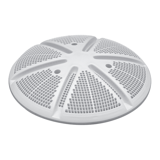
10" ULTRA RETRO SUCTION OUTLET
640-213x V
INSTALLATION INSTRUCTIONS
Designed,
Engineered &
Manufactured
in the USA.
2200 East Sturgis Road, Oxnard CA 93030 • Phone 805.981.0262 • Fax 805.981.9403
www.waterwayplastics.com • waterway@waterwayplastics.com
©2021 Waterway Plastics
810-0256-2017.0521
Advertisement

Related Manuals for Waterway 640-213 V Series

Summary of Contents for Waterway 640-213 V Series
- Page 1 10" ULTRA RETRO SUCTION OUTLET 640-213x V INSTALLATION INSTRUCTIONS Designed, Engineered & Manufactured in the USA. 2200 East Sturgis Road, Oxnard CA 93030 • Phone 805.981.0262 • Fax 805.981.9403 www.waterwayplastics.com • waterway@waterwayplastics.com ©2021 Waterway Plastics 810-0256-2017.0521...
-
Page 2: These Instructions
178 gpm floor / 132 gpm wall Body Suction Entrapment: A negative pressure applied to a large portion of the body or limbs can result in an entrapment. USE ONLY GENUINE WATERWAY REPLACEMENT PARTS. ©2021 Waterway Plastics 810-0256-2017.0521... - Page 3 • Do not exceed the safe flow rating of SOFAs as listed. • All SOFAs should be installed in accordance with Waterway installation instructions. • Under no condition should SOFA special flow rating be exceeded while the pool is open.
- Page 4 Do not exceed the safe flow rate. Do not increase flow through system by increasing pump size or horsepower. Do not allow children to sit, play or interact with main drains or suction outlet. ©2021 Waterway Plastics 810-0256-2017.0521...
- Page 5 B - Minimum Sump Depth: 0” C - Minimum Ledge Depth: 1” D - Minimum Ledge Width: 1/2” E - Minimum Pipe Offset: 1/2” F - Minimum Length Before Reduction: 16” Pipe Orientation: Vertical to pool surface ©2021 Waterway Plastics 810-0256-2017.0521...
- Page 6 4. Assorted screws, fasteners, and plastic spacers for attaching drain cover support plate to pool or spa surface (see Figure 1) See the following Installation Instructions to determine which components you will need to use for your installation. QTY. Figure 1 ©2021 Waterway Plastics 810-0256-2017.0521...
- Page 7 10" Ultra Retro Suction Cover 819-0910 #10 x 5/8" Self-Threading Screw 819-0912 #10 x 7/8" Self-Threading Screw 819-0911 #10 x 1 1/4" Self-Threading Screw 819-0999 #8-32 x 3/4" Screw 642-3180 Support Plate 642-3220B Spacer Bushing 821-0010 #10 Plastic Anchor ©2021 Waterway Plastics 810-0256-2017.0521...
-
Page 8: Installation Instructions
Distance Between Pool Surface Type of Self-Threading Screw and Tops of Screw Hole 0 - 1/4" #10 x 5/8" 1/4" - 1/2" #10 x 7/8" 1/2" - 3/4" #10 x 1 1/4" ©2021 Waterway Plastics 810-0256-2017.0521... - Page 9 If the drain cover support plate is not firmly in place, re-read these instructions and try another installation method (perhaps 3c above). Figure 6 ©2021 Waterway Plastics 810-0256-2017.0521...
- Page 10 INSTALLATION INSTRUCTIONS 6. Attach the drain cover (#2) to the drain cover support plate (#8) using the tool and the three #10 x 7/8 security screws provided. Waterway requires the use of security screws to secure the cover. Apply 20 In-Lbs torque to security Torx Cover Screws.
- Page 11 For product registration visit: www.waterwayplastics.com. For Warranty questions or claims please contact point of purchase. Designed, Engineered & Manufactured in the USA. 2200 East Sturgis Road, Oxnard CA 93030 • Phone 805.981.0262 • Fax 805.981.9403 www.waterwayplastics.com • waterway@waterwayplastics.com ©2021 Waterway Plastics 810-0256-2017.0521...
Need help?
Do you have a question about the 640-213 V Series and is the answer not in the manual?
Questions and answers