
Related Manuals for Trigon Epilog


Summary of Contents for Trigon Epilog
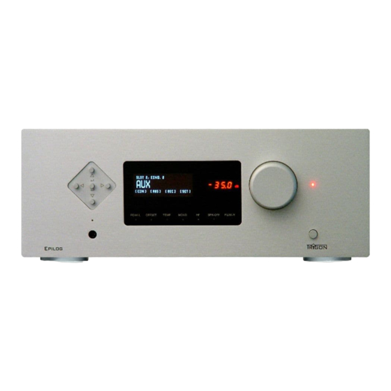
- Page 1 INSTRUCTION MANUAL INTEGRATED AMPLIFIER Epilog PEAK-L OFFSET TEMP MONO SPK-OFF PEAK-R Epil og...
-
Page 2: Table Of Contents
Installation Warranty and Service Operation Front Panel Controls Connections – Rear Panel Quick Start Instructions Setup and Menu Structure Unity Gain EPILOG with DIRECTOR Remote Control Modules UNBAL-INPUT Module BAL-INPUT Module UNBAL-OUTPUT Module BAL-OUTPUT Module PHONO-INPUT Module DIGITAL-INPUT Module What if... -
Page 3: Preface
Keep this manual for future reference; it is intended as a tool to help you make the best use of your new amplifier. Enjoy your new integrated amplifier! Best wishes from your TRIGON - team. 2. GENERAL DESCRIPTION Epilog is an integrated amplifier that can be individually adjusted in the pre stages to the needs of the user by the use of modules. -
Page 4: Safety
Due to the complex cabinet construction sound may be best avoided by microphonics. 2.1 Safety TRIGON ELEKTRONIK GMBH assumes no liability for any damage caused by improper handling, or failure to follow safety instructions. Amplifiers must not be installed in close proximity to heat sources such as radiators, stoves, high power light sources, open flames, etc... -
Page 5: Warranty And Service
By choosing the integrated amplifier, you have purchased a high quality and technologically advanced product. In order to meet TRIGON's requirements, every product must undergo numerous quality tests in every stage of production and a rigorous outgoing inspection. Furthermore, TRIGON ELECTRONICS GmbH offers a limited 3-year warranty on all products. - Page 6 The first step will be to plug the included TRIGON VOLT power cord to the power imput socket (24) at the rear side and the AC plug to the mains. Now turn on the power supply with the switch (23) on the back.
-
Page 7: Front Panel Controls
CAUTION in GERMANY CONSUMPTION 40 - 850W Epilog To power the on completely, press the on-off button (1) on the front of Epilog . LEDs (2) on the front panel flashes while a few relay click softly. Once the... - Page 8 Epilog NOTE: We have the equipped with a very low-power standby power supply. The power consumption is less than 1 watt in standby mode, ie you can Epilog always leave the connected in standby mode to mains without completely power off using the power switch (23).
- Page 9 5) on again. (5) Display: The display gives you information about the different operating states of the Epilog Director, It can switch off by the remote controller if you only want to see information when you make a change.
- Page 10 A further press of this button triggers the mono sound and LED (16) disappears. (17) LED HF The frequency bandwidth of Epilog is very wide. Therefore, under certain circumstances the output stages can start oscillating. A not perfectly matched combination of speaker cable, crossover and loudspeaker chassis can form a resonant circuit which, in conjunction with a broadband amplifier, can built an oscillator.
- Page 11 When the speakers are turned off in this menu, even the LED (11) via the headphone jack (12) lights up additionally. 3.2 Connections on the back Epilog Up to five modules (20) can be inserted at the back of the main chassis.
-
Page 12: Quick Start Instructions
Here the power cord is plugged. Always pay attention to the correct mains voltage. As standard, the epilogue is set for a mains voltage of 230 V AC. Have been set the Epilog for different voltages, then corresponding notes are (sticker) at the amp. - Page 13 3.4 Settings and Menus Epilog The concept of the provides an intuitive user interface. Nevertheless, this component provides useful additional features that are "hidden" in sub-menus. Epilog´s To fully take advantage of the capabilities, we recommend taking the time to read the following.
- Page 14 Display structure: The first line of the display indicates the number of the first occupied slot and the type of module present. As long as no specific name for an input has been set, it will be automatically designed as INPUT 1 in the second line of the display. The third line indicates the sub-menus for the configuration of the module and general setup.
- Page 15 Use key to navigate to the next menu to the right, e.g. [OUT] Likewise, key takes you in the opposite direction (left). Editing the [IN] Menu: After high-lighting the [IN] menu enter the desired menu with key (10) to get the sub- menu screen below: Now you are in the [IN] sub-menu, where you can edit the following settings: ■] INPUT...
- Page 16 Press key to select the next item. (10) again ■] Name - - - - - - - - - Select a name for the selected input from a list with keys and (8). This name will - - - - - - - - - INPUT be displayed when that input is selected.
- Page 17 Now you are in the [OUT] sub-menu, where they can make the following adjustments: ■] OUTPUT 1 1. Selecting the output to be edited SLOT 8 ] Reverse 2. Reverse cannels ■] OUTPUT 1 SLOT 6 On the first line select the output be edited with the keys (7) and (8). In this line you can also see the slot in which the module is installed, so that you can assign the output as desired.
- Page 18 This menu allows to link a specific input to the Record Out connectors on the "UNBALANCED OUTPUT" module, when installed. This function is only possible if at least one module "UNBALANCED OUTPUT" is installed in a slot. Using the keys you can select the input to be fed to the REC OUT connectors.
- Page 19 Various sub-menus can be accessed with key (10) (down) and key (up). [■] Vol. Base Level This function allows setting the initial volume level assumed by the EPILOG upon turn-on. This value can be set with the volume knob or with keys (8).
- Page 20 The currently installed Software version is displayed in the first line, after the TRIGON logo. The second line [INS] displays the information about installed input modules and number of available inputs. The third line [OUTS} displays the information about installed output modules and number of available outputs.
-
Page 21: Unity Gain
User mode display. The red volume display will reflect the currently selected level. 3.5 Unity Gain If the epilogue should be looped in a surround setup, because the two main speakers Epilog are connected at , then it may be useful to adjust the volume setting on the Epilog surround amplifier only. - Page 22 Now the volume control is bypassed for the selected input. With button (10) you leave the UNITY GAIN menu. To switch off UNITY GAIN again, you go back into the UNITY GAIN menu and press the arrow key (7). Now, the volume is adjustable by using the volume button (3) for this input again.
- Page 23 The DIRECTOR is a system remote control, which can remotely control various devices from TRIGON. The entire keyboard can be used three fold. Individual function levels are provided for control of amplifiers, CD players and tuners. The key (1), top right, next to the device LED's, selects which type of device is controlled.
- Page 24 Epilog Note: All settings are retained even after turning off of . However, when the display is switched off, it will come on briefly whenever an adjustment is made to the Epilog . For example, when the volume is changed, the change is shown briefly before the display is switched off again.
-
Page 25: Modules
Currently we offer four different modules (see below). The concept of Epilog is so designed that we already have more of TRIGON modules in the Epilog design and the fact with each new module is always interesting. -
Page 26: Unbal-Output Module
Pin-1 = Ground Pin-2 = Signal + Pin-3 = Signal – Epilog Up to five BAL-INPUT modules can be used in one 4.3 UNBAL-OUTPUT module UNBAL-OUTPUT D ial o g This module contains one single-ended MAIN preamplifier MAIN output with adjustable volume and a RECORD output to connect a recording device. - Page 27 Please refer to the tables [A] and [B] for the adjustable values. Also, the gain of the PHONO module must be adapted to the used pickup. This Epilog setting is made on the front of the . Two PHONO modules can be installed...
- Page 28 The module PHONO can be optimally adjusted to the used pickup of the turntable. The value can be taken from the operating instructions manual of the pickup. The available adjustment values are listed in Tables [A] and [B]. Table [A] shows the values for a capacitive adjustment, as is required for MM cartridges.
- Page 29 4.6.5 Table B Switch settings for the input resistors 100p 47p 1800 1000 470 Input resistance calculated in Ohm 47000,0 1733,6 979,2 634,2 465,3 369,8 317,6 269,9 219,0 195,2 179,6 163,3 149,4 137,9 130,0 121,2 99,8 94,5 90,7 86,4 82,3 78,7 76,1 73,0...
- Page 30 Phono module to the respective pickup. To access the menu for the gain setting, you select the Phono module with the input Epilog selector buttons and then press the button (10) of the . Now you should see the following screen.
- Page 31 : 40 x 73,5 x 173,5 mm ( BxHxT ) 4.7. DAC Modul Four digital source devices can be connected to the DAC module. Use the arrow Epilog keys (7) and (8) on the front panel of the to choose the input. Following...
- Page 32 Epilog To avoid damage to the to your system, please connect only digital source devices to the DAC module! The module can not handle analog signals at the inputs, and also the source device could suffer damage. 4.7.1 The necessary Software...
- Page 33 Epilog default drivers. The computer treats the now as a separate USB sound card. The maximum resolution is 24-bit 96 KHz at this entry. 4.7.3 The settings and menus As described in detail under 3.5.1, the names of the inputs can be set individually. In the initial state (factory setting), the coax digital inputs with the names shown in the following images A, B coax, and USB Opt appear.
-
Page 34: What If
Display when the USB input is selected. 4.7.4 Technical Data DAC Module Inputs : 2x Cinch SPDIF, 1x Toslink, 1x USB Distortion (THD + N) : < 0.03% : 20 Hz – 20 kHz (+-1dB) Frequency response (analogue) Signal / Noise ratio : -106 dB Weight : 350g... -
Page 35: It Hums
Try using a „ground breaker“ - These are readily available from good specialty dealers. 5.3 ... errors made by man or machine? Epilog has been designed to be used under normal operating conditions as a high quality audio amplifier for domestic use. Unrealistic test such as listening to a un-used input at high volume will result in noise coming from the speakers, which is perfectly normal. -
Page 36: Specifications
: -94 dB based on 1 Watt at 4 Ohm Weight : 25Kg Dimensions : 440 x 180 x 405 mm (WxHxD) subject to change 12.2019 Development and assembly: Trigon Elektronik GmbH Crumbacher Str. 60 D-34277 Fuldabrück - Bergshausen Germany Tel. +49 (0) 561/20753880 +49 (0) 561/20753888 e-mail: trigon@trigon-audio.de...
Need help?
Do you have a question about the Epilog and is the answer not in the manual?
Questions and answers