Advertisement
Quick Links
THANKS FOR CHOOSING ONE OF OUR KITS!
This manual has been written taking into account the common issues that we often find people experience in our
workshops. The order in which the components are placed on the board is meant to make assembly as easy as possible.
Some steps are not obvious, so even if you're an experienced DIYer please read the steps thoroughly before starting.
If this is your first project, please read this article before you start assembling the kit:
www.befaco.org/howto/
You will be soldering both boards at the same time. Keeping them in the panel together might help you through the build.
Check last pages of the Build for PCB pics to help you identify components, or follow the iBOM:
www.befaco.org/iBoms/plethora.html
BEWARE OF EXPOSED VIAS. This build is tight and you might short one if not careful.
HAVE FUN!
BAG A
RESISTORS
Color code can be difficult to identify, we strongly recommend to use a multimeter.
Qty
Value
Code
33
100k
Brown, black, black, orange, brown
14
1k
Brown, black, black, brown, brown
9
470
Yellow, violet, black, black, brown
8
91k
White, brown, black, red, brown
8
330k
Orange, orange, black, orange, brown
7
33k
Orange, orange, black, red, brown
4
220k
Red, red, black, orange, brown
4
120k
Brown, red, black, orange, brown
3
3M3
Orange, orange, black, yellow, brown
3
110k
Brown, brown, black, orange, brown
3
47k
Yellow, violet, black, red, brown
3
39k
Orange, white, black, red, brown
3
1k2
Brown, red, black, brown, brown
2
200k
Red, black, black, orange, brown
2
24k
Red, yellow, black, red, brown
2
10k
Brown, black, black, red, brown
2
1k5
Brown, green, black, red, brown
1
56k
Green, blue, black, red, brown
1
27k
Red, violet, black, red, brown
Name on PCB
R8, R9, R13, R15, R16, R22, R24, R33, R36, R37, R52, R53,
R54, R59, R61, R63, R65, R66, R67, R69, R76, R80, R84,
R85, R88, R89, R100, R103, R104, R105, R106, R107,
R111
R1, R3, R20, R21, R26, R27, R43, R44, R47, R70, R75,
R109, R110, R112
R82, R90, R91, R92, R93, R95, R96, R98, R99
R4, R11, R29, R32, R46, R48, R50, R60
R12, R14, R34, R35, R49, R51, R58, R62
R73, R81, R83, R86, R87, R101, R102
R17, R38, R55, R64
R5, R30, R68, R77
R19, R40, R57
R7, R23, R42
R6, R25, R45
R18, R39, R56
R2, R28, R41
R94, R97
R10, R31
R71, R72
R74, R108
R79
R78
1
Advertisement

Related Manuals for Befaco NOISE PLETHORA V1


Summary of Contents for Befaco NOISE PLETHORA V1
- Page 1 Some steps are not obvious, so even if you're an experienced DIYer please read the steps thoroughly before starting. If this is your first project, please read this article before you start assembling the kit: www.befaco.org/howto/ You will be soldering both boards at the same time. Keeping them in the panel together might help you through the build.
- Page 2 DIODE Solder the diodes observing their polarity. The black or white line on the diode must match with the white line on the diode symbol on the PCB silkscreen. Value Name on PCB 1N4148 D1, D2, D5 1N5817 (black) D3, D4 FERRITE To solder the two ferrite beads use a recycled resistor leg passed through each ferrite and proceed as if it were a resistor.
-
Page 3: Electrolytic Capacitors
ELECTROLYTIC CAPACITORS Values are written on the side of the capacitor. Mind their polarity (The long leg of the capacitor is the positive (+)). Value Code Name on PCB 10uF 10uF C6, C10, C26, C31, C37, C38, C52 2.2uf 2.2uf C5, C7, C11, C16, C25, C29 4.7uF 4.7uF... -
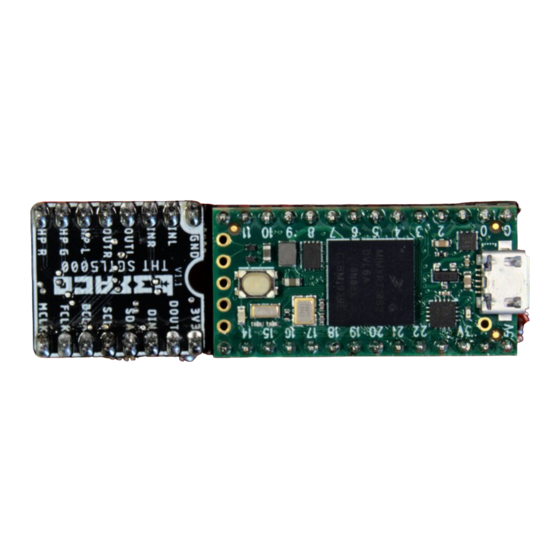
Page 4: Pin Headers
Place pin headers into the sockets, the long side of the pins that will fit in. Place Teensy (USB facing up) and codec (Befaco name facing up) boards on the pins, watch the footprint for the orientation. Do this gently. - Page 5 POGO PIN HEADER Remove the teensy and Place the Pogo pin header on the PCB, then place back the teensy pushing the pogo pins, Double check they all are perfectly straight and solder them. If not they might move and cause trouble! Size Place on PCB Between the 1x14 pins...
- Page 6 OPEN POTS BAG Be careful not to mix Pot and minijack nuts. They are similar but different. POTENTIOMETERS Now place the potentiometers on the PCB but... don't solder them yet! . Before going ahead, take this in consideration: * Check pot holes first. If some are too tight, make them bigger with thin tweezers. * Pots are really tight.
- Page 7 FINISH YOUR BUILD! - Screw in the parts in this order: A) Mini-jacks B) Pots and encoder. -Take off the Teensy and the Codec to be able to solder the points below. - Ensuring all of the above parts are flush with the panel and both PCB and panel are perfectly parallel. Then you can finally solder them! - Fit the LED on the panel holes and solder them - Flip the module and make sure that LED display is flat against the window and centered.
Need help?
Do you have a question about the NOISE PLETHORA V1 and is the answer not in the manual?
Questions and answers