
Related Manuals for TICA FCA 201 EC


Summary of Contents for TICA FCA 201 EC
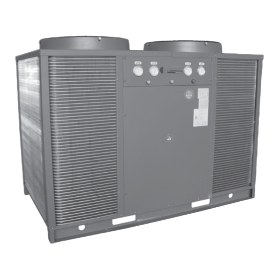
- Page 1 Installation, Operation & Maintenance Manual AIR-COOLED MODULAR CHILLER Chiller Products FCHI01-00...
-
Page 2: Table Of Contents
Contents Safety Precautions ....................2 Dimensions ......................3 Installation ......................8 Location and Clearance ................8 Lifting ..................... 8 Water System Installation .................11 Electrical Installation ................12 Commissioning ....................23 Pre-Start Checklist ...................23 Startup Procedure ..................Servicing and Maintenance ...................24 Troubleshooting ....................25 AIR-COOLED MODULAR CHILLER FCA/TCA 201-301 EC/EH FCA/TCA 201-301 NC/NH... -
Page 3: Safety Precautions
Safety Precautions Please read the following safety precautions carefully. Failure to follow safety precautions could result in death or serious injuries. Important: • Installation of equipment in corrosive, combustive or explosive environment is strictly prohibited. • Do not use Oxygen, Acetylene, poisonous or any other gas that will cause explosion during equipment leak test. Warning: • Installation and maintenance should be performed by qualified personnel who are familiar with the product, local codes and regulations. • The equipment must be installed according to local rules and regulations. • Field-installed wiring must comply with local codes and regulations, and must be carried out by qualified personnel. • Power supply must comply with unit’s name plate specifications. • The unit must be GROUNDED to prevent possible hazards due to insulation failure. -
Page 4: Dimensions
Dimensions Model: FCA 201 / 301 EC / EH Water Inlet Water Outlet FCA201 EC/EH 1030 FCA301 EC/EH 1073 536.5 Dimensions in mm Model: FCA 201 / 301 NC / NH Water Inlet Water Outlet Dimensions in mm Page 3... -
Page 5: Installation
Installation Location and Clearance • Unit must be installed on a flat concrete base which could withstand the weight of the unit. Vibration isolator should be installed to give a minimal unit vibration. • Do not install unit under explosive, combustive and corrosive environment. • Do not expose unit to direct sunlight. Unit should be installed under shaded or covered area. • Sufficient space must be allocated for water drainage, ventilation and service. Main water supply and return should be located at least 1 meter away from the unit for maintenance. Proper water drainage should be prepared for maintenance purpose. Caution: Every module has pre-set address via DIP switch setting on the PCB. Unit must be placed according to the numbering label on each module. -
Page 6: Lifting
FAC 201/301 NC/NH Air Suction Maintenance Air Discharge Air Discharge Air Suction Water Piping Water Piping Air Suction Air Suction Air Suction Air Suction Air Suction Air Suction Maintenance Water Piping Air Suction Chain Dimensions in mm Lifting Spreader bar Protection Unit should be wrapped and well-protected during transportation from the factory to the construction site. - Page 7 • The pipe size of each module is DN40. The pipe size of the chilled water supply and return are: Cooling / Heating Capacity, kW 120 230 350 465 580 Pipes diameter DN (mm) 100 125 150 170 • Make sure the chilled water supply and return pipe connections to heat exchanger are correct. • Install gate valve, pressure gauge and thermometer both at the chilled water supply and return pipes for ease of service and maintenance work. Pressure gauge and thermometer should be installed at visible and accessible location. • Strainer should be installed at water inlet of every module and before water pump to filter off foreign particles from entering water pump and heat exchanger. • Balancing valve should be installed at every module to ensure every module has same water pressure drop. The temperature difference between water inlet and outlet normally will be 5°C.
-
Page 8: Electrical Installation
Leak Test Testing pressure for water pipe should be greater than 1.25 times the working pressure, and should not be less than 0.6MPa. Piping system is considered leak free if pressure drop is less than 0.02MPa after 5 minutes of pressure test. Water pressure test should not be carried out at ambient temperature lower than 5˚C. Pressure gauge should be well-calibrated with step precision of not less than 1.5; full scale value should be 1.5 to 2 times the biggest tested pressure reading. - Page 9 Wiring Diagram Model: FCA 201 EC/NC (Single / Master) Page 8...
- Page 10 Model: FCA 201 EC/NC (Slave) Page 9...
- Page 11 Model: FCA 201 EH/NH (Single / Master) Page 10...
- Page 12 Model: FCA 201 EH/NH (Slave) Page 11...
- Page 13 Model: FCA 301 EC/NC (Single) Page 12...
- Page 14 Model: FCA 301 EC/NC (Master) Page 13...
- Page 15 Model: FCA 301 EC/NC (Slave) Page 14...
- Page 16 Model: FCA 301 EH/NH (Single) Page 15...
- Page 17 Model: FCA 301 EH/NH (Master) Page 16...
- Page 18 Model: FCA 301 EH/NH (Slave) Page 17...
- Page 19 Control Module Setting and Description a) Input Signal Input Signal Description Type of control IN_1 Flow switch IN_2 Cooling low pressure #1 IN_3 High pressure #1 IN_4 Compressor #1 overload IN_5 Heating low pressure #1 IN_6 Power supply or phase failure IN_7 Cooling low pressure #2 IN_8...
- Page 20 Controller Features and Algorithm 1) Features a) Multi colour backlight LCD display. b) Individual or modular control. c) Real time clock. d) 7days real time ON/OFF setting. e) Leaving/entering water temperature display. f) Various control parameters setting. g) Manual defrost. h) Last state memory. i) Key lock function. Error codes display area Address Mode...
- Page 21 4) Functions a) ON/OFF Press key to switch ON/OFF the system. b) Date/Time Setting To set clock, press <SET> key to enter time setting menu, “Time display area” will show “SET CLOCK” to indicate time setting mode. Press <TIME +/-> key to change the minute value and hold the <SET> key to change the hour value. Press <SET> key again to enter date setting menu, “Time display area” will show “SET DAY” to indicate date setting mode, press <DAY> key to set day value.
- Page 22 Operating Parameters Display Press <SET> key 3 times (press 2 times and hold 1 sec for third time) will enter Operating Parameters Display. “Error codes display area” will show “d1”; “Address display area” will show sub-menu number (13 sub-menu) and “Temperature display area” will show the particular sub-menu. Press the following to change the settings. Press <MENU +/-> for sub-menu selection. and + to change the parameter settings. Press Press <ENTER> key to save the settings and exit. Press <CANCEL> to reject selection and exit without saving. The parameters will be represented as in the following table: Sub-menu Description Default Range Operation mode...
- Page 23 n) Error Codes Display When the unit is facing operational problem, the “Error codes display area” will display error codes to indicate the problem detected the interpretation of the codes are as following: Error Code Description Setting Power supply fault Wrong phase, over/under voltage Low water flow error - system If water temperature difference >9°C (FCA301 only) Reserved Ambient temperature sensor (TH7) error Ambient sensor open/short...
-
Page 24: Commissioning
Commissioning Pre-Start Checklist Model: Serial No: Air side system Yes / No Electrical connections correct? Fan rotation correct? Free to rotate? No air trapped in the heat exchanger and piping? Chilled water system Yes / No Pressure gauge and thermometer installed and functional? Make-up water supply installed and functional? Piping work proper installed? Water pressure head on chilled water return OK (5m H2O or above)? Chilled water piping clean? -
Page 25: Servicing And Maintenance
Service And Maintenance To prolong the lifespan of the chiller and also to reduce unnecessary down time, it is strongly recommended to perform scheduled inspection and maintenance as follows: • Inspect the condenser coils for dirt and debris. Clean condenser coil if necessary. • Inspect all the piping components. Clean strainers and replace if necessary. • Check and tighten all the wiring connection as necessary. • Drain out the water completely if the unit is not operating for a long period. • Perform leak test on refrigerant system if pressure drop occurs. Evaporator The construction of the evaporator does not allow it to be cleaned mechanically. However, chemical cleaning should be adopted, by the following: • Use only chemical additives from authorized dealer. • Use the right amount of chemical according to cleaning direction. Follow exactly the cleaning or neutralizing procedure after cleaning. • It is recommended to engage professional water treatment personnel to perform chemical cleaning. CAUTION: EXCESSIVE TREATMENT AND INAPPROPRIATE CHEMICAL CLEANING OF WATER CAN CAUSE MORE HARM THAN NONE AT ALL. DAMAGE COULD BE DOBE TO OTHER SYSTEM COMPONENTS LIKE PUMP, COOLING TOWER, PIPING AND ETC. -
Page 26: Troubleshooting
Troubleshooting Fault Possible Causes The compresser does not Power failure or communication bus failure operate "ERR CODE" display on controller Module in pre-heat condition Wrong controller setting Compressor frequent cut in / cut Insufficient refrigerant Low water flow Compressor noise Power failure or wrong phase sequence Refrigerant flow back Compressor mechanical part failure...
Need help?
Do you have a question about the FCA 201 EC and is the answer not in the manual?
Questions and answers