Table of Contents
Advertisement
Quick Links
Advertisement
Table of Contents

Related Manuals for Viqua PRO24-100


Summary of Contents for Viqua PRO24-100
- Page 1 Owner’s Manual Models: PRO24-100 PRO24-186 Powered by 425 Clair Rd. W, Guelph, Ontario, Canada N1L 1R1 t. (+1) 519.763.1032 • tf. (+1) 800.265.7246 (US and Canada only) t. (+31) 73 747 0144 (Europe only) • f. (+1) 519.763.5069 e-mail: info@viqua.com www.viqua.com...
- Page 2 • VIQUA replacement lamps undergo rigorous performance testing and strict quality control processes to ensure that the safety and performance certifications of the original equipment are not compromised. So, you can see that it's simply not worth the risk! Insist on genuine VIQUA replacement lamps.
-
Page 3: Safety Information
Safety Information Section 1 Safety Information These are the original instructions.Please read this entire manual before operating this equipment. Pay attention to all danger, warning, and caution statements in this manual. Failure to do so could result in serious personal injury or damage to the equipment. -
Page 4: Water Chemistry
Safety Information WA R N I N G • During extended periods of no water flow, the water in your chamber can become very hot (Approx. 60 °C) and potentially lead to scalding. It is recommended to run your water until this hot water has been purged from your chamber. Do not allow water to contact your skin during this time. To eliminate this condition, a temperature management valve can be installed at the outlet of your UV system. -
Page 5: General Information
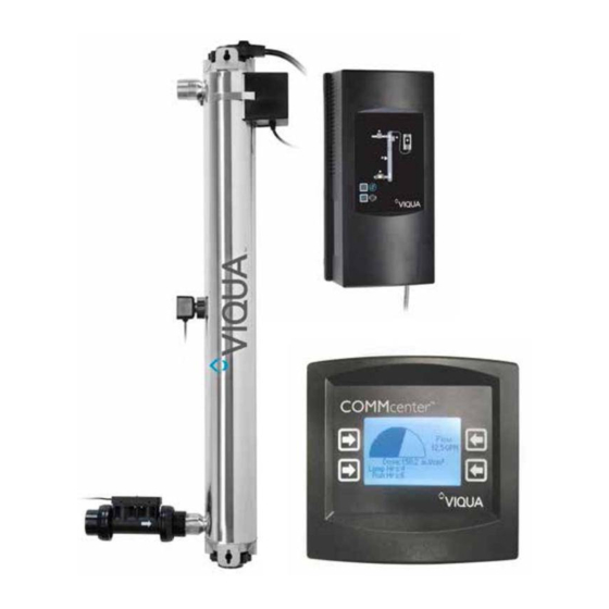
Proper pre-treatment is essential for the UV system to operate as intended. Section 2 General Information Figure 1 System Components Note: PRO24-186 system shown. PRO24-100 systems only have one controller and one chamber. Item Description Part Number UV Systems... -
Page 6: Dimensions And Layout
General Information O-ring 002233 Used for all systems Bottom bolt (includes screw) 603053 Used for all systems Item Description Part Number UV Systems Sleeve removal tool 602988 Used for all systems Flow meter sensor 410982R-30 Used for all systems Sensor 650580 Used for all systems COMMcenter... - Page 7 General Information Dimensions and Layout for PRO24-100 41’’ Clearance for lamp removal OUTLET 41’’ INLET 3’’ min Figure 2 System - Dimension and Layout Item Description Function Sample valve Allows for sampling of raw water. Pre-treatment allows the UV system to operate effectively. The water should meet Pre-treatment certain water quality parameters before entering UV System.
-
Page 8: Pipe Lengths
Installation Item Description Function Allows water supply to be shut-off when proper performance cannot be assured. Note: If the ground from your electrical panel is tied to your copper water lines, and you are using a Plastic Body solenoid valve, installation of an approved ground strap is Solenoid valve required. - Page 9 Installation Procedure: • Connect the sleeve bolt at the • Install the UV Chamber • Connect Flow Meter Sensor • Install the sensor to the UV bottom of the sleeve vertically with a 37.5” spacing to the primary chamber using system.
- Page 10 Primary Controller and Primary Controller Secondary Controller COMMCENTER PRIMARY CONTROLLER SECONDARY CONTROLLER • Make connections for UV sensor, Commcenter, CoolTouch fan, Flow meter sensor and Solenoid valve (if applicable) following the diagram above. Note: For PRO24-100 systems secondary controller is not used.
-
Page 11: Cleaning Procedure
Installation • Connect controllers to a power bar or outlet. For PRO24-186 systems, ensure power to each controller is applied within 20 seconds. Note: Outlet must be protected by a Ground Fault Circuit Interrupter (GFCI). • Lamp ignition may take up to 25 seconds.Wait until lamp is fully warmed-up. - Page 12 • Reconnect the controller with out UV sensor. Note: PRO24-100 systems only have one controller. 30 mins • Remove cartridge(s) and • Connect only the filter • Open each faucets and turn •...
-
Page 13: Maintenance
Maintenance Section 4 Maintenance WA R N I N G • Always disconnect power before performing any work on the UV system. • Always shut-off water flow and release water pressure before servicing. • Regularly inspect your disinfection system to ensure that the power indicators are on and no alarms are present. •... - Page 14 Maintenance • Restore Power. • Lock the wire form into • Turn on the water supply. position. • Press and hold the “New Lamp” button for 5 seconds till you hear a beep or reset using CommCenter, Refer to How can I reset the lamp run hours after installing a new lamp?.
- Page 15 Maintenance Mild Acid • Remove O-ring from top of • Clean the sleeve with a cloth • Connect the sleeve bolt at the • Remove the sleeve. the sleeve. soaked in CLR, vinegar or bottom of the sleeve some other mild acid and assembly.
-
Page 16: Sensor Cleaning
Maintenance 4.3 Sensor Cleaning 30 mins Commercial Scale Remover Remove the UV sensor from the unit. Submerge the end of sensor for 30 minutes in Commercial Scale Remover and wipe with clean cotton swab. Once UV sensor is clean reassemble back into chamber. 4.4 Flow Meter Maintenance Inspect Flow Meter periodically to ensure that there is no fouling and the paddle wheel spins freely with no resistance. -
Page 17: Control Panel
Operation Section 5 Operation 5.1 Control Panel Figure 3 Control Panel Buttons and Display Feature Description Function Press to silence audible alarm. When the alarm is due to the lamp's age, the mute button will silence the audible alarm for 7 days; this Audible alarm mute may be repeated up to a maximum of 4 times. - Page 18 Operation 5.2 COMMcenter Navigation There are four buttons on the COMMcenter. Their function corresponds to what is displayed on the screen next to each button, as illustrated below Figure 4 COMMcenter Use this button to select “Settings”. Use this button to move up through options. This button does not have an assigned function on this screen.
- Page 19 Operation Screens with a double outline are only visible when in Advanced Menus mode. Tip: Most screens are numbered. Tip: Use the buttons on the right to navigate up and down the selections. View Power Saving Lamp Hours Stepped Set Point Dose Alarm Selection Variable Set Point...
- Page 20 One screen for each unit. Navigate between units using buttons on the Model Selection: Use buttons on right to select model right. PRO24-100 Note: The Home page for multiple systems is also useful as it displays the dose being delivered by each unit. It may be viewed by selecting the following:...
- Page 21 Operation How many more days should my lamp last? How can I reset the lamp run hours after installing a new lamp? Note: The “Lamp Hours” screens may only be viewed when in The lamp run hours can also be reset at the power supply. Refer to system Owner's Advanced Menus mode.
- Page 22 Operation How do I set the time? How do I set the date? The COMMcenter is equipped with a battery that will allow it to track the The COMMcenter is equipped with a battery that will allow it to track the date for the time for the life of the product.
- Page 23 This procedure resets the addresses of all units to “zero”. Use this only after will no longer track this unit. Use this when permanently removing a unit. This consulting with VIQUA Technical Services at 1-800-265-7246. way, if it is used again in another location, it will not have an assigned address.A Note: The “Maintenance”...
- Page 24 Operation How do I remove a unit? How do I re-install a unit? When this procedure is followed, the unit that is removed is no longer tracked Use this procedure when a unit that was previously removed from service (ex: by the COMMcenter.
-
Page 25: Alarms And Troubleshooting
Alarms and Troubleshooting How do I reset the COMMcenter? How do I reset the ballast unit? To reset a COMMcenter, hold down any two buttons diagonally opposite each To reset the ballast unit, hold down both buttons on the front of the unit while other while connecting it to a unit. - Page 26 Alarms and Troubleshooting 6.2 Alarms Alarm condition Unit 2 Solenoid (on either one or Unit 1 (Only for PRO24- COMMcenter Comments Valve both units) 186 systems) • Flashes warning to indicate • UV lamp ballast (controller) LED flashing red which component and unit (only Unit in alarm) UV lamp connector my not be in alarm...
- Page 27 Alarms and Troubleshooting 6.3 LOW UV ALARMS Use the following flow chart to troubleshoot a low dose alarm for the primary, secondary or both units. Low UV Alarms UV Sensor Amber Turn Off Clean System Water Supply Run @ 75-100% rated flow Green Normal...
-
Page 28: Data Logging
The COMMcenter has the ability to store data on the performance of your system(s) to a Micro-SD card, refer to Figure Micro-SD cards are available at Viqua or various Viqua Dealers. Information is recorded every minute and a 512MB card should store 18 years worth of information. -
Page 29: Dry Contact
Additional COMMcenter Operations 7.1.1.3 When Data-logging from Multiple Units When using a standard Ethernet (RJ45) cable to connect the COMMcenter to the first controller, it is important to note that power is provided to the COMMcenter through this cable. Therefore, if power to this unit is interrupted the COMMcenter loses power and data-logging is temporarily stopped. -
Page 30: Specifications
/hr) Electrical Voltage 100V-240 V / 50Hz/60Hz Max. current 2.5 A per unit 460 Watts (PRO24-186) Max. power consumption 230 Watts (PRO24-100) 400 Watts (PRO24-186) Lamp power consumption 200 Watts (PRO24-100) Port Size Combo Inlet and outlet 1¼” NPT, 1" FNPT... -
Page 31: Section 9 Manufacturer's Warranty
VIQUA warrants the electrical (controller) and hardware components to be free from defects in material and workmanship for a period of five (5) years from the date of purchase. During this time, VIQUA will repair or replace, at its option, any defective parts covered by the warranty. - Page 32 425 Clair Rd. W, Guelph, Ontario, Canada N1L 1R1 t. (+1) 519.763.1032 • tf. (+1) 800.265.7246 (US and Canada only) t. (+31) 73 747 0144 (Europe only) • f. (+1) 519.763.5069 e-mail: info@viqua.com www.viqua.com...
Need help?
Do you have a question about the PRO24-100 and is the answer not in the manual?
Questions and answers