Table of Contents
Advertisement
Quick Links
Advertisement
Table of Contents

Subscribe to Our Youtube Channel
Related Manuals for F5 BIG-IP 8950


Summary of Contents for F5 BIG-IP 8950
- Page 1 Platform Guide: 8950 MAN-0320-03...
-
Page 3: Table Of Contents
Table of Contents Table of Contents Legal Notices............................5 Chapter 1: About the 8950 platform..............7 The 8950 Platform........................8 Components provided with the platform...................9 Peripheral hardware that you provide..................9 LCD panel..........................9 About LCD menus.......................10 Using LCD menus.......................11 Indicator LEDs........................12 Indicator LED behavior....................12 Standard operating states of the status and Alarm LEDs..........13 Standard operating states of the power supply LEDs..........13 LED alert conditions....................13... - Page 4 Table of Contents Assigning a management IP address..................25 Licensing the platform......................26 Chapter 3: Platform Maintenance...............27 About AC power supplies.......................28 Installing an AC power supply..................28 About DC power supplies.......................30 Wiring the DC power supply terminal block..............31 Installing a DC power supply..................32 About the fan tray........................34 Replacing the fan tray....................34 About the hard drives......................35...
-
Page 5: Legal Notices
2011, F5 Networks, Inc. All rights reserved. F5 Networks, Inc. (F5) believes the information it furnishes to be accurate and reliable. However, F5 assumes no responsibility for the use of this information, nor any infringement of patents or other rights of third parties which may result from its use. - Page 6 Legal Notices can radiate radio frequency energy and, if not installed and used in accordance with the instruction manual, may cause harmful interference to radio communications. Operation of this equipment in a residential area is likely to cause harmful interference, in which case the user, at his own expense, will be required to take whatever measures may be required to correct the interference.
-
Page 7: Chapter 1: About The 8950 Platform
• Peripheral hardware that you provide F5 offers two performance levels of SSL offload in the 8950 series, • LCD panel the 8950 and the 8950S. Please see the data sheet on •... -
Page 8: The 8950 Platform
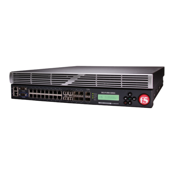
About the 8950 platform The 8950 Platform Before you install the 8950 platform, you may want to quickly review information about the controls and ports on both the front and the back of the platform. On the front of the 8950 platform, you can reset the unit using the LCD panel and view the indicator LEDs for hard disk access. -
Page 9: Components Provided With The Platform
Platform Guide: 8950 Components provided with the platform When you unpack the 8950 platform, you should make sure that the following components are included. Quantity Hardware power cables (black), AC power only DC terminal blocks, DC power option only failover cable (blue) console cable (beige) front-mounting kit rail-mounting kit... -
Page 10: About Lcd Menus
About the 8950 platform Figure 3: The LCD panel and control buttons About LCD menus There are three menus on the LCD panel. You can configure the display options to meet your needs. LCD config menu You can use the LCD config menu to adjust the display properties of the LCD panel. Option Description Backlight... -
Page 11: Using Lcd Menus
Platform Guide: 8950 System menu You can use the System menu to view options for rebooting, halting, and netbooting the hardware. This menu also provides options for configuring the management interface. Option Description Management Changes the management interface information. Select from the following options: •... -
Page 12: Indicator Leds
About the 8950 platform Halting the unit We recommend that you halt the unit before you power it down or reboot it using the LCD menu options. 1. Press the X button, then use the arrow keys to navigate to the System menu. 2. -
Page 13: Standard Operating States Of The Status And Alarm Leds
Platform Guide: 8950 Standard operating states of the status and Alarm LEDs When the unit is in a standard operating state, the Status and Alarm LEDs behave in a defined manner. System State Description Status LED Alarm LED Active mode Unit is active in a green solid off/none... -
Page 14: Additional Indicator Led Status Conditions
About the 8950 platform cd /config 3. Using a text editor, such as vi or Pico, open the /config/user_alert.conf file. 4. Add the following lines to the end of the file: alert BIGIP_MCPD_MCPDERR_POOL_MEMBER_MON_DOWN "Pool member (.*?):(.*?) monitor status down." snmptrap OID=".1.3.6.1.4.1.3375.2.4.0.10"; lcdwarn description="Node down"... -
Page 15: Viewing The Status Of A Specific Interface
Platform Guide: 8950 When using the tmsh interface command, you can either apply the command to all interfaces or to a specific interface key. Viewing the status of a specific interface You can use tmsh to view the status of a specific interface on a platform. 1. -
Page 16: About Interface Media Type And Duplex Mode
About the 8950 platform About interface media type and duplex mode All interfaces on the BIG-IP system default to auto-negotiate speed and duplex settings. We recommend that you also configure any network equipment that you plan to use with the BIG-IP system to auto-negotiate speed and duplex settings. -
Page 17: Viewing Valid Media Types For An Interface
Platform Guide: 8950 Viewing valid media types for an interface You can use tmsh to view the valid media types for an interface. Note: This platform may not support all of the media type options that are available in tmsh. 1. -
Page 18: Always-On Management
About the 8950 platform Link Speed LED Activity LED 1000Mbps, half duplex Green solid Yellow blinking 1000Mbps, full duplex Green solid Green blinking SFP port LED behavior The appearance and behavior of the SFP optic interface LEDs indicate network traffic activity, interface speed, and interface duplexity. -
Page 19: Accessing The Aom Command Menu From The Serial Console
Platform Guide: 8950 Number/Letter Option Description Reset AOM subsystem (issues Resets the AOM subsystem. In this case, the system is hardware reset--USE WITH reset with a hardware reset. CARE!) Important: We do not recommend using this option under normal circumstances. It does not allow for graceful shutdown of the system. -
Page 20: Accessing The Aom Command Menu Using Ssh
About the 8950 platform You can now access the AOM subsystem remotely using SSH. Accessing the AOM Command Menu using SSH You can access the AOM Command Menu through the host console shell (hostconsh) remotely through SSH, provided you have configured an IP address for AOM. 1. -
Page 21: Chapter 2: Platform Installation
Chapter Platform Installation Topics: After you have reviewed the hardware requirements and become familiar with the 8950 platform, you can install the unit. • Determining which rail kit to use • General recommendations for rack mounting • About the front-mounting kit •... -
Page 22: Determining Which Rail Kit To Use
A shelf or similar device is required to support the unit if only one person is installing the unit. Caution: To prevent personal injury or damage to the unit, F5 Networks strongly recommends that at least two people perform the installation. -
Page 23: About The Quick-Install Rail Kit
Platform Guide: 8950 1. Align the bracket's keyhole slots with the PEM fasteners on the side of the unit. 2. Slide the bracket toward the front of the unit to lock the bracket into place. 3. Secure the bracket to the unit using four of the flat head screws provided with the kit. 4. -
Page 24: Installing The Rail Lock Brackets
Platform Installation For information about installing the platform using the quick-install rail kit, see the instruction guide provided by the manufacturer, which is included with the kit hardware. Note: Before you install this platform, review the environmental guidelines to make sure that you are installing and using the platform in the appropriate environment. -
Page 25: Connecting The Cables And Other Hardware
Optionally, you should run the latest version of the qkview utility. This utility collects configuration and diagnostic information about your system into a single file that you can provide to F5 Support to aid in troubleshooting. For more information, see http://support.f5.com/kb/en-us/solutions/public/1000/800/sol1858.html. -
Page 26: Licensing The Platform
Platform Installation 3. Press the Check button to select Management. 4. Press the Check button to select Mgmt IP. 5. Enter your management IP address using the up and down arrow keys, and then press the Check button. 6. Use the arrow keys to select Mgmt Mask, and then press the Check button. 7. -
Page 27: Chapter 3: Platform Maintenance
Chapter Platform Maintenance Topics: The 8950 platform contains several replaceable components, which can be replaced individually without exchanging the entire system. • About AC power supplies This platform contains the following replaceable components: • About DC power supplies • AC power supply •... -
Page 28: About Ac Power Supplies
Caution: The socket outlet shall be installed near the equipment and shall be easily be accessible. Important: This product is sensitive to electrostatic discharge (ESD). F5 Networks recommends that you use proper ESD grounding procedures and equipment when you install or maintain the unit. - Page 29 Platform Guide: 8950 2. Loosen the power supply screw by turning it counterclockwise with an appropriate screwdriver, if necessary. Note: The screw that holds the ejector handle in place is captive and cannot be removed from the assembly. 3. Grasp the ejector handle and rotate it downward to eject the power supply from the system. 4.
-
Page 30: About Dc Power Supplies
DC-powered platforms will be installed. Important: This product is sensitive to electrostatic discharge (ESD). F5 Networks recommends that you use proper ESD grounding procedures and equipment when you install or maintain the unit. -
Page 31: Wiring The Dc Power Supply Terminal Block
Platform Guide: 8950 Important: The platform must be installed in a RESTRICTED ACCESS LOCATION such as a central office or customer premises environment. Note: All copper grounding cable used for grounding must meet all appropriate UL standards. Note: You should coat bare conductors with an appropriate antioxidant compound before you make crimp connections. -
Page 32: Installing A Dc Power Supply
You can control the power from the rack switch or the DC power source. Important: When you connect the DC power source, F5 Networks recommends that you follow the safety requirements defined for the facilities where the DC-powered platforms will be installed. - Page 33 Platform Guide: 8950 Note: The screw that holds the ejector handle in place is captive and cannot be removed from the assembly. c) Grasp the ejector handle and rotate it downward to eject the power supply from the system. d) Remove the power supply from the system by pulling straight toward you. e) Ensure that the latch on the new power supply is in the down position, and then slide the power supply into the power supply slot until the latch engages.
-
Page 34: About The Fan Tray
You do not need special tools to replace the fan tray. You do not need to power down the unit when replacing the fan tray; however, F5 Networks highly recommends that you do not leave the unit operating without a fan tray for longer than 30 seconds. -
Page 35: About The Hard Drives
The 8950 platform supports hard drive mirroring using RAID. You can install the replacement hard drive that you received from F5 Networks to the system. Figure 10: The front of a platform with front bezel removed and the orientation of the hard drive bays 1. - Page 36 Next, you can physically remove the hard disk drive and replace it with the new one that you received from F5 Networks. You do not have to power down the system before you remove the hard disk drive. Replacing a hard disk drive After you have identified and removed the faulty hard disk drive from the platform, you can install the replacement drive that you received from F5 Networks.
- Page 37 Platform Guide: 8950 2. Verify the location of the faulty hard disk drive by comparing the serial number and drive bay that you noted earlier. Note: The last seven digits of the serial number are printed on the front of the hard disk drive, behind the metal grille.
- Page 38 Platform Maintenance...
-
Page 39: Appendix A: Environmental Guidelines
Appendix Environmental Guidelines Topics: • General environmental guidelines • Guidelines for AC-powered equipment • Guidelines for DC-powered equipment • NEBS platform guidelines... -
Page 40: General Environmental Guidelines
Do not plug the unit into a branch circuit shared by more electronic equipment than the circuit is designed to manage safely at one time. Important: This product is sensitive to electrostatic discharge (ESD). F5 Networks recommends that you use proper ESD grounding procedures and equipment when you install or maintain the unit. -
Page 41: Guidelines For Ac-Powered Equipment
Platform Guide: 8950 Guidelines for AC-powered equipment An AC-powered installation must meet the following requirements: • Install the unit using a 20 amp external branch circuit protection device. • Normally, one power feed is used for each individual power supply. Caution: Risk of explosion if battery is replaced by an incorrect type. -
Page 42: Guidelines For Dc-Powered Equipment
Environmental Guidelines Guidelines for DC-powered equipment A DC-powered installation must meet the following requirements: • Install the unit using a 25 amp external branch circuit protection device. • For permanently connected equipment, incorporate a readily accessible disconnect in the fixed wiring. •... -
Page 43: Appendix B: Platform Airflow
Appendix Platform Airflow Topics: When you install a 8950 platform into a rack, it is important to understand the unit’s airflow direction so that you can ensure proper • Platform Airflow Diagram cooling. -
Page 44: Platform Airflow Diagram
Platform Airflow Platform Airflow Diagram The platform employs a negative pressure fan system, which draws cold air in from the front of the chassis and exhausts hot air out the back of the chassis. Figure 12: Airflow in the 8950 platform... -
Page 45: Appendix C: Platform Specifications
Appendix Platform Specifications Topics: • General specifications for system features • Platform hardware specifications • Platform operating specifications • Safety requirements • EMC requirements • Acoustic, airflow, and altitude specifications... -
Page 46: General Specifications For System Features
Platform Specifications General specifications for system features ® This table lists general specifications for BIG-IP system features for the 8950 platform. Item Specification Server/Node operating system Load balancing of any TCP/IP operating system: 32- and 64-bit ® compatibility Windows operating systems, including Windows 95, Windows 98, Windows NT, Windows 2000, Windows XP, Windows Vista, ®... -
Page 47: Platform Operating Specifications
DC power supply 2 x 850W DC, 44 to 75 VDC input Important: Specifications are subject to change without notification. Important: F5 Networks only provides support for F5-branded optical modules. Platform operating specifications This table lists operating specifications for the 8950 platform. -
Page 48: Safety Requirements
Platform Specifications Item Specification 220VAC input: 1509 BTU/hour Typical heat generated (DC power) 48VDC input: 1284 BTU/hour Maximum heat generated (AC power) 1751 BTU/hour Maximum heat generated (DC power) 1448 BTU/hour Operational temperature 32° to 104°F (0° to 40°C) Operational temperature (NEBS-certified 32°... -
Page 49: Acoustic, Airflow, And Altitude Specifications
Platform Guide: 8950 Acoustic, airflow, and altitude specifications This table lists acoustic levels, airflow movement, and operational altitude specifications for the 8950 platform. Specification type Detail Units Value Acoustic Front Left Right Rear Altitude Operational Feet 13,000 Non-operational Feet 40,000 Airflow Open air Important: Specifications are subject to change without notification. - Page 50 Platform Specifications...
-
Page 51: Appendix D: China Rohs Requirements
Appendix China RoHS Requirements Topics: • Hazardous Substance Levels for China... -
Page 52: Hazardous Substance Levels For China
China RoHS Requirements Hazardous Substance Levels for China ® This table shows how the F5 Networks 8950 platform components conform to the Restriction of Hazardous substances Directive (RoHS) standards for China. - Page 53 Index Index DC power supply (continued) wiring the DC terminal block 31 acoustic specifications 49 DC terminal block AC-powered equipment guidelines 41 assembling and preparing 31 AC power supply 28 device redundancy 46 administrative environment support 46 duplex mode 16 airflow specifications 49 dynamic content support 46 Alarm LED...
- Page 54 Index hot swap DC power supply 32 of power supply 28 NEBS of SFP modules 46 air temperature, and 40 hubs 9 NEBS guidelines 42 negative pressure fan system 44 netbooting 11 network interface LEDs appearance of 17 indicator LEDs RJ45 17 about 12 SFP 18...
- Page 55 Index rail lock brackets standard operating state installing 24 Alarm LED, and 13 rail locks 24 power supply LED, and 13 rail mount Status LED, and 13 installing rail lock brackets 24 Statistics screen 10 quick-install rail kit 23 Status LED rebooting 11 standard operating state, and 13 reboot operation 12...
- Page 56 Index...
Need help?
Do you have a question about the BIG-IP 8950 and is the answer not in the manual?
Questions and answers