Table of Contents
Advertisement
WARNING
All installations should be done only by a qualified expert and in
accordance with the provided instructions by the manufacturer.
Before starting the installation, please review these installation
and operating instructions carefully. The installation must
comply with national, state, and local plumbing codes and
regulations.
Installation and Operation
Manual
Certified to
NSF / ANSI 372
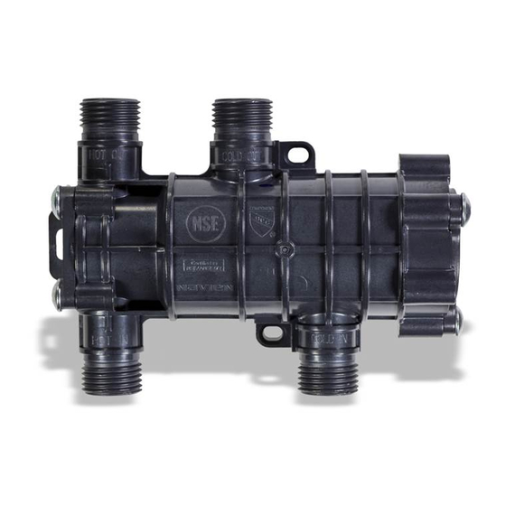
This device is designed
Note
and optimized for use with
Navien NPE-A/A2/S2 and
NPN Series water heaters
and NCB-H/NFC-H Series
combi boilers.
Advertisement
Table of Contents


Need help?
Do you have a question about the NaviCirc and is the answer not in the manual?
Questions and answers