
Related Manuals for Graytechnos photom 205A


Summary of Contents for Graytechnos photom 205A
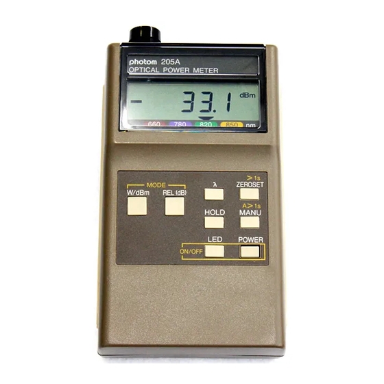
- Page 1 Optical Power Meter 光パワーメータ MODEL 205A/215 Instruction Manual 取扱説明書 HR1055-13J-10/20221205...
-
Page 3: Table Of Contents
INDEX 【 CAUTION 】 ................1 ............3 1. GENERAL INFORMATION ..............3 2. CONFIGURATION ..............4 3. SPECIFICATIONS 3 - 1. General ................. 4 3 - 2. Optical .................. 5 ..........5 4. OPERATING INSTRUCTIONS 4 - 1. Preparation ................5 4 - 2. -
Page 4: Caution
【 CAUTION 】 (1). The surface of the sensor built in the input port should be kept away from dust or other impurities, in particular, be careful removing and fitting connectors or adapters. When not in use, always cover the input/output port with blind caps. - Page 5 (8). Do not drop or swing the instrument with the strap. (9). When measuring in a bright place, do not allow ambient light to enter the sensor. (10). Do not input signals to the ANALOG jack. A recorder should be the one of high impedance (more than 100k). (11).
-
Page 6: General Information
1. GENERAL INFORMATION The hand-held 205A/215 Optical Power Meter is designed to measure optical power attenuation from fiber optic cables/devices used for optical communication. It is calibrated at four different wavelengths (205A: 660, 780, 820 and 850nm, 215: 850,1300,1310 and 1550nm) and directly reads the measurements at each wavelength. -
Page 7: Specifications
3. SPECIFICATIONS 3 - 1. General Measuring mode: Absolute value measurement (W, dBm) Relative value measurement (dB, REL) Measuring period: 3 times per second Display range: -70dBm to +10dBm(205A), -70dBm to +5dBm(215) Resolution: 0.1dB(205A), 0.01dB(215) or 1/3200 of display range Display: 3 1/2 digit LCD (max. -
Page 8: Optical
3 - 2. Optical MODEL 205A Sensor Si photodiode InGaAs photodiode Sensor φ8mm φ1mm Diameter 660, 780 850, 1300 Wavelength 820, 850nm 1310, 1550nm Measuring - 60dBm to +10dBm - 60dBm to +5dBm range (1nW to 10mW ) (1nW to 3.2mW ) ±3% ±3% Uncertainty... - Page 9 ① POWER Press the POWER key to operate the unit. Press the POWER key again, and the unit will be turned OFF. ② LED The light source unit (optional) is powered on and starts to emit. When LED is on, "LED" appears in the display. Press the LED key again, and the LED mode will be canceled.
- Page 10 ⑦ Analog output jack This jack is used to connect the unit to a recorder with the miniature plug. CAUTION: (1). Do not input signals to this jack. (2). A recorder should be the one of high impedance (more than 100k). ⑧...
-
Page 11: Function Keys
4 - 3. Function keys >1s ZEROSET MODE W/dBm REL(dB) A>1s HOLD MANU POWER ON /OFF Fig. 4 - 3 - 1 W/dBm The measured optical power is expressed in W or dBm. When the unit is turned on, it starts in the W mode automatically. - Page 12 (wavelength) This key is used to select the wavelength. The selected wavelength is indicated “▼” on the LCD. Whenever this key is pressed, the “ ▼ ” will move to other wavelength rotating through the four. By this operation, manual ranging will be canceled.
-
Page 13: Operation
AUTO MANU lowest range uppermost range Fig. 4 - 3 - 2 In order to return to the autoranging mode, press the W/dBm key or press and hold the MANU key for more than 1 second (A>1s). If the unit is turned off in the manual ranging mode, it will start in the same mode and the range selected when the unit was turned off at the next power on. - Page 14 (3). Measurement Fiber Remove the blind cap and tightly attach connector adapter Connector Blind cap appropriate to the fiber connector Connector used for measurement. adapter Input port To get accurate measurements, do not allow ambient light to enter the sensor and maintain the fiber in the same physical configuration during measurements as well as tighten the connectors securely.
-
Page 15: Light Source Unit And Battery Replacement
4 - 5. Light Source Unit and Battery Replacement (1). Light source unit replacement Pops out Turn unit before replacement. Slide the removal Light source unit catch upward so that the light Removal catch source unit pops out. When fitting the light source unit, align the key groove of the main unit and the light source unit, and insert the... -
Page 16: Cleaning Of The Sensor
4 - 6. Cleaning of the sensor Warning: The sensor surface of MODEL 215 is the glass of 0.3 mm in thickness. Do not clean the sensor directly with cleaning tools such as "Ferrule-mate", "One-Click-Cleaner" or "CLETOP-stick", with the connector adapter attached. -
Page 17: Optional Accessories
5. OPTIONAL ACCESSORIES In order to enable the instrument to provide additional measuring functions, the following optional products are available. Connector adapter / AC adapter Model No. Remarks Connector 180-FC adapter 180-SC 180-MU 180-ST Lucent 180-LC Lucent 180-SMA Anphenol SMA,906/905 180-HTL Toslink TOCP100, 150, 155, 200,... -
Page 18: Repair Service Information
6. REPAIR SERVICE INFORMATION When making requests for repair service, please bring the product to the distributor or send it directly to Graytechnos Head Office in Tokyo, Japan. When sending it, always pack it in its original or equivalent packing material and pack together with your name, address and telephone number. - Page 19 During the warranty period, we will, at our option, repair or replace any product, which proves to be defective. For warranty service, send the product prepaid to the distributor or Graytechnos Head Office in Tokyo, Japan. The repaired product will be returned prepaid to Buyer. Limitation of Warranty...
-
Page 20: 取扱上の注意
【 取扱上の注意 】 (1). 光センサ受光部はホコリ等によって性能が著しく悪化しますので、コネク タやアダプタ等の脱着時にホコリが入らない様に充分に注意して下さい。 使用しない時は必ず遮光キャップを取り付けて下さい。 (2). 使用前に「4-6 センサの清掃」にしたがってセンサ部を清掃してください。 (3). 光ファイバコネクタ以外のものをコネクタアダプタに挿入しないで下さい。 (4). 光ファイバコネクタは規格に準拠したものを使用して下さい。 規格に準拠しない光ファイバコネクタや裸心線ファイバアダプタを使用す る場合は、測定器に光ファイバパッチコードを接続して測定するか、コネ クタアダプタに光コネクタを接続したときにコネクタアダプタから突き出す フェルールの長さが 0.5mm 以下になるようにして下さい。規格に準拠し た光ファイバコネクタを接続した場合は 0.5mm 以下になります。 光ファイバコネクタ 光ファイバフェルール コネクタアダプタ コネクタアダプタから突き出す光ファイバフェルール ▼ の長さが 0.5mm 以下になること ▲ コネクタアダプタに光コネクタを接続したときの図 (5). 裸心線ファイバアダプタを使用する場合は、フェルール端面より石英ファ イバが突き出さないようにして下さい。 (6). 過大な光入力は光センサを破損しますので、測定範囲上限を著しく越え るような光を入光しないで下さい。 (7). 外部からの過大なノイズ等で正常に動作しなくなる事があります。その場 合は電源を入れ直して下さい。それでも回復しない場合は、一旦、電池を... - Page 21 (9). 明るい所で使用する時は、周囲光がセンサにもれこまないように十分注 意して下さい。 (10). アナログ出力端子に接続するレコーダ等は、入力インピーダンスの十分 高いもの(100KΩ以上)を使用して下さい。アナログ出力端子に外部か らの信号の印加は、行わないで下さい。 (11). 専用の AC アダプタ以外は絶対に使用しないで下さい、本器が破壊する 可能性があります。 -18-...
- Page 22 このたびは当社のオプトパワーメータをお買い上げいただきありがとうござい ます。本器は、すぐれた技術から創り出された信頼性の高い測定器です。はじ めに、この「取扱説明書」をよくお読みいただき、本器の操作に慣れてから、性 能を充分に発揮されるよう、御使用願います。 1. 概要 本器は、光ファイバを使用した光通信等の光パワー量、光減衰特性など を測定する、ハンディ型の光パワーメータです。 測定波長感度は、205A は 660, 780, 820, 850nm で、215 は 850, 1300, 1310, 1550nm で校正されており、その波長での測定値を直読可能 です。 先端のアダプタを交換することにより、各種のコネクタと接続可能です。 石英ファイバのみならず、プラスチックファイバにも対応できます。 光源ユニット(別売)を内蔵接続することにより、外部に光源を必要とす ることなく光損失を測定できます。 また、アナログ出力端子がついていますので、記録計に接続する事が 可能です。 2. 構成 本体とセンサ部、光源部(オプション)、そして各種の光ファイバに対応す るためのアダプタ部により構成されます。 各波長別光源ユニット 850nm, 660nm 1310nm, 1550nm 裸ファイバアダプタ プラスチックファイバ 本器 内蔵センサ...
-
Page 23: 3-1. 一般仕様
3. 規格 3-1. 一般仕様 品名 オプトパワーメータ 測定機能 絶対値測定 W , dBm、 相対値測定 dB (REL) 表示周期 3 回/秒 表示範囲 +10dBm ~ -70dBm(205A)、 +5dBm ~ -70dBm(215) 分解能 W 表示時:0.1%、0.1dB(205A)、 0.01dB(215) レンジ切替 自動又は手動:7 レンジ(205A)、 6 レンジ(215) レンジ間誤差 1%以内 表示 表示器:LCD、有効表示桁数 :3・1/2 桁、3200 カウント オーバーフロー表示... -
Page 24: 3-2. オプトメータ仕様
3-2. オプトメータ仕様 型名 205A 受光素子 Si フォトダイオード InGaAs フォトダイオード 受光径 φ8mm φ1mm 校正波長 660, 780, 820, 850nm 850, 1300, 1310, 1550nm - 60dBm ~ + 10.0dBm - 60dBm ~ + 5.0dBm 測定範囲 (1nW~10mW ) (1nW~3.2mW ) 測定値の ±3% ±3% 不確かさ (850nm, -20dBm オフセッ... - Page 25 ④.受光部(INPUT 側) 光パワーを入力する接続部でセンサが内蔵されています。コネクタアダ プタを取り付け、コネクタ付の光ファイバを接続して測定します。コネクタ アダプタを交換することにより、各種のコネクタと接続可能です。 汚れにより性能、精度が著しく低下します。使用の前に清掃をしてくださ い。(「4-6 センサの清掃」参照)。 ⑤.光源出力部(OUTPUT 側) 光源出力部です。コネクタアダプタを取り付け、光ファイバを接続して使 用します。コネクタアダプタを交換することにより、各種のコネクタを接続 可能です ⑥.表示器 3・1/2 桁の LCD 表示器で、測定データの他に多種のモード、単位、ステ ータス等の表示があります。 表 示 文 字 LED, -(符号), BT(電池低下) , ▼(波長指示), dBm, nW, μW , mW MANU, HOLD, REL, dB, ⑦.アナログ出力端子 レコーダ等に接続するための出力端子です。小形単頭プラグを接続しま す。 注意:...
-
Page 26: 4-3. 操作スイッチ
⑩.フックナット M3 ナットです。ストラップを固定するなど、御自由にお使い下さい。 4-3. 操作スイッチ >1s ZEROSET MODE REL(dB) W/dB A>1s HOLD MANU POWER ON /OFF 図 4-3-1 操作スイッチ配置図 モード切替 W / dBm 受光コネクタから入力した光のパワーを W(ワット)又は dBm(ディービ ーエム)で表示します。最初の電源立ち上げ時は、W モードで以下このボ タンを押すごとに、W,dBm 交互にモードが切り換わります。電源を切っ て次に電源を立ち上げる時は、電源を切る前に設定されていたモードに なります。 W モードでは、入力パワーにより nW(ナノワット=10 W),μW(マイク ロワット=10 W),mW(ミリワット=10 W)の単位で表示されます。また、 W モードにおいてのみ、... - Page 27 ません。REL モードはオートレンジ専用です。又、モード表示として、相対 値表示の時”REL”が点灯します。 λ (ラムダ) λボタンは波長感度設定用のボタンで、LCD 上の▼印が示す波長で 測定値が校正されます。 このボタンを押すごとに波長感度が切り換わります。この操作によりマ ニュアルレンジは解除されます。 設定された波長は、次の電源立ち上げ時に自動的に選択されます。 ZEROSET >1s これは受光部分のオフセットを自動調整するボタンで、特に微弱光を測 定する場合、大きな誤差となる受光部のオフセット電圧をキャンセルする ためのものです。 自動調整をスタートするためには、受光コネクタを完全に遮光し、この ボタンを1秒以上押し続けて下さい (>1s) 。LCD 上には、自動調整中を 示す表示がされ、約20秒で完了します。ただし、W、dBm モードのみで 動作し、REL モード又は HOLD では自動調整を行いません。 また、完全に遮光せずに自動調整をして適切な調整が行われなかった 時は、”Err” が表示されます。”Err” になった時又は自動調整を中止させ たい時は、再度このボタンを押して下さい。この時、オフセットは操作を行 う以前の状態に戻ります。 HOLD 測定されたデータをホールドするボタンです。ホールド中は ”HOLD” が表示され、このボタン及びモード切り替えボタン(W / dBm,REL)以外 は無視されます。W / dBm ボタンにより、ホールドデータの W / dBm 変 換が行えます。...
-
Page 28: 4-4. 使用法
後レンジアップします。最上位レンジでボタンを押すと最下位レンジに移 行します。 マニュアルからオートに戻す時は、W / dBm ボタンを押すか、又は MANU ボタンを1秒以上押し続けて下さい (A>1s) 。 マニュアルレンジで電源を切った場合、次の電源立ち上げ時は自動的 にマニュアルの同じレンジになります。 AUTO 現行レンジへ移行 最下位レンジ 最上位レンジ 図 4-3-2 [W / dBm] + [REL] + [電源 ON] W / dBm と REL を同時に押しながら電源スイッチを ON することにより 全ての設定値及び動作モードを初期状態に復帰します。 初期状態とは、この製品が出荷時に設定されている動作状態です。つ まり、W 表示、オートレンジ、波長 850nm(205A)または 1550nm(215)の 状態です。... - Page 29 (3). 測定 遮光キャップをはずし、使用す 光ファイバ るファイバに適合するコネクタア ダプタをしっかりと取り付けます。 コネクタ 光パワーの測定は、ファイバの 遮光キャップ 状態やコネクタの種類により測定 コネクタアダプタ 値に影響します。特に微弱パワ 受光部 ー域での測定では、周囲光がセ ンサにもれこまないようにし、ファ イバの状態を同一に保ち、コネク タは確実に締め付けて下さい。又、 センサの受光面には、ゴミ等が 図 4-4-1 付着しないよう常に注意し、使用 の前に清掃をしてください。「4-6 センサの清掃」参照。 光パワー測定中本器の測定範囲外のパワーを入力した場合は、次の 様なオーバー/アンダー表示となります。 マニュアルレンジ 3200 カウント以上の時 ”Hi “、及び W モード 10.00mW(205A), 3.2mW(215)以上の時 “Hi” +10.0dBm(205A), +5.0dBm(215)以上の時 “Hi “、 dBm 及び 及び-70dBm 以下の時...
-
Page 30: 4-5. 光源および電池等の交換方法
飛び出す 4-5. 光源および電池等の交換方法 光源部 (1). 光源の交換 脱着ノブ 光源を交換する場合は、必ず電源を 切り、本体裏面の脱着ノブを上側にスラ イドさせると光源部は飛び出します。取り 付ける時は、光源部と本体部の凹凸を併 本体裏面部 押す せて”カチッ”と音がして止まるまで挿入 して下さい。 図 4-5-1 (2). 電池交換 使用中に BT マークが点灯した場合 電池 本体裏面部 は速やかに新しい電池と交換して下さい。 単三 4 本 電池は 4 本同時に交換し、古い電池との 併用は避けて下さい。 電池蓋 図 4-5-2 -27-... -
Page 31: 4-6. センサの清掃
4-6. センサの清掃 警告: のセンサ表面は厚さ のガラスで MODEL215 0.3mm す。コネクタアダプタをつけたまま、「フェルールメイト」、「ワン クリッククリーナー」等の清掃用具や「クレトップ綿棒」等で直 接センサを清掃しないでください。また、綿棒で力を入れてセ ンサ面を擦らないでください。センサ面が割れたり傷ついたり することがあります。 注意: センサ部を清掃する場合は必ずコネクタアダプタをは ずしてから清掃して下さい。 使用の前後に、センサ部からコネクタアダプタや保護キャップをはずし て、センサ面に汚れや塵が付いてないことを拡大鏡等で目視確認してく ださい。汚れや塵が付いていたら、きれいなエアーブローで吹き飛ばして ください。 センサ面の汚れがエアーだけでは取れない場合、綿棒でセンサのガラ ス面のよごれを優しくこすり取ってください。綿棒は未使用の乾いたもの を使用します。拡大鏡で確認し、汚れが取れていたら完了です。一度使っ た綿棒は再使用せずに捨ててください。 MODEL215 の場合、センサに汚れがこびりついている時は以下の方 法で清掃してください。 ①無水エタノール等をセンサ面に数滴たらし、綿棒でセンサ面の 汚れを優しくこすり取ってください。 ②その後、直ちに新しい乾いた綿棒でセンサ面のエタノール等を 拭い取ってください。 センサ面を拡大鏡等で観察し、汚れが残っている場合は①②を繰り返 してください。一度使った綿棒は再使用せずに捨ててください。 警告: では、センサの清掃にエタノール等の MODEL205A 有機溶剤を決して使用しないで下さい。 -28-... -
Page 32: オプション
5. オプション 本器には数多くの測定機能がありますが、その性能を充分に発揮させるた め、次の様なオプション製品が用意されています。 品名 型名 備考 FC 型 180-FC SC 型 180-SC MU 型 180-MU ルーセント ST 型 180-ST コ ルーセント LC 型 180-LC 石 ネ SMA,906/905 型 英 180-SMA ANPHENOL ク フ タ トスリンク等 180-HTL TOCP100, 150, 155, 200, 255 ァ... -
Page 33: アフターサービス
6. アフターサービス 御使用中に万一故障した場合は、保証書の規定内容に従って修理いたしま す。その場合は、お手数でもお買い上げの代理店又は弊社に返送して下さい。 返却の場合は充分クッション材等で保護してからダンボール等の外箱に収納 して、故障内容、住所、氏名、電話番号を明記し、保証書のコピーを同梱して 下さい。 仕様、デザイン等は予告なく変更することがあります。 グレイテクノス株式会社 〒110-0005 東京都台東区上野 1-9-2 ビルボビル 2F 電話:03-5807-6081 Fax:03-5807-6082 www.graytechnos.com email: customer@graytechnos.com -30-... - Page 34 - メ モ -...
- Page 35 - メ モ -...
- Page 36 保証書 グレイテクノス株式会社 保 証 規 定 1. 保証期間中に正常な使用状態で、万一故障等が生じました場合は無償 で修理いたします。 2. 本保証書は、日本国内でのみ有効です。 3. 下記事項に該当する場合は、無償修理の対象から除外いたします。 a. 不適当な取扱い使用による故障 b. 設計仕様条件等をこえた取扱い、または保管による故障 c. 当社もしくは当社が依嘱した者以外の改造または修理に起因する故障 d. その他当社の責任とみなされない故障 シリアル No. 機 種 名 保証期間 年 月 日 1 ヶ年 お名前. 様 ご住所. お 客 様 電話番号. 販 売...
Need help?
Do you have a question about the photom 205A and is the answer not in the manual?
Questions and answers