Advertisement
Quick Links
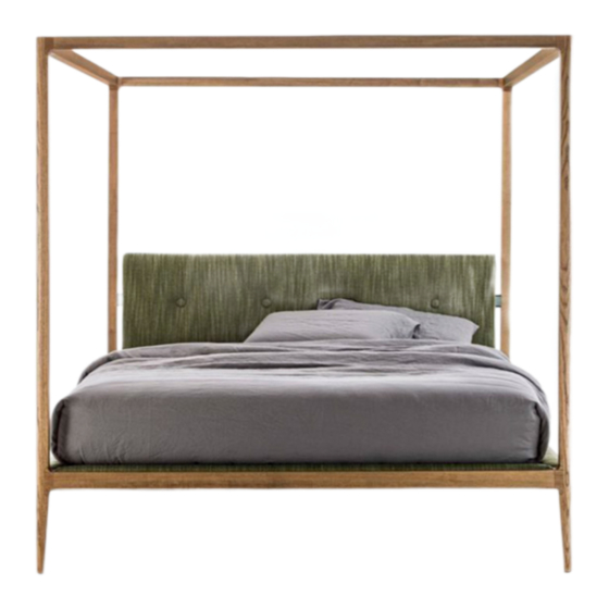
ZIGGY BED BALDACCHINO
Design: C. Ballabio
Istruzioni di montaggio
Assembly instruction
(MIN. 2x)
A
G
C
Nell'imballaggio troverete la struttura del letto scomposta in 6 parti (A-B-C-D-E-F), la rete e gli elementi di fissaggio (viti, bulloni e
piastre G-H).
In the package you will find the bed base disassembled into 6 pieces (A-B-C-D-E-F), the slatted bed base and the fixing elements
(screws, bolts and supports G-H).
F
G
H
H
G
E
H
G
H
D
B
Advertisement

Related Manuals for porada ZIGGY BED BALDACCHINO


Summary of Contents for porada ZIGGY BED BALDACCHINO
- Page 1 ZIGGY BED BALDACCHINO Design: C. Ballabio Istruzioni di montaggio Assembly instruction (MIN. 2x) Nell’imballaggio troverete la struttura del letto scomposta in 6 parti (A-B-C-D-E-F), la rete e gli elementi di fissaggio (viti, bulloni e piastre G-H). In the package you will find the bed base disassembled into 6 pieces (A-B-C-D-E-F), the slatted bed base and the fixing elements...
- Page 2 Avvitare i 2 perni in metallo nei 2 fori corrispondenti all’estremità della parte A (come indicato nel disegno), in modo che il foro del perno sia orientato vericalmente. Inserire le 2 spine in legno nei corrispondenti fori (come indicato nel disegno) all’estremità della parte A, aiutandosi con un martello.
- Page 3 ATTENZIONE: LE TACCHE DELLE BUSSOLE DEVONO ESSERE ORIENTATE NELLA DIREZIONE DEL FORO ATTENTION: THE CUTS ON THE SOCKETS MUST BE ORIENTED TOWARDS THE CORRESPONDING HOLES ATTENZIONE: ALLENTARE LE VITI AL MASSIMO ATTENTION: UNFASTEN THE SCREWS TO THEIR MAXIMUM EXTENSION Infilare le 8 bussole alle estremità delle parti C e D, facendo attenzione che il foro sia orientato correttamente (come mostrato in figura) ed appoggi sul fondo.
- Page 4 CRACK Fissare l’elemento C all’elemento A, facendo attenzione a non lasciare il componente C a sbalzo, senza supporto o appoggio a terra. Fix part C to the part A, paying attention not to leave the component C cantilever, without support or without laying on the ground.
- Page 5 CRACK Serrare le 2 viti con l’apposita chiave a brugola, come mostrato in figura (solo sul lato della testata A). Fasten the 2 screws with the allen key, as shown above in the drawing (headboard A side only).
- Page 6 Avvitare i 2 perni in metallo nei 2 fori corrispondenti all’estremità della parte B (come indicato nel disegno), in modo che il foro del perno sia rivolto verso l’alto. Inserire le 2 spine in legno nei corrispondenti fori (come indicato nel disegno) all’estremità della parte B, aiutandosi con un martello.
- Page 7 ATTENZIONE: NON SERRARE COMPLETAMENTE LE VITI INFERIORI ATTENTION: DO NOT FASTEN THE LOWER SCREWS COMPLETELY Fissare l’elemento B all’elemento C, senza serrare completamente le viti inferiori. Fix part B to part C, without fastening the lower screws completely.
- Page 8 Avvitare i 4 perni in metallo nei 4 fori corrispondenti alle estremità superiori delle parti A e B(come indicato nel disegno), in modo che il foro del perno sia rivolto verso l’alto. Screw the 4 metal pins into the corresponding holes on the upper sides of parts A and B so that the pin hole is facing up.
- Page 9 ATTENZIONE: LE TACCHE DELLE BUSSOLE DEVONO ESSERE ORIENTATE NELLA DIREZIONE DEL FORO ATTENTION: THE CUTS ON THE SOCKETS MUST BE ORIENTED TOWARDS THE CORRESPONDING HOLES ATTENZIONE: ALLENTARE LE VITI AL MASSIMO ATTENTION: UNFASTEN THE SCREWS TO THEIR MAXIMUM EXTENSION Infilare le 4 bussole alle estremità delle parti C e D, facendo attenzione che il foro sia orientato correttamente (come mostrato in figura) ed appoggi sul fondo.
- Page 10 Fissare l’elemento F alla struttura A, inclinando leggermente il lato della pediera (B) verso l’esterno. Fix part F to part A, slightly tilting the footboard side (B) outwards.
- Page 11 ATTENZIONE: NON SERRARE COMPLETAMENTE ATTENTION: DO NOT FASTEN COMPLETELY Serrare soltanto la vite sul lato testata (A) con l’apposita chiave a brugola, come mostrato in figura. Fasten only the screw on the headboard side (A) with the allen key, as shown above in the drawing.
- Page 12 Inserire e fissare l’elemento D alla struttura A, allontanando leggermente il lato della pediera (B) verso l’esterno. Insert and fix part D to part A, slightly moving the footboard side (B) outwards.
- Page 13 ATTENZIONE: NON SERRARE COMPLETAMENTE ATTENTION: DO NOT FASTEN COMPLETELY Serrare soltanto le 2 viti sul lato testata (A) con l’apposita chiave a brugola, come mostrato in figura. Fasten only the 2 screws on the headboard side (A) with the allen key, as shown above in the drawing.
- Page 14 Fissare l’elemento E alla struttura A, allontanando leggermente il lato della pediera (B) verso l’esterno. Fix part E to part A, slightly moving the footboard side (B) outwards.
- Page 15 ATTENZIONE: NON SERRARE COMPLETAMENTE ATTENTION: DO NOT FASTEN COMPLETELY Serrare soltanto la vite sul lato testata (A) con l’apposita chiave a brugola, come mostrato in figura. Fasten only the screw on the headboard side (A) with the allen key, as shown above in the drawing.
- Page 16 Serrare le 4 viti dei traversi inferiori C e D con l’apposita chiave a brugola, come mostrato in figura. Fasten the 4 screws on the lower sides C and D with the allen key, as shown above in the drawing.
- Page 17 Serrare le 2 viti sui traversi superiori E ed F con l’apposita chiave a brugola, come mostrato in figura. Fasten the 2 screws on the upper sides E and F with the allen key, as shown above in the drawing.
- Page 18 Avvitare i supporti nelle rispettive sedi con le apposite viti svasate. Screw the supports in the correponding position with the countersunk screws provided.
- Page 19 Avvitare manualmente il piedino di sostegno in rotazione nell’apposito foro centrale della rete. Appoggiare la rete ai supporti precedentemente montati. Manually screw and fix the supporting central foot to the slatted bed base. Place the slatted bed base on the supports previously assembled.
- Page 20 PORADA Arredi s.r.l. - 22060 Cabiate (Como) - Italia - via B. Buozzi, 2 - Tel. +39 031 766215 - Fax +39 031 768386 - info@porada.it - www.porada.it...
Need help?
Do you have a question about the ZIGGY BED BALDACCHINO and is the answer not in the manual?
Questions and answers